EP4306760A1 - Porte tournante et procédé de construction d'une porte tournante - Google Patents
Porte tournante et procédé de construction d'une porte tournante Download PDFInfo
- Publication number
- EP4306760A1 EP4306760A1 EP22184163.8A EP22184163A EP4306760A1 EP 4306760 A1 EP4306760 A1 EP 4306760A1 EP 22184163 A EP22184163 A EP 22184163A EP 4306760 A1 EP4306760 A1 EP 4306760A1
- Authority
- EP
- European Patent Office
- Prior art keywords
- cover plate
- elements
- filler
- revolving door
- ceiling assembly
- Prior art date
- Legal status (The legal status is an assumption and is not a legal conclusion. Google has not performed a legal analysis and makes no representation as to the accuracy of the status listed.)
- Pending
Links
- 238000000034 method Methods 0.000 title claims description 19
- 239000000945 filler Substances 0.000 claims abstract description 59
- 239000011521 glass Substances 0.000 claims description 15
- 239000000463 material Substances 0.000 claims description 10
- 239000002131 composite material Substances 0.000 claims description 6
- 238000004519 manufacturing process Methods 0.000 claims description 5
- 239000004033 plastic Substances 0.000 claims description 5
- 229920003023 plastic Polymers 0.000 claims description 5
- 238000010438 heat treatment Methods 0.000 claims description 4
- 229910000831 Steel Inorganic materials 0.000 claims description 2
- 229910052782 aluminium Inorganic materials 0.000 claims description 2
- XAGFODPZIPBFFR-UHFFFAOYSA-N aluminium Chemical compound [Al] XAGFODPZIPBFFR-UHFFFAOYSA-N 0.000 claims description 2
- 229920002635 polyurethane Polymers 0.000 claims description 2
- 239000004814 polyurethane Substances 0.000 claims description 2
- 239000010959 steel Substances 0.000 claims description 2
- 238000009423 ventilation Methods 0.000 claims description 2
- 238000010276 construction Methods 0.000 description 4
- 238000005187 foaming Methods 0.000 description 4
- 238000009434 installation Methods 0.000 description 4
- 230000000903 blocking effect Effects 0.000 description 3
- 238000003825 pressing Methods 0.000 description 3
- 238000013461 design Methods 0.000 description 2
- 229920000877 Melamine resin Polymers 0.000 description 1
- 229920005830 Polyurethane Foam Polymers 0.000 description 1
- 239000000853 adhesive Substances 0.000 description 1
- 230000001070 adhesive effect Effects 0.000 description 1
- 239000001913 cellulose Substances 0.000 description 1
- 229920002678 cellulose Polymers 0.000 description 1
- 238000010924 continuous production Methods 0.000 description 1
- 239000011162 core material Substances 0.000 description 1
- 230000001419 dependent effect Effects 0.000 description 1
- 238000011161 development Methods 0.000 description 1
- 230000018109 developmental process Effects 0.000 description 1
- 239000006260 foam Substances 0.000 description 1
- 238000003780 insertion Methods 0.000 description 1
- 230000037431 insertion Effects 0.000 description 1
- 230000010354 integration Effects 0.000 description 1
- JDSHMPZPIAZGSV-UHFFFAOYSA-N melamine Chemical compound NC1=NC(N)=NC(N)=N1 JDSHMPZPIAZGSV-UHFFFAOYSA-N 0.000 description 1
- 229910052751 metal Inorganic materials 0.000 description 1
- 239000002184 metal Substances 0.000 description 1
- 238000003801 milling Methods 0.000 description 1
- 239000011490 mineral wool Substances 0.000 description 1
- 238000012544 monitoring process Methods 0.000 description 1
- 230000002093 peripheral effect Effects 0.000 description 1
- 230000000284 resting effect Effects 0.000 description 1
Images


Classifications
-
- E—FIXED CONSTRUCTIONS
- E06—DOORS, WINDOWS, SHUTTERS, OR ROLLER BLINDS IN GENERAL; LADDERS
- E06B—FIXED OR MOVABLE CLOSURES FOR OPENINGS IN BUILDINGS, VEHICLES, FENCES OR LIKE ENCLOSURES IN GENERAL, e.g. DOORS, WINDOWS, BLINDS, GATES
- E06B3/00—Window sashes, door leaves, or like elements for closing wall or like openings; Layout of fixed or moving closures, e.g. windows in wall or like openings; Features of rigidly-mounted outer frames relating to the mounting of wing frames
- E06B3/90—Revolving doors; Cages or housings therefor
Definitions
- the invention relates to a revolving door with a turnstile, which is arranged between opposing drum elements, and with a ceiling assembly, which is arranged on the top of the drum elements and on which the turnstile is rotatably mounted.
- the invention further relates to a method for producing a ceiling assembly for a revolving door.
- a revolving door is known with a turnstile which is arranged between opposing drum elements and with a ceiling assembly which is arranged on the top of the drum elements and on which the turnstile is rotatably mounted.
- the revolving door thus has two opposing drum elements with a turnstile arranged between them, and the ceiling assembly is located on top of the turnstile and goes into the structurally and structurally in the Drum elements above.
- the ceiling assembly forms a load-bearing structure with the drum elements, and the ceiling assembly has a connecting element arranged in the center of the revolving door and beams extending radially therefrom are provided, within the drum walls and below the ceiling assembly the turnstile is arranged suspended from the ceiling assembly, with the beams extending from the center to the drum walls held under tension to produce an upward force on the connecting element.
- the complex structure of the ceiling assembly in conjunction with the drum elements makes it clear that the revolving door with the individual parts of the ceiling assembly can only be assembled on site, in particular by integrating it into a wall or into a glass facade of a building.
- the assembly of such a revolving door is complex and the individual components of the ceiling assembly must be adapted to the dimensions on site, so that the effort required to assemble the revolving door is also significantly increased.
- Another embodiment of a revolving door is from the EP 3 611 326 B1 known. It can also be seen here that the structure of the ceiling assembly is complex and must be assembled on site in a structural unit with the drum elements. In particular, the ceiling assembly has a large number of individual parts that have to be connected to the drum elements in a complex manner.
- the object of the invention is to simplify the construction of a revolving door, especially in connection with the ceiling assembly should be provided in the simplest possible way and arranged on the top side of the elements, and on which the turnstile is finally rotatably mounted.
- An improved ceiling assembly is intended to significantly simplify the on-site assembly of the revolving door and reduce the time required for this.
- the ceiling assembly has a sandwich structure with at least one bottom cover plate and/or at least one top cover plate and at least one filler.
- the basic idea of the invention is to create a modular ceiling assembly that has a sandwich structure, so that at least one filler is provided as a core material, and the filler has a cover plate on at least one cover surface or on both cover surfaces.
- only one top cover plate, only one bottom cover plate or one top and one bottom cover plate can be provided, which preferably run parallel to one another and between which the filler is located.
- An intermediate level may be necessary, for example, to increase the rigidity of the ceiling assembly and to accommodate components within the ceiling assembly or to hold them together or to reinforce each other in their overall structure.
- the basic idea provides for a sandwich structure that enables a modular ceiling assembly that can be handled in a modular manner, which can be connected as a whole to the drum elements on site, in particular can be placed on the top of the drum elements, preferably with the turnstile rotatably received between the drum elements.
- the terms bottom and top refer to the installed condition of the revolving door.
- drum elements can have the structure described in connection with the ceiling assembly.
- the modular ceiling assembly preferably results in an individually manageable assembly that can be attached to the drum elements and/or the turnstile and can be detached from the drum elements and/or the turnstile, in particular reversibly.
- the ceiling assembly can be pre-assembled at the factory in such a way that the ceiling assembly only needs to be connected to the drum elements and the turnstile at the destination, without the ceiling assembly having to be assembled or assembled in its basic components on site. This results in significantly shorter assembly times and the general structure of the ceiling assembly is simplified.
- the ceiling assembly is designed as a module that can be attached to the other components of the revolving door, which is arranged on the drum walls and the turnstile and can also be removed from the position of the arrangement.
- the basic structure of the ceiling assembly provides that at least partially on or over or above the bottom cover plate and / or on or above or above the top cover plate, in particular in the area of the filler, one or more structural elements and / or functional elements of the revolving door are accommodated.
- structural elements and/or functional elements can also protrude laterally, in particular radially, or from the top or bottom of the cover plates.
- the structural elements and/or functional elements can be surrounded by the filler or they are embedded in the filler.
- a plate motor for rotatably driving the turnstile can be arranged on the underside of the ceiling assembly in such a way that it is, for example, partially integrated within the ceiling assembly and partially protrudes from it.
- Such motors are also known as torque or disc motors and are usually connected to the turnstile without gears.
- the structural elements can, for example, migrate diametrically through the ceiling assembly and/or the structural elements can connect the top and bottom cover plates to one another or be connected to only one cover plate.
- the filler is introduced between the cover panels in such a way that it surrounds the structural elements and/or the functional elements, the structural elements and/or the functional elements can also divide the filler into several sub-elements if, for example, the elements completely traverse the ceiling assembly.
- a truss-like structure is conceivable star-shaped structure or, for example, a rectangular or hexagonal structure to stiffen the ceiling assembly accordingly.
- the bottom cover plate and/or the top cover plate has one or more openings, so that one or more structural elements and/or functional elements can be arranged in connection with the openings.
- the one or more openings can be designed as boreholes.
- the one or more functional elements include a drive, a controller, a sensor device, a lighting device, a loudspeaker device, a power supply, a lock, a ventilation device, a heating element and / or the like, in particular wherein the functional elements have openings or in one or more recesses can be introduced into other recesses or intermediate areas in the filler.
- a heating element can reduce any possible snow load on the revolving door.
- the bottom cover plate and/or the top cover plate are connected to the filler materially and/or non-positively and/or positively.
- the at least one cover plate is glued, soldered and/or welded to the filler and/or optionally also to the structural elements and/or functional elements, with non-positive or positive connections also being possible, for example by pressing the cover plate into corresponding ones Counter elements, in particular in or on the filler, on the structural elements and/or on the functional elements.
- the bottom cover plate and/or the top cover plate can be connected to one another with the filler in a thermal composite process. It is therefore possible that after the ceiling assembly has been assembled with the filler and the cover panels and optionally also with other functional and structural elements, the sandwich thus formed is thermally pressed in an oven, i.e. literally baked, by applying a pressing force and heating the cohesive layer Composite is created, whereby in particular the parallelism of the cover panels and the exact height of the ceiling assembly can be calibrated at the same time.
- the bottom cover plate and/or the top cover plate can be made of an aluminum material, a steel material and/or a plastic material, in particular a fiber-reinforced, preferably glass fiber-reinforced, plastic and/or a glass material and/or the filler can be a polyurethane material and / or have a honeycomb structure.
- the filler can alternatively also consist of cellulose, mineral wool and/or melamine, with a foamed filler also being possible; in particular, the filler can be foamed in between the cover plates and the functional elements and/or structural elements using the foaming process, for example based on a PU foam .
- a holding device can be set up with which the components of the ceiling assembly are held in one position, and then the filler is introduced in the foaming process.
- cover plates in a parallel belt system and to foam in the filler, so that at least the structure from the filler and the at least one preferably two cover plates can be produced in a continuous process, and then structural and / or functional elements and other features , such as openings, can be set up in at least one of the cover plates and the like by, for example, milling outs being provided in the raw sandwich body in order to introduce the structural and/or functional elements.
- the structural elements can penetrate the filler and/or it is provided that the filler is divided into at least two or more parts by the structural elements. Particularly when intermediate cover panels are set up, the filler can also be divided into an upper filling level and a lower filling level.
- the ceiling assembly is arranged on the drum elements in such a way that they laterally enclose the ceiling assembly and/or that the drum elements extend to the height of the top cover plate and/or that the drum elements are in particular flush with the top cover plate. It is also possible for the drum elements to extend at least over part of the height of the ceiling assembly, with particular advantage being the connection between the drum elements and the ceiling assembly based on a cohesive connection, in particular an adhesive connection.
- a ceiling device is preferably arranged to rotate at the turnstile.
- the ceiling device covers the underside of the ceiling assembly and/or the ceiling device has a diameter that essentially corresponds to the diameter of the ceiling assembly.
- Such a rotating ceiling device further improves the modular design of the individual assembly elements.
- the ceiling device can hide the potentially unsightly ceiling assembly and thus make walking on it more comfortable for the visitor.
- the turnstile can comprise wing elements, wherein the ceiling device can have sections which are arranged between the wing elements at the upper end of the turnstile pointing towards the ceiling device.
- the sections can be connected to or on the wing elements in a non-positive and/or cohesive and/or form-fitting manner, and it can be provided that the sections form a stiffening structure for the wing elements and therefore also for the turnstile as a whole.
- the number of sections can match the number of wing elements of the turnstile. It is therefore possible that the sections, when arranged on the wing elements, form a structure that aligns the wing elements with one another and/or forms a stiffening structure.
- the ceiling device it is particularly advantageous for the ceiling device to have at least one light source. It is also conceivable that the ceiling device has a sensor means, a monitoring means, a blocking means for blocking the rotational movement of the turnstile or, for example, a loudspeaker or scenting device.
- the drum elements each have an inner glass element and an outer glass element, with the ceiling assembly resting directly or indirectly on an upper end surface of the inner glass element and/or on an upper end surface of the outer glass element.
- glass can be designed in different ways, in particular as plastic glass or the like.
- the inner glass element can have a shorter vertical length than the outer glass element, so that the outer glass element encloses the ceiling assembly on the outside at least partially or completely, in particular with regard to the height and / or with respect to the circumference of the ceiling assembly, when the ceiling assembly is on the upper end surface of the inner glass element and/or rests on the upper end surface of the outer glass element.
- the ceiling assembly can be connected, in particular glued, to the drum elements or preferably rest on a profile element, which in turn can be connected, in particular glued, to the drum elements.
- the invention relates to a method for producing a ceiling assembly for a revolving door, in particular which is designed as described above, the method comprising at least the following steps, in particular in the order listed: providing a bottom cover plate and / or providing a top cover plate; in particular setting up the structural elements and/or functional elements on or on the bottom cover plate and/or on or on the top cover plate; Introducing a filler to the bottom cover plate and/or to the top cover plate and connecting, in particular cohesively and/or non-positively and/or positively, the bottom cover plate and/or the top cover plate with the filler.
- the top cover plate can also initially be set up on the underside in order to set up the filler and/or the structural and/or functional elements.
- the ceiling assembly has only one bottom cover plate, only one top cover plate or one bottom and one top cover plate, since the top and bottom of the cover plates are only defined in the final installation situation and the ceiling assembly, for example can also be expanded later lying on the top side.
- the filler can be arranged in various ways on the at least one or between both cover plates.
- the filler can be arranged in the geometrically prefabricated elements in the intermediate regions between the structural elements and/or functional elements. It is also conceivable that the filler is foamed and thus fills the spaces between the cover plates and/or the structural elements and functional elements and stiffens the structural and/or functional elements with one another or even holds them in position exclusively through the filler itself.
- the cohesive connection of the bottom cover plate and/or the top cover plate with the filler can be produced using a thermal composite process, in particular by introducing heat and applying a corresponding pressing force.
- the arrangement of a jacket body such as a circumferential sheet metal or a plastic band on the circumference is possible in order to close the filler in the radial direction to the outside.
- the method provides in particular that the ceiling assembly is designed as an individually manageable assembly, which is attached to the drum elements and/or the turnstile in a particularly reversibly detachable manner. It is particularly advantageous for the ceiling assembly to be detached from the drum elements at any time.
- the ceiling assembly is essentially completely pre-assembled at the factory and is brought to the destination of the revolving door as a finished assembly. This results in a significantly reduced installation effort at the installation site of the revolving door.
- Figure 1 shows a perspective view of a revolving door 100 with a turnstile 10, which is arranged between opposing drum elements 11, and with a ceiling assembly, which is arranged on the top of the drum elements 11, and on which the turnstile 10 is rotatably mounted.
- the ceiling assembly 12 has a sandwich structure that is similar in terms of its structure and manufacturing steps to the following Figures 2, 3 and 4 is explained in more detail.
- Figure 2 shows an example of an underside cover plate 13, which forms a circular disk and therefore has a diameter that corresponds approximately to the diameter of the revolving door 100 or at least to the diameter on the inside of the drum elements.
- Several openings 18 are made in the underside cover plate 13, into which functional elements such as loudspeakers, lighting devices, sensors, scenting devices and the like can later be inserted.
- Figure 3 shows the underside cover plate 13 with the openings 18 and structural elements 16 applied to the cover plate 13, which are designed, for example, in a truss-like manner and are located between the openings 18.
- Figure 4 shows the structure of the underside cover plate 13 with the openings 18 and the structural elements 16, whereby functional elements 17 are also set up, between which parts of the filler 14 are finally inserted.
- the functional elements 17 relate, for example, to a drive 19 for rotating the turnstile, a control 20, a sensor device 21, a lighting device 22 or a loudspeaker device 23.
- the exemplary embodiment shows individual parts of the filler 14, the filler 14 being shown as dimensionally stable parts, which can alternatively also be foamed between the structural elements 16 and the functional elements 17.
- the ceiling assembly 12 is shown in a cross section, and the essential components are formed by the bottom cover plate 13, the top cover plate 15 and the filler 14 arranged between the cover plates 13 and 15.
- the structural elements 16 shown as examples migrate through the filler 14 in such a way that it is divided into several components, which can also be related in some areas. Particularly when the filler is introduced between the cover plates 13, 15 in the foaming process, it is advantageous if the structural elements 16 do not completely separate the filler 14 into separate parts, but rather there are connections between skin structures of the filler.
- the horizontally extending structural element 16 can also form a further intermediate cover plate.
- the functional elements 17 are shown by way of example as a drive to which the turnstile can be attached in a manner not shown in detail, a controller 20, a sensor device 21, a lighting device 22 and a loudspeaker device 23.
- brake devices and / or blocking devices for braking and to block the rotation of the turnstile.
- Figure 6 shows again the components of the revolving door 100, including the turnstile, the drum walls 11 and the ceiling assembly 12.
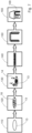
- Figure 7 shows schematically a sequence of the method for producing the ceiling assembly for a revolving door 100, the method having at least the following steps: First, the underside cover plate 13 is provided in a provision step 110. Subsequently, in a setup step 120, the underside cover plate is provided with structural elements 16 and/or functional elements 17, followed by an introduction step 130, according to which the filler is set up. The sandwich structure of the ceiling element is then essentially completed with an arrangement step 140 for arranging the top cover plate, whereupon in a completion step 150 the ceiling assembly is brought to the destination in accordance with the arrangement step 140. In the following construction step 160, the components of the revolving door 100 are assembled.
Landscapes
- Engineering & Computer Science (AREA)
- Civil Engineering (AREA)
- Structural Engineering (AREA)
- Extensible Doors And Revolving Doors (AREA)
Priority Applications (4)
| Application Number | Priority Date | Filing Date | Title |
|---|---|---|---|
| EP22184163.8A EP4306760A1 (fr) | 2022-07-11 | 2022-07-11 | Porte tournante et procédé de construction d'une porte tournante |
| US18/345,457 US20240011349A1 (en) | 2022-07-11 | 2023-06-30 | Revolving door and method for assembling a revolving door |
| CN202310820213.8A CN117386266A (zh) | 2022-07-11 | 2023-07-05 | 旋转门和用于构造旋转门的方法 |
| AU2023204356A AU2023204356A1 (en) | 2022-07-11 | 2023-07-06 | Revolving door and method for assembling a revolving door |
Applications Claiming Priority (1)
| Application Number | Priority Date | Filing Date | Title |
|---|---|---|---|
| EP22184163.8A EP4306760A1 (fr) | 2022-07-11 | 2022-07-11 | Porte tournante et procédé de construction d'une porte tournante |
Publications (1)
| Publication Number | Publication Date |
|---|---|
| EP4306760A1 true EP4306760A1 (fr) | 2024-01-17 |
Family
ID=82404048
Family Applications (1)
| Application Number | Title | Priority Date | Filing Date |
|---|---|---|---|
| EP22184163.8A Pending EP4306760A1 (fr) | 2022-07-11 | 2022-07-11 | Porte tournante et procédé de construction d'une porte tournante |
Country Status (4)
| Country | Link |
|---|---|
| US (1) | US20240011349A1 (fr) |
| EP (1) | EP4306760A1 (fr) |
| CN (1) | CN117386266A (fr) |
| AU (1) | AU2023204356A1 (fr) |
Citations (6)
| Publication number | Priority date | Publication date | Assignee | Title |
|---|---|---|---|---|
| DE19821789A1 (de) * | 1998-05-15 | 1999-11-25 | Dorma Gmbh & Co Kg | Karusseltür und Verfahren zum Betrieb einer Karusselltür |
| US6266922B1 (en) * | 1998-08-12 | 2001-07-31 | Dorma Gmbh + Co. Kg | Revolving door |
| EP1605128B1 (fr) | 2004-06-07 | 2016-08-10 | Boon Edam Group Holding B.V. | Porte tournante |
| EP3611326B1 (fr) | 2018-08-13 | 2021-03-24 | Astra Gesellschaft Für Asset Management MbH&Co. Kg | Porte tournante et dispositif d'accès à un espace pourvu de deux portes tournantes |
| CN113175288A (zh) * | 2021-03-16 | 2021-07-27 | 刘季祥 | 一种铝合金自动旋转门 |
| WO2021185946A1 (fr) * | 2020-03-19 | 2021-09-23 | Assa Abloy Entrance Systems Ab | Porte tournante |
-
2022
- 2022-07-11 EP EP22184163.8A patent/EP4306760A1/fr active Pending
-
2023
- 2023-06-30 US US18/345,457 patent/US20240011349A1/en active Pending
- 2023-07-05 CN CN202310820213.8A patent/CN117386266A/zh active Pending
- 2023-07-06 AU AU2023204356A patent/AU2023204356A1/en active Pending
Patent Citations (6)
| Publication number | Priority date | Publication date | Assignee | Title |
|---|---|---|---|---|
| DE19821789A1 (de) * | 1998-05-15 | 1999-11-25 | Dorma Gmbh & Co Kg | Karusseltür und Verfahren zum Betrieb einer Karusselltür |
| US6266922B1 (en) * | 1998-08-12 | 2001-07-31 | Dorma Gmbh + Co. Kg | Revolving door |
| EP1605128B1 (fr) | 2004-06-07 | 2016-08-10 | Boon Edam Group Holding B.V. | Porte tournante |
| EP3611326B1 (fr) | 2018-08-13 | 2021-03-24 | Astra Gesellschaft Für Asset Management MbH&Co. Kg | Porte tournante et dispositif d'accès à un espace pourvu de deux portes tournantes |
| WO2021185946A1 (fr) * | 2020-03-19 | 2021-09-23 | Assa Abloy Entrance Systems Ab | Porte tournante |
| CN113175288A (zh) * | 2021-03-16 | 2021-07-27 | 刘季祥 | 一种铝合金自动旋转门 |
Also Published As
| Publication number | Publication date |
|---|---|
| CN117386266A (zh) | 2024-01-12 |
| AU2023204356A1 (en) | 2024-01-25 |
| US20240011349A1 (en) | 2024-01-11 |
Similar Documents
| Publication | Publication Date | Title |
|---|---|---|
| EP1934412B1 (fr) | Paroi de séparation mobile | |
| EP4306760A1 (fr) | Porte tournante et procédé de construction d'une porte tournante | |
| EP3978707B1 (fr) | Procédé d'équipement ultérieur d'un bâtiment avec un ascenseur | |
| DE102005048156B9 (de) | Mobile Trennwand | |
| EP4306763B1 (fr) | Porte tournante et procédé de construction d'une porte tournante | |
| EP1431468B1 (fr) | Section du bâtiment avec des éléments de double parois et procédé de construction | |
| EP4306761B1 (fr) | Porte tournante et procédé de construction d'une porte tournante | |
| DE1907683A1 (de) | Tragfaehiges Wand- und Deckenelement fuer Fertighaeuser | |
| DE1659162A1 (de) | Vorgefertigtes Wandteil fuer Gebaeude | |
| EP3656547B1 (fr) | Panneau isolant, composant d'une caisse de véhicule, caisse de véhicule, véhicule et procédé de fabrication | |
| EP2705997B1 (fr) | Véhicule ferroviaire doté d'une cellule sanitaire et procédé de fabrication d'une cellule sanitaire pour un véhicule ferroviaire | |
| WO1997013043A1 (fr) | Maison prefabriquee de construction en dur et modulaire | |
| EP0972738A1 (fr) | Armature de cabine | |
| AT509157A1 (de) | Verbundelement | |
| EP1319790B1 (fr) | Ancrage pour une fenêtre ou une porte | |
| DE202021101571U1 (de) | Einsatzmodul für ein Wandelement und Wandelement mit Einsatzmodul | |
| DE2632590A1 (de) | Bausatz fuer aus fertigbauteilen bestehendes gebaeude | |
| DE102004011902B3 (de) | Verfahren zur Herstellung einer Gebäude-Etagen-Decke | |
| DE102005011817B4 (de) | Deckentragwerk mit befüllten oder abgedeckten Hohlräumen | |
| EP0661408B1 (fr) | Poutre en béton multi-fonctionnelle | |
| DE10155820A1 (de) | Wagenkasten für Fahrzeuge und Verfahren zu dessen Herstellung | |
| DE19516751A1 (de) | Verfahren zur Herstellung und zum Aufbau einer Wohneinheit, die aus mehreren Wohneinheitsabschnitten zusammengesetzt ist | |
| DE2309509A1 (de) | Gebaeudekonstruktion und Verfahren zu ihrer Herstellung | |
| DE19731377C2 (de) | Verfahren zur Errichtung eines System-Fertigkellers sowie System-Fertigkeller | |
| DE29724732U1 (de) | Holzbautafel |
Legal Events
| Date | Code | Title | Description |
|---|---|---|---|
| PUAI | Public reference made under article 153(3) epc to a published international application that has entered the european phase |
Free format text: ORIGINAL CODE: 0009012 |
|
| STAA | Information on the status of an ep patent application or granted ep patent |
Free format text: STATUS: THE APPLICATION HAS BEEN PUBLISHED |
|
| AK | Designated contracting states |
Kind code of ref document: A1 Designated state(s): AL AT BE BG CH CY CZ DE DK EE ES FI FR GB GR HR HU IE IS IT LI LT LU LV MC MK MT NL NO PL PT RO RS SE SI SK SM TR |
|
| STAA | Information on the status of an ep patent application or granted ep patent |
Free format text: STATUS: REQUEST FOR EXAMINATION WAS MADE |
|
| 17P | Request for examination filed |
Effective date: 20240605 |
|
| RBV | Designated contracting states (corrected) |
Designated state(s): AL AT BE BG CH CY CZ DE DK EE ES FI FR GB GR HR HU IE IS IT LI LT LU LV MC MK MT NL NO PL PT RO RS SE SI SK SM TR |
|
| STAA | Information on the status of an ep patent application or granted ep patent |
Free format text: STATUS: EXAMINATION IS IN PROGRESS |
|
| 17Q | First examination report despatched |
Effective date: 20250210 |