EP4307143A1 - Verfahren und schaltungsanordnung zur überprüfung der integrität von software - Google Patents
Verfahren und schaltungsanordnung zur überprüfung der integrität von software Download PDFInfo
- Publication number
- EP4307143A1 EP4307143A1 EP23184505.8A EP23184505A EP4307143A1 EP 4307143 A1 EP4307143 A1 EP 4307143A1 EP 23184505 A EP23184505 A EP 23184505A EP 4307143 A1 EP4307143 A1 EP 4307143A1
- Authority
- EP
- European Patent Office
- Prior art keywords
- circuit
- software
- verification
- value
- reference value
- Prior art date
- Legal status (The legal status is an assumption and is not a legal conclusion. Google has not performed a legal analysis and makes no representation as to the accuracy of the status listed.)
- Pending
Links
Images


Classifications
-
- G—PHYSICS
- G06—COMPUTING OR CALCULATING; COUNTING
- G06F—ELECTRIC DIGITAL DATA PROCESSING
- G06F21/00—Security arrangements for protecting computers, components thereof, programs or data against unauthorised activity
- G06F21/60—Protecting data
- G06F21/64—Protecting data integrity, e.g. using checksums, certificates or signatures
-
- G—PHYSICS
- G06—COMPUTING OR CALCULATING; COUNTING
- G06F—ELECTRIC DIGITAL DATA PROCESSING
- G06F21/00—Security arrangements for protecting computers, components thereof, programs or data against unauthorised activity
- G06F21/50—Monitoring users, programs or devices to maintain the integrity of platforms, e.g. of processors, firmware or operating systems
- G06F21/52—Monitoring users, programs or devices to maintain the integrity of platforms, e.g. of processors, firmware or operating systems during program execution, e.g. stack integrity ; Preventing unwanted data erasure; Buffer overflow
-
- G—PHYSICS
- G06—COMPUTING OR CALCULATING; COUNTING
- G06F—ELECTRIC DIGITAL DATA PROCESSING
- G06F21/00—Security arrangements for protecting computers, components thereof, programs or data against unauthorised activity
- G06F21/70—Protecting specific internal or peripheral components, in which the protection of a component leads to protection of the entire computer
- G06F21/71—Protecting specific internal or peripheral components, in which the protection of a component leads to protection of the entire computer to assure secure computing or processing of information
- G06F21/73—Protecting specific internal or peripheral components, in which the protection of a component leads to protection of the entire computer to assure secure computing or processing of information by creating or determining hardware identification, e.g. serial numbers
-
- H—ELECTRICITY
- H04—ELECTRIC COMMUNICATION TECHNIQUE
- H04L—TRANSMISSION OF DIGITAL INFORMATION, e.g. TELEGRAPHIC COMMUNICATION
- H04L9/00—Cryptographic mechanisms or cryptographic arrangements for secret or secure communications; Network security protocols
- H04L9/32—Cryptographic mechanisms or cryptographic arrangements for secret or secure communications; Network security protocols including means for verifying the identity or authority of a user of the system or for message authentication, e.g. authorization, entity authentication, data integrity or data verification, non-repudiation, key authentication or verification of credentials
- H04L9/3271—Cryptographic mechanisms or cryptographic arrangements for secret or secure communications; Network security protocols including means for verifying the identity or authority of a user of the system or for message authentication, e.g. authorization, entity authentication, data integrity or data verification, non-repudiation, key authentication or verification of credentials using challenge-response
- H04L9/3278—Cryptographic mechanisms or cryptographic arrangements for secret or secure communications; Network security protocols including means for verifying the identity or authority of a user of the system or for message authentication, e.g. authorization, entity authentication, data integrity or data verification, non-repudiation, key authentication or verification of credentials using challenge-response using physically unclonable functions [PUF]
-
- G—PHYSICS
- G06—COMPUTING OR CALCULATING; COUNTING
- G06F—ELECTRIC DIGITAL DATA PROCESSING
- G06F2221/00—Indexing scheme relating to security arrangements for protecting computers, components thereof, programs or data against unauthorised activity
- G06F2221/03—Indexing scheme relating to G06F21/50, monitoring users, programs or devices to maintain the integrity of platforms
- G06F2221/033—Test or assess software
Definitions
- the present description concerns the field of methods and circuits for the security of electronic circuits, and in particular a circuit and a method making it possible to verify the integrity of circuit software.
- Electronic devices comprising an embedded IoT (Internet of Things) system are subject to attacks.
- the attacker can disrupt the system by using fault injection techniques to modify the execution flow of code, or exploit software flaws to modify the code, hijack it or inject malicious codes.
- An injected malicious code modifies, for example, operating software of the device such as application codes that could compromise the operation, security, as well as the confidentiality of sensitive data of the device.
- One embodiment overcomes all or part of the drawbacks of known verification methods.
- the above method further comprises, before verifying the integrity of the software, obtaining the reference value by applying the physically unclonable function to a value generated from the software.
- obtaining the reference value by applying the physically unclonable function comprises storing an image of the function physically unclonable in a memory of a device external to the verification circuit, and generating the reference value from the software and the image, the method further comprising storing the reference value in a second memory nonvolatile.
- obtaining the reference value is carried out when loading the software into the first memory and in which the reference value is stored in the first memory.
- obtaining the reference value is done by applying the physically unclonable function to an input value based on the value generated from the software and a random value.
- the random value is equal to a first value during a first start and equal to a second value, different from the first value, during a second start of the verification circuit.
- the above method further comprises, before loading the software into the first memory, adding a verification instruction to the software triggering the calculation of the first verification value.
- the verification circuit implements a counter configured to indicate that a delay after loading the software into the first memory has been reached, the verification circuit being configured to verify, once the delay has been reached, that the verification instruction has been executed.
- the physically unclonable function is a robust physically unclonable function, specific to the verification circuit.
- the physically unclonable function circuit is further configured to, before verifying the integrity of the software, generate the reference value based on a value generated by the processor and from the software .
- the generation of the reference value by the circuit with a physically non-clonable function comprises the storage of an image of the circuit with a physically non-clonable function in a memory of a device external to the verification circuit, the circuit with a physically unclonable function being further configured to generate the reference value from the software and the image, the verification circuit being further configured to store the reference value in a second non-volatile memory.
- the physically unclonable function circuit is configured to generate the reference value when loading the software into the first memory, the verification circuit being further configured to store the reference value in the first memory.
- the physically unclonable function circuit is configured to implement a robust physically unclonable function.
- the expressions “approximately”, “approximately”, “substantially”, and “of the order of” mean to the nearest 10%, preferably to the nearest 5%.
- a physically unclonable function is the expression of a specific characteristic of a physical object such as an integrated circuit. This characteristic is based on random physical factors introduced during the manufacturing of the circuit and remaining immutable during the life of the circuit. These factors produce distinct variations from circuit to circuit.
- the expression of a PUF depends on the uniqueness of the physical microstructure of the associated circuit. This microstructure depends on random physical factors introduced during the manufacturing of the circuit. These factors are unpredictable and uncontrollable, making it virtually impossible to duplicate or clone the structure.
- the term “function” is used because we exploit a characteristic by evaluating the response of an instance of an object to a given input, called “challenge” in English. We can then characterize the PUF from a set of challenge-response pairs. The response of a PUF is unique and unpredictable.
- a weak PUF is a PUF that has a low number of challenge-response pairs (or even just one pair) while a robust PUF has a very high number of challenge-response pairs, for example at least 2 32 challenge-response pairs .
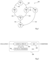
- FIG. 1 is a graph illustrating an example of a control flow 100 of a succession of sequences of software instructions.
- software represented by graph 100, is divided into six basic blocks BBi, i being an integer between 1 and 6. Each basic block corresponds to a vertex vi of graph 100.
- Each basic block is a linear sequence of consecutive software instructions containing no branches except at the very end. Thus, a basic block is always executed sequentially and unitarily.
- a transfer of control can take place. For example, an edge connects the base block BB2 to the base block BB1. A transfer of control can then take place between the base block BB1 to the base block BB2.
- control flow graph 100 illustrates the possible software execution paths.
- Control flow integrity verification techniques make it possible to verify that an executed path conforms to the corresponding control flow graph.
- the checks are carried out according to the control flow graph in order to guarantee that each basic block of the graph is correctly executed by the processor and that each transition from a basic block to another basic block corresponds to an edge of the graph.
- the reference values are for example precalculated before the execution of the software, for example during its programming. Each time the software is run, this data is recalculated to be compared with the precalculated reference values. If a basic block has been modified or if an invalid transfer of control has been carried out, the recalculated data does not correspond to the reference values, and the device triggers, for example, an alarm signal.
- a reference value is calculated on the basis of the sequence of instructions constituting the basic block.
- the reference value is a signature value or a checksum.
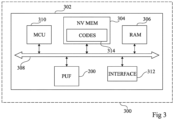
- FIG. 2 is a block diagram illustrating a physically unclonable function (PUF).
- PEF physically unclonable function
- an integrated circuit 200 includes a logic circuit 202 (LOGICAL CIRCUIT).
- the logic circuit 202 receives, for example, a challenge (CHALLENGE) and returns a response (RESPONSE) depending on the challenge and one or more physical or analog parameters 204 (PHYSICAL DISORDER).
- the parameter(s) 204 represent at least one physical variation taking place for example during the manufacturing of the circuit 200.
- the parameter(s) 204 are linked to the manufacturing of a semiconductor component of the circuit 200.
- the response generated will be different from one integrated circuit 200 to another.
- the PUF response is based on a manufacturing hazard, there is no correlation between two outputs, resulting from two different challenges.
- the physical or analog parameter(s) on which a PUF is based may be sensitive to external conditions such as for example temperature or humidity as well as for example to the aging of the circuit 200.
- the logic circuit 202 provides for example a first response to an additional circuit (ECC) 206 configured to correct the first response and provide the response.
- ECC error correction code
- the additional circuit 206 includes an error correction code (ECC).
- ECC error correction code
- PUFs for example known to those skilled in the art as “digital PUFs”, which are not sensitive to these disturbances and which therefore do not require correction.
- FIG. 3 represents, very schematically and in block form, an electronic device 300 comprising an integrated circuit 302 according to one embodiment of the present description.
- the electronic device 300 is for example an electronic card such as a microcircuit card, hardware for computer use, a microprocessor circuit, etc.
- the integrated circuit 302 comprises for example a non-volatile memory 304 (NV MEM), for example a flash memory and a volatile memory 306 (RAM), for example a random access memory (from the English “Random Access Memory”).
- NV MEM non-volatile memory
- RAM volatile memory
- the memories 304 and 306 are for example connected, via a bus 308, to a processor 310 (MCU).
- the bus 308 includes for example a data bus and a control bus.
- the bus 308 is an SPI interface (English “Serial Peripheral Interface”) or an I2C bus (English “Inter-Integrated Circuit”).
- the integrated circuit 302 comprises for example the circuit 200 (PUF) implementing a physically non-clonable function, for example a robust physically non-clonable function, connected to the bus 308.
- the integrated circuit 302 for example further comprises an interface 312 (INTERFACE).
- the non-volatile memory 304 includes for example software 314 (CODES), such as for example start-up codes and/or application codes of the device 300.
- CODES software 314
- reference values of the software 314 are calculated by the PUF 200 from values generated on the basis of software 314.
- the reference values are calculated by applying the PUF 200 to the checksums of one or more operands of one or more basic blocks of the software 314.
- the calculated reference values are then stored in the volatile memory 306.
- verification values are calculated, by applying the PUF 200 to the values generated from the software loaded in the volatile memory 306. The verification values thus obtained are compared to the reference values previously stored, for example, in the volatile memory 306.
- an image of the PUF 200 is stored in a memory of an external device, such as for example a database (not shown ) of the device 300.
- the image is for example stored in the memory of the external device before the installation of the software 314 in the non-volatile memory 304.
- reference values are for example obtained following a request to the memory of the external device and are stored in the non-volatile memory 304.
- FIG. 4 is a flowchart representing operations of a software integrity verification method according to an example of the present description.
- a first step 401 (LOADING IN RAM)
- the software 314 is for example loaded from the memory not volatile 304 to volatile memory 306 in order to be executed.
- a value associated with the software 314 is for example generated by the processor 310 in a step 402 (EXTRACTION INFORMATION).
- the value is generated from a section of the software 314 corresponding for example to a sequence of instructions and/or operands of a basic block of the control flow graph describing the software 314 .
- the value generated corresponds to a checksum following instructions and/or operands of software 314.
- a verification value is then obtained, in a step 403 (PUF REQUEST).
- the verification value is for example obtained by providing the value generated by the processor 310 as a challenge to the PUF 200.
- a step 404 the verification value obtained in step 403 is compared, for example by the processor 310, with the reference value stored in the non-volatile memory 304 or in the volatile memory 306.
- the reference value stored in the non-volatile memory 304 or in the volatile memory 306.
- an identifier is assigned to each basic block and each reference value is stored in association with the identifier of the basic block that it protects.
- the processor 110 uses for example the identifier of the part of the software considered to find the corresponding reference value in the memory.
- the software is instrumented upstream in order to incorporate the reference values. In this example, the reference values do not need to be stored in a memory of the device 300.
- step 404 the verification value differs from the reference value (branch N)
- this reflects the fact that the software section 314 checked does not correspond to what it should be.
- step 405 the integrated circuit 302 generates, for example, an alert signal.
- the alert signal interrupts the execution of software loaded in volatile memory 306.
- step 404 In the case where, during the execution of step 404, it is determined that the verification value is equal to the reference value (branch Y), the process continues in a step 406 (SOFTWARE EXECUTION) in which the verified software section 314 is executed by the processor 310.
- step 406 SOFTWARE EXECUTION
- FIG. 5 is a flowchart representing the operations of a software integrity verification method 314 according to another example of the present description.
- the integrity verification process illustrated in Figure 5 includes three phases 500 (OFFLINE), 502 (OFFLINE/ONLINE) and 504 (ONLINE).
- Phase 500 is for example carried out by the device 300 directly following the installation of software 314 in the non-volatile memory 304. In other embodiments, phase 500 is carried out by the device external to the device 300 comprising the memory in which an image of the PUF 200 is saved. Phase 500 comprises for example steps 506, 507, 508 and 509.
- step 506 CRITICAL SECTIONS IDENTIFICATION
- sections to be monitored in software 314 are identified.
- a section corresponds for example to a series of instructions or operands forming a basic block of software 314.
- the sections concerned present content sensitive and/or critical in terms of confidentiality.
- all of the software 314 is defined as being critical, and carrying out step 506 is then optional.
- step 507 CONTROL FLOW SELECTION
- a control flow of the sections identified in step 506 and in accordance with the flow control graph is selected.
- step 508 the sections of software 314 identified in step 506 are for example instrumented. In another example, all of the software 314 is instrumented.
- the instrumentation of all software 314, or critical sections of software 314, consists of the addition of instructions allowing the implementation of the verification process described in relation to the Figure 4 . For example, these instructions are added to each basic block of software 314 or only to the software sections identified in step 506.
- step 509 values, such as for example checksums, are generated, for example by the processor 310, for each section of the software 314 instrumented.
- values such as for example checksums
- the reference values are generated following the application of a hashing function taking for example as input the sequence of instructions composing each basic block or each section of the software to be protected.
- the reference values are generated by application of control-flow integrity (CFI) techniques known to those skilled in the art.
- CFI control-flow integrity
- Phase 502 corresponds to obtaining the reference values by application of the PUF 200 and their storage. Phase 502 is for example carried out by the device 300. In other embodiments, phase 502 is carried out by the external device. Phase 502 includes for example steps 510 and 511.
- step 510 the values generated in step 509 are for example provided as a challenge to the PUF 200.
- the PUF 200 then generates, one by one, reference values corresponding to the responses corresponding to the values generated data provided.
- the values generated by the processor 310 from the same sequence of instructions will be the same, but the responses of the two PUFs 200 will be different.
- the external device in the case where, in step 510, the values are generated by the external device, the external device is for example configured to communicate with the memory of the external device in which an image of the PUF 200 is saved The external device is then configured to determine the response value of the PUF 200 when the challenge matches the generated values.
- each reference value is stored in association with an identifier of the section of the software that it protected.
- the software is instrumented upstream in order to incorporate the reference values.
- the reference values do not need to be stored in a memory of the device 300.
- the reference values are stored in the non-volatile memory 304.
- Phase 502 is then called “offline” (OFFLINE).
- OFFLINE offline
- the storage of reference values in the non-volatile memory 304 is for example carried out when an image of the PUF 200 has for example been saved in a memory of the external device.
- the reference values then correspond to the version of software 314 stored in the non-volatile memory.
- the reference values are stored in the volatile memory 306.
- Phase 502 is then called “ONLINE”, that is to say it is carried out each time the software is loaded. 314 in the volatile memory 306, for example each time the device 300 is started.
- the reference values then correspond to the version of the software 314 loaded in the volatile memory 306.
- the values of reference may vary from one start of the device 300 to another. This is for example possible by varying the sections identified during step 506, and/or by introducing other variations in the calculation of the reference values.
- Phase 504 corresponds to checking the integrity of software 314 before their execution.
- the software 314 is then in the volatile memory 306 which is for example a less secure memory than the non-volatile memory 304.
- Phase 504 includes for example steps 402 and 403 as well as steps 514 and 515.
- Phase 504 comprises the sequence of steps 402 and 403 of the figure 4 in which one or more values are generated, for example by the processor 310 and from one of the software sections 314 having been instrumented in step 508. These values correspond for example to the checksum of the software section 314 considered.
- the corresponding verification value is then obtained, for example by providing the generated value(s) in step 402 as challenge values to PUF 200.
- the verification value then corresponds to the response returned by PUF 200.
- Step 514 is identical to step 404 and consists of comparing the verification value obtained in step 403 with the reference value corresponding to the section of software 314 considered and stored in memory 304 or 306 during step 511.
- Step 515 (ALERT SIGNAL OR EXECUTION) corresponds to step 405 or step 406 depending on the result of the comparison carried out in step 514.
- FIGS. 6A to 6C represent steps of the software integrity verification method according to the embodiment in which an image of the PUF 200 is saved in a memory of an external device.
- FIG. 6A represents a first step of a software integrity verification process 314.
- the Figure 6A represents the step of saving an image of the PUF 200 of the circuit 302 in a memory 600 of an external device. This step is for example carried out by the external device (not illustrated).
- the memory 600 of the external device is a database containing a plurality of PUF images (PUF A, PUF i, PUF N) coming from a plurality of circuits similar to circuit 302.
- the image of the PUF 200 is for example stored in association with an identifier (PUF i) of the PUF 200.
- the image of the PUF 200 contained in the memory 600 of the external device includes for example all of the challenge-response pairs associated with the PUF 200.
- This step of saving the image of the PUF 200 in the memory 600 of the external device is for example carried out before programming the software 314. This step is for example carried out directly following the manufacture of the circuit 302.
- FIG. 6B represents a second step of a software integrity verification process 314. This step is for example carried out by the external device.
- the Figure 6B illustrates step 508 of the Figure 5 software instrumentation 314.
- a critical section 602 is for example identified.
- the instrumentation of section 602 consists, for example, of the addition of a START ANALYSIS instruction, indicating for example that the lines of instructions following this instruction will be analyzed.
- the instrumentation of section 602 also consists, for example, of the addition of a CHECKSUM instruction allowing the generation of a value, corresponding for example to the checksum of the sequence of instructions contained between the START ANALYSIS instruction and the CHECKSUM statement.
- a 604 code illustrates the instrumented version of the 602 code.
- FIG. 6C represents a third step of a software integrity verification process 314.
- the Figure 6C illustrates an “offline” realization of steps 508 to 510 of the Figure 5 .
- the external device is configured to generate a value from the instrumented section 604, such as for example the checksum of section 604.
- the external device is for example configured to transmit the value generated in association from the PUF identifier i of the PUF 200 to the memory 600 of the external device to determine the response value of the PUF 200 when the challenge matches the generated value.
- the response value is transmitted by the external device to the electronic device 300.
- the response value is then for example stored in the non-volatile memory 304 as a reference value for section 602.
- the external device is for example configured to modify section 604 into a section 606 by for example replacing the CHECKSUM instruction with a PUFi(CHECKSUM) instruction.
- the section 606 is then transmitted to the device 300 and stored, for example, in the non-volatile memory 304.
- the modification has the effect of controlling, during a compilation of the section 606, the calculation by the PUF 200 of the device 300 of the corresponding answer to the CHECKSUM challenge.
- This embodiment allows for example a user to protect software that he adds, for example in a personalization step of the device 300.
- the integrity check carried out in phase 504 is carried out between the version of the software 314 stored in the volatile memory 304 with that loaded in the volatile memory 306. This embodiment therefore makes it possible to detect attacks on non-volatile memory 304.
- FIGS 7A and 7B represent steps of the integrity verification method according to the embodiment in which the reference values are calculated each time the software 314 is loaded into the volatile memory 306.
- FIG. 7A represents a first step of a software integrity verification process 314.
- FIG. 7A illustrates the instrumentation step 508 of section 602 in section 604 and is identical to the step described in relation to the Figure 6B .
- section 604 is for example stored in non-volatile memory 304.
- FIG. 7B represents a second step of a software integrity verification process 314.
- Figure 7B illustrates an “on-line” implementation of step 510.
- the software 314 when starting the device 300, or more particularly when starting the processor 310, the software 314 is read in the non-volatile memory 304 and is loaded into the volatile memory 306.
- the sequences of software instructions 314 are analyzed, for example by another software (not shown), in order to identify the critical sections, including section 602, identified, for example in step 506.
- a value is generated, such as by example the checksum, from section 604 and is transmitted, by the processor 310 to the PUF 200 of the circuit 302.
- the response value of the PUF 200 is then stored in the volatile memory 306.
- the section 604 is for example modified into section 706 to include the PUF(CHECKSUM) instruction controlling the calculation of the check value of section 602, using PUF 200 of circuit 302.
- Section 706 is loaded into volatile memory 306 in order to be executed, the compilation of section 706 generating the calculation of the verification value.
- the circuit 302 further comprises a random number generator (not shown in Figure 3 ).
- a random number is generated by the random number generator, the random number generator being for example configured to never generate the same random number several times in a row.
- steps 403 and 511 include the concatenation of the random number with the value generated from sections 604 or 706. The challenges provided in steps 403 and 511 to PUF 200, and therefore the corresponding responses of the PUF 200, then depend on the startup of processor 310.
- the circuit 302 further comprises a stopwatch (in English "timer") (not shown), which is for example produced by a counter, and which is configured to, when a predefined delay is reached, transmit a signal to the processor 310.
- the stopwatch is clocked by the system clock of the device 300.
- the processor 310 is then for example configured to, upon reception of this signal, verify that the calculation of the reference values and/or or verification has taken place. This makes it possible to prevent a modification, for example deleting the START VERIFY, CHECKSUM and/or PUF (CHECKSUM) instructions from the instrumented section 604 when it is still stored in the non-volatile memory 304.
- FIG 8 represents, very schematically and in block form, a software implementation 800 of the processor 310 according to an embodiment of the present description.
- the software implementation 800 allows the implementation of the verification method described in relation to the Figure 4 .
- the processor 310 includes a secure zone 302 (SECURED ENVIRONMENT) and an unsecured zone 304 (NON SECURED ENVIRONMENT).
- SECURED ENVIRONMENT SECURED ENVIRONMENT
- NON SECURED ENVIRONMENT NON SECURED ENVIRONMENT
- the instrumented section 606 is loaded in the unsecured zone 804 of the processor 310.
- the “online” phase 504 is then implemented in software by the secure zone 802.
- information relating to section 606 and/or section 706 is transmitted to the secure zone 802, allowing the initiation (INIT) of phase 504.
- a finite state machine for example implemented in software in the secure zone 802, then allows the calculation of a value, such as the checksum of code 706 and/or code 706, and allows the verification of the control flow information of section 606 and /or section 706.
- the value generated by the finite state machine is then transmitted to the PUF 200 via bus 308 in order to obtain the verification value.
- the PUF 200 is then implemented in hardware in the circuit 302, but outside the processor 310.
- the secure zone 302 When the verification value, returned by the PUF 200, for example via the bus 308, differs from the reference value, stored for example in the non-volatile memory 304, the secure zone 302 generates for example a signal. ALERT alert.
- FIG. 9 represents, very schematically and in block form, a hardware implementation 900 of the circuit 302 according to an embodiment of the present description in which the circuit is produced by a system on chip (in English “System on Chip, SoC”) .
- the hardware implementation 900 allows the realization of the verification method described in relation to the figure 4 .
- Circuit 302 includes for example an application processor 902 (APPLICATIVE PROCESSOR).
- the processor 310 described in relation to the Figure 3 implements the application processor 902.
- the circuit 302 further comprises a zone 904 comprising the PUF 200.
- the zone 904 further comprises a set 906 of sub-circuits allowing the hardware implementation of phase 504.
- the assembly 906 is then configured to extract information from the section 606 and/or the section 706 loaded for execution in the application processor 902.
- the assembly 906 is further configured to generate the verification value as well as to compare it with the corresponding reference value, for example stored in the volatile memory 306.
- An advantage of the embodiments described is that the reference values protecting the critical sections of one or more software codes are generated from the physically non-clonable function of the associated device.
- the physically non-clonable function is such that the reference values for the same software codes are different from one device to another, which allows individualized security of each electronic device.
- Another advantage of the described embodiments is obtained when the implemented PUF is a robust PUF.
- the set of “challenge-response” peers being large, it is not possible for an attacker of the device to know the entire image of the PUF.
- Another advantage of the embodiments described is that the use of a memory of an external device storing an image of the PUF also makes it possible to ensure the authenticity of the protected software.
- Another advantage of the embodiments described is that, when phase 502 is carried out online, the reference values can differ from one startup of the device to another, thus complicating the task of an attacker.
- phase 504 can be implemented in software and hardware.
Landscapes
- Engineering & Computer Science (AREA)
- Computer Security & Cryptography (AREA)
- Theoretical Computer Science (AREA)
- Computer Hardware Design (AREA)
- Physics & Mathematics (AREA)
- Software Systems (AREA)
- General Engineering & Computer Science (AREA)
- General Physics & Mathematics (AREA)
- Signal Processing (AREA)
- Computer Networks & Wireless Communication (AREA)
- Health & Medical Sciences (AREA)
- Bioethics (AREA)
- General Health & Medical Sciences (AREA)
- Mathematical Physics (AREA)
- Test And Diagnosis Of Digital Computers (AREA)
- Tests Of Electronic Circuits (AREA)
- Detection And Correction Of Errors (AREA)
Applications Claiming Priority (1)
| Application Number | Priority Date | Filing Date | Title |
|---|---|---|---|
| FR2207125A FR3137988B1 (fr) | 2022-07-12 | 2022-07-12 | Procédé et circuit pour la vérification de l’intégrité d’un logiciel |
Publications (1)
| Publication Number | Publication Date |
|---|---|
| EP4307143A1 true EP4307143A1 (de) | 2024-01-17 |
Family
ID=83996646
Family Applications (1)
| Application Number | Title | Priority Date | Filing Date |
|---|---|---|---|
| EP23184505.8A Pending EP4307143A1 (de) | 2022-07-12 | 2023-07-10 | Verfahren und schaltungsanordnung zur überprüfung der integrität von software |
Country Status (3)
| Country | Link |
|---|---|
| US (1) | US20240020422A1 (de) |
| EP (1) | EP4307143A1 (de) |
| FR (1) | FR3137988B1 (de) |
Citations (2)
| Publication number | Priority date | Publication date | Assignee | Title |
|---|---|---|---|---|
| EP3373178A1 (de) * | 2017-03-08 | 2018-09-12 | Secure-IC SAS | Vergleich von ausführungkontextdaten signaturen mit referenzen |
| US20210081569A1 (en) * | 2019-09-13 | 2021-03-18 | Arizona Board of Regent on Behalf of Northern Arizona University | Puf-based data integrity |
Family Cites Families (9)
| Publication number | Priority date | Publication date | Assignee | Title |
|---|---|---|---|---|
| US7032106B2 (en) * | 2001-12-27 | 2006-04-18 | Computer Network Technology Corporation | Method and apparatus for booting a microprocessor |
| US7370190B2 (en) * | 2005-03-03 | 2008-05-06 | Digimarc Corporation | Data processing systems and methods with enhanced bios functionality |
| US8051299B2 (en) * | 2006-03-20 | 2011-11-01 | Hewlett-Packard Development Company, L.P. | Computer security method and computer system |
| WO2014138626A1 (en) * | 2013-03-08 | 2014-09-12 | Robert Bosch Gmbh | Systems and methods for maintaining integrity and secrecy in untrusted computing platforms |
| US9755831B2 (en) * | 2014-01-22 | 2017-09-05 | Qualcomm Incorporated | Key extraction during secure boot |
| KR101593166B1 (ko) * | 2014-06-02 | 2016-02-15 | 한국전자통신연구원 | 물리적 복제 방지 함수의 오류를 방지하는 장치 및 그 방법 |
| US9697359B2 (en) * | 2015-04-15 | 2017-07-04 | Qualcomm Incorporated | Secure software authentication and verification |
| US12255994B2 (en) * | 2021-06-07 | 2025-03-18 | Micron Technology, Inc. | Secure data storage with a dynamically generated key |
| US11889002B2 (en) * | 2021-09-23 | 2024-01-30 | Rockwell Automation Technologies, Inc. | Use of physical unclonable functions to prevent counterfeiting of industrial control products |
-
2022
- 2022-07-12 FR FR2207125A patent/FR3137988B1/fr active Active
-
2023
- 2023-07-09 US US18/349,156 patent/US20240020422A1/en active Pending
- 2023-07-10 EP EP23184505.8A patent/EP4307143A1/de active Pending
Patent Citations (2)
| Publication number | Priority date | Publication date | Assignee | Title |
|---|---|---|---|---|
| EP3373178A1 (de) * | 2017-03-08 | 2018-09-12 | Secure-IC SAS | Vergleich von ausführungkontextdaten signaturen mit referenzen |
| US20210081569A1 (en) * | 2019-09-13 | 2021-03-18 | Arizona Board of Regent on Behalf of Northern Arizona University | Puf-based data integrity |
Non-Patent Citations (2)
| Title |
|---|
| HAMADEH HALA ET AL: "Physical Unclonable Functions (PUFs) Entangled Trusted Computing Base", 2019 IEEE INTERNATIONAL SYMPOSIUM ON SMART ELECTRONIC SYSTEMS (ISES) (FORMERLY INIS), IEEE, 16 December 2019 (2019-12-16), pages 177 - 180, XP033718461, DOI: 10.1109/ISES47678.2019.00047 * |
| HAMADEH HALA ET AL: "Probabilistic Verification of Outsourced Computation Based on Novel Reversible PUFs", 27 March 2020, 16TH EUROPEAN CONFERENCE - COMPUTER VISION - ECCV 2020, CORNELL UNIVERSITY LIBRARY, 201 OLIN LIBRARY CORNELL UNIVERSITY ITHACA, NY 14853, PAGE(S) 30 - 37, XP047546746 * |
Also Published As
| Publication number | Publication date |
|---|---|
| FR3137988A1 (fr) | 2024-01-19 |
| FR3137988B1 (fr) | 2024-06-21 |
| US20240020422A1 (en) | 2024-01-18 |
Similar Documents
| Publication | Publication Date | Title |
|---|---|---|
| EP3457620A1 (de) | Ausführungsverfahren eines binären codes einer durch einen mikroprozessor gesicherten funktion | |
| EP3610372B1 (de) | Verfahren zum ausführen eines maschinencodes einer sicheren funktion | |
| EP3033857B1 (de) | Binärcode-authentifizierung | |
| EP2656268A1 (de) | Schutz von applets vor analysen verdeckter kanäle | |
| EP1983436B1 (de) | Kontrolle der Integrität eines prozessorexternen Speichers | |
| EP1724700A1 (de) | Kontrolle der Integrität eines externen Prozessorspeichers | |
| EP2336931B1 (de) | Verfahren zur Unterschriftenprüfung | |
| EP4307143A1 (de) | Verfahren und schaltungsanordnung zur überprüfung der integrität von software | |
| WO2009071791A2 (fr) | Verification de donnees lues en memoire | |
| WO2004061622A2 (fr) | Procede pour la securisation des systemes informatiques incorporant un module d'interpretation de code. | |
| FR2963128A1 (fr) | Procédé de détection d'une attaque par injection de faute dans un dispositif de mémoire, et système de détection correspondant | |
| EP3284206B1 (de) | Verfahren zur sicherung der ausführung eines programms | |
| EP3392791B1 (de) | Verfahren zur ausführung eines programms, das zur interpretation durch eine virtuelle maschine bestimmt ist, die gegen angriffe durch fehler-injektion geschützt ist | |
| FR2867929A1 (fr) | Procede d'authentification dynamique de programmes par un objet portable electronique | |
| EP2860660A1 (de) | Gesichertes Ladesystem und -verfahren von Daten in einen mit einem gesicherten Prozessor verbundenen Cache-Speicher | |
| EP4057169A1 (de) | Verfahren zur ausführung eines binären codes eines computerprogramms durch einen mikroprozessor | |
| EP4632579A1 (de) | Verfahren zum schutz eines mikrokontrollers | |
| EP1770524A2 (de) | Feststellung von Sequenzfehlern in einer Programmausführung | |
| EP3295297B1 (de) | Verfahren zur sicherung eines vergleichs von daten während der ausführung eines programms | |
| CN113646760A (zh) | 一种软件程序运行检查方法、电子设备及存储介质 | |
| FR2974648A1 (fr) | Protection d'une memoire vive contre des attaques par injection de fautes | |
| FR2831739A1 (fr) | Procede de mise en oeuvre securisee d'un module fonctionnel, dans un composant electronique et composant correspondant | |
| FR2928754A1 (fr) | Carte a circuit integre ayant un programme d'exploitation modifiable et procede de modification correspondant | |
| EP2104893A2 (de) | Gesicherte elektronische systeme, sicherungsverfahren und verwendung solcher systeme | |
| FR2976697A1 (fr) | Transfert securise entre memoire non-volatile et memoire volatile |
Legal Events
| Date | Code | Title | Description |
|---|---|---|---|
| PUAI | Public reference made under article 153(3) epc to a published international application that has entered the european phase |
Free format text: ORIGINAL CODE: 0009012 |
|
| STAA | Information on the status of an ep patent application or granted ep patent |
Free format text: STATUS: REQUEST FOR EXAMINATION WAS MADE |
|
| 17P | Request for examination filed |
Effective date: 20230710 |
|
| AK | Designated contracting states |
Kind code of ref document: A1 Designated state(s): AL AT BE BG CH CY CZ DE DK EE ES FI FR GB GR HR HU IE IS IT LI LT LU LV MC ME MK MT NL NO PL PT RO RS SE SI SK SM TR |
|
| RAP3 | Party data changed (applicant data changed or rights of an application transferred) |
Owner name: COMMISSARIAT A L'ENERGIE ATOMIQUE ET AUX ENERGIESALTERNATIVES |
|
| STAA | Information on the status of an ep patent application or granted ep patent |
Free format text: STATUS: EXAMINATION IS IN PROGRESS |
|
| 17Q | First examination report despatched |
Effective date: 20251020 |