EP4309571A2 - Unité de surveillance et système de chirurgie haute fréquence comprenant une telle unité de surveillance - Google Patents
Unité de surveillance et système de chirurgie haute fréquence comprenant une telle unité de surveillance Download PDFInfo
- Publication number
- EP4309571A2 EP4309571A2 EP23214347.9A EP23214347A EP4309571A2 EP 4309571 A2 EP4309571 A2 EP 4309571A2 EP 23214347 A EP23214347 A EP 23214347A EP 4309571 A2 EP4309571 A2 EP 4309571A2
- Authority
- EP
- European Patent Office
- Prior art keywords
- frequency
- patient
- monitoring unit
- surgical device
- measuring
- Prior art date
- Legal status (The legal status is an assumption and is not a legal conclusion. Google has not performed a legal analysis and makes no representation as to the accuracy of the status listed.)
- Granted
Links
Images


Classifications
-
- A—HUMAN NECESSITIES
- A61—MEDICAL OR VETERINARY SCIENCE; HYGIENE
- A61B—DIAGNOSIS; SURGERY; IDENTIFICATION
- A61B18/00—Surgical instruments, devices or methods for transferring non-mechanical forms of energy to or from the body
- A61B18/04—Surgical instruments, devices or methods for transferring non-mechanical forms of energy to or from the body by heating
- A61B18/12—Surgical instruments, devices or methods for transferring non-mechanical forms of energy to or from the body by heating by passing a current through the tissue to be heated, e.g. high-frequency current
- A61B18/1206—Generators therefor
- A61B18/1233—Generators therefor with circuits for assuring patient safety
-
- A—HUMAN NECESSITIES
- A61—MEDICAL OR VETERINARY SCIENCE; HYGIENE
- A61B—DIAGNOSIS; SURGERY; IDENTIFICATION
- A61B18/00—Surgical instruments, devices or methods for transferring non-mechanical forms of energy to or from the body
- A61B18/04—Surgical instruments, devices or methods for transferring non-mechanical forms of energy to or from the body by heating
- A61B18/12—Surgical instruments, devices or methods for transferring non-mechanical forms of energy to or from the body by heating by passing a current through the tissue to be heated, e.g. high-frequency current
- A61B18/14—Probes or electrodes therefor
-
- A—HUMAN NECESSITIES
- A61—MEDICAL OR VETERINARY SCIENCE; HYGIENE
- A61B—DIAGNOSIS; SURGERY; IDENTIFICATION
- A61B18/00—Surgical instruments, devices or methods for transferring non-mechanical forms of energy to or from the body
- A61B18/04—Surgical instruments, devices or methods for transferring non-mechanical forms of energy to or from the body by heating
- A61B18/12—Surgical instruments, devices or methods for transferring non-mechanical forms of energy to or from the body by heating by passing a current through the tissue to be heated, e.g. high-frequency current
- A61B18/1206—Generators therefor
-
- A—HUMAN NECESSITIES
- A61—MEDICAL OR VETERINARY SCIENCE; HYGIENE
- A61B—DIAGNOSIS; SURGERY; IDENTIFICATION
- A61B18/00—Surgical instruments, devices or methods for transferring non-mechanical forms of energy to or from the body
- A61B18/04—Surgical instruments, devices or methods for transferring non-mechanical forms of energy to or from the body by heating
- A61B18/12—Surgical instruments, devices or methods for transferring non-mechanical forms of energy to or from the body by heating by passing a current through the tissue to be heated, e.g. high-frequency current
- A61B18/14—Probes or electrodes therefor
- A61B18/16—Indifferent or passive electrodes for grounding
-
- A—HUMAN NECESSITIES
- A61—MEDICAL OR VETERINARY SCIENCE; HYGIENE
- A61B—DIAGNOSIS; SURGERY; IDENTIFICATION
- A61B5/00—Measuring for diagnostic purposes; Identification of persons
- A61B5/05—Detecting, measuring or recording for diagnosis by means of electric currents or magnetic fields; Measuring using microwaves or radio waves
- A61B5/053—Measuring electrical impedance or conductance of a portion of the body
-
- A—HUMAN NECESSITIES
- A61—MEDICAL OR VETERINARY SCIENCE; HYGIENE
- A61B—DIAGNOSIS; SURGERY; IDENTIFICATION
- A61B5/00—Measuring for diagnostic purposes; Identification of persons
- A61B5/68—Arrangements of detecting, measuring or recording means, e.g. sensors, in relation to patient
- A61B5/6887—Arrangements of detecting, measuring or recording means, e.g. sensors, in relation to patient mounted on external non-worn devices, e.g. non-medical devices
- A61B5/6892—Mats
-
- A—HUMAN NECESSITIES
- A61—MEDICAL OR VETERINARY SCIENCE; HYGIENE
- A61B—DIAGNOSIS; SURGERY; IDENTIFICATION
- A61B17/00—Surgical instruments, devices or methods
- A61B2017/00017—Electrical control of surgical instruments
- A61B2017/00199—Electrical control of surgical instruments with a console, e.g. a control panel with a display
-
- A—HUMAN NECESSITIES
- A61—MEDICAL OR VETERINARY SCIENCE; HYGIENE
- A61B—DIAGNOSIS; SURGERY; IDENTIFICATION
- A61B18/00—Surgical instruments, devices or methods for transferring non-mechanical forms of energy to or from the body
- A61B2018/00571—Surgical instruments, devices or methods for transferring non-mechanical forms of energy to or from the body for achieving a particular surgical effect
- A61B2018/00577—Ablation
-
- A—HUMAN NECESSITIES
- A61—MEDICAL OR VETERINARY SCIENCE; HYGIENE
- A61B—DIAGNOSIS; SURGERY; IDENTIFICATION
- A61B18/00—Surgical instruments, devices or methods for transferring non-mechanical forms of energy to or from the body
- A61B2018/00571—Surgical instruments, devices or methods for transferring non-mechanical forms of energy to or from the body for achieving a particular surgical effect
- A61B2018/00589—Coagulation
-
- A—HUMAN NECESSITIES
- A61—MEDICAL OR VETERINARY SCIENCE; HYGIENE
- A61B—DIAGNOSIS; SURGERY; IDENTIFICATION
- A61B18/00—Surgical instruments, devices or methods for transferring non-mechanical forms of energy to or from the body
- A61B2018/00571—Surgical instruments, devices or methods for transferring non-mechanical forms of energy to or from the body for achieving a particular surgical effect
- A61B2018/00601—Cutting
-
- A—HUMAN NECESSITIES
- A61—MEDICAL OR VETERINARY SCIENCE; HYGIENE
- A61B—DIAGNOSIS; SURGERY; IDENTIFICATION
- A61B18/00—Surgical instruments, devices or methods for transferring non-mechanical forms of energy to or from the body
- A61B2018/00571—Surgical instruments, devices or methods for transferring non-mechanical forms of energy to or from the body for achieving a particular surgical effect
- A61B2018/00607—Coagulation and cutting with the same instrument
-
- A—HUMAN NECESSITIES
- A61—MEDICAL OR VETERINARY SCIENCE; HYGIENE
- A61B—DIAGNOSIS; SURGERY; IDENTIFICATION
- A61B18/00—Surgical instruments, devices or methods for transferring non-mechanical forms of energy to or from the body
- A61B2018/00636—Sensing and controlling the application of energy
- A61B2018/00666—Sensing and controlling the application of energy using a threshold value
-
- A—HUMAN NECESSITIES
- A61—MEDICAL OR VETERINARY SCIENCE; HYGIENE
- A61B—DIAGNOSIS; SURGERY; IDENTIFICATION
- A61B18/00—Surgical instruments, devices or methods for transferring non-mechanical forms of energy to or from the body
- A61B2018/00636—Sensing and controlling the application of energy
- A61B2018/00773—Sensed parameters
- A61B2018/00791—Temperature
-
- A—HUMAN NECESSITIES
- A61—MEDICAL OR VETERINARY SCIENCE; HYGIENE
- A61B—DIAGNOSIS; SURGERY; IDENTIFICATION
- A61B18/00—Surgical instruments, devices or methods for transferring non-mechanical forms of energy to or from the body
- A61B2018/00636—Sensing and controlling the application of energy
- A61B2018/00773—Sensed parameters
- A61B2018/00845—Frequency
-
- A—HUMAN NECESSITIES
- A61—MEDICAL OR VETERINARY SCIENCE; HYGIENE
- A61B—DIAGNOSIS; SURGERY; IDENTIFICATION
- A61B18/00—Surgical instruments, devices or methods for transferring non-mechanical forms of energy to or from the body
- A61B2018/00636—Sensing and controlling the application of energy
- A61B2018/00773—Sensed parameters
- A61B2018/00869—Phase
-
- A—HUMAN NECESSITIES
- A61—MEDICAL OR VETERINARY SCIENCE; HYGIENE
- A61B—DIAGNOSIS; SURGERY; IDENTIFICATION
- A61B18/00—Surgical instruments, devices or methods for transferring non-mechanical forms of energy to or from the body
- A61B2018/00636—Sensing and controlling the application of energy
- A61B2018/00773—Sensed parameters
- A61B2018/00875—Resistance or impedance
-
- A—HUMAN NECESSITIES
- A61—MEDICAL OR VETERINARY SCIENCE; HYGIENE
- A61B—DIAGNOSIS; SURGERY; IDENTIFICATION
- A61B18/00—Surgical instruments, devices or methods for transferring non-mechanical forms of energy to or from the body
- A61B2018/00636—Sensing and controlling the application of energy
- A61B2018/00773—Sensed parameters
- A61B2018/00892—Voltage
-
- A—HUMAN NECESSITIES
- A61—MEDICAL OR VETERINARY SCIENCE; HYGIENE
- A61B—DIAGNOSIS; SURGERY; IDENTIFICATION
- A61B18/00—Surgical instruments, devices or methods for transferring non-mechanical forms of energy to or from the body
- A61B2018/00636—Sensing and controlling the application of energy
- A61B2018/00898—Alarms or notifications created in response to an abnormal condition
-
- A—HUMAN NECESSITIES
- A61—MEDICAL OR VETERINARY SCIENCE; HYGIENE
- A61B—DIAGNOSIS; SURGERY; IDENTIFICATION
- A61B18/00—Surgical instruments, devices or methods for transferring non-mechanical forms of energy to or from the body
- A61B18/04—Surgical instruments, devices or methods for transferring non-mechanical forms of energy to or from the body by heating
- A61B18/12—Surgical instruments, devices or methods for transferring non-mechanical forms of energy to or from the body by heating by passing a current through the tissue to be heated, e.g. high-frequency current
- A61B18/14—Probes or electrodes therefor
- A61B18/16—Indifferent or passive electrodes for grounding
- A61B2018/165—Multiple indifferent electrodes
-
- A—HUMAN NECESSITIES
- A61—MEDICAL OR VETERINARY SCIENCE; HYGIENE
- A61B—DIAGNOSIS; SURGERY; IDENTIFICATION
- A61B18/00—Surgical instruments, devices or methods for transferring non-mechanical forms of energy to or from the body
- A61B18/04—Surgical instruments, devices or methods for transferring non-mechanical forms of energy to or from the body by heating
- A61B18/12—Surgical instruments, devices or methods for transferring non-mechanical forms of energy to or from the body by heating by passing a current through the tissue to be heated, e.g. high-frequency current
- A61B18/14—Probes or electrodes therefor
- A61B18/16—Indifferent or passive electrodes for grounding
- A61B2018/167—Passive electrodes capacitively coupled to the skin
-
- A—HUMAN NECESSITIES
- A61—MEDICAL OR VETERINARY SCIENCE; HYGIENE
- A61B—DIAGNOSIS; SURGERY; IDENTIFICATION
- A61B2560/00—Constructional details of operational features of apparatus; Accessories for medical measuring apparatus
- A61B2560/02—Operational features
- A61B2560/0266—Operational features for monitoring or limiting apparatus function
-
- A—HUMAN NECESSITIES
- A61—MEDICAL OR VETERINARY SCIENCE; HYGIENE
- A61B—DIAGNOSIS; SURGERY; IDENTIFICATION
- A61B2560/00—Constructional details of operational features of apparatus; Accessories for medical measuring apparatus
- A61B2560/04—Constructional details of apparatus
- A61B2560/0462—Apparatus with built-in sensors
- A61B2560/0468—Built-in electrodes
-
- A—HUMAN NECESSITIES
- A61—MEDICAL OR VETERINARY SCIENCE; HYGIENE
- A61B—DIAGNOSIS; SURGERY; IDENTIFICATION
- A61B2562/00—Details of sensors; Constructional details of sensor housings or probes; Accessories for sensors
- A61B2562/02—Details of sensors specially adapted for in-vivo measurements
- A61B2562/0271—Thermal or temperature sensors
-
- A—HUMAN NECESSITIES
- A61—MEDICAL OR VETERINARY SCIENCE; HYGIENE
- A61B—DIAGNOSIS; SURGERY; IDENTIFICATION
- A61B5/00—Measuring for diagnostic purposes; Identification of persons
- A61B5/01—Measuring temperature of body parts ; Diagnostic temperature sensing, e.g. for malignant or inflamed tissue
-
- A—HUMAN NECESSITIES
- A61—MEDICAL OR VETERINARY SCIENCE; HYGIENE
- A61B—DIAGNOSIS; SURGERY; IDENTIFICATION
- A61B5/00—Measuring for diagnostic purposes; Identification of persons
- A61B5/48—Other medical applications
- A61B5/4848—Monitoring or testing the effects of treatment, e.g. of medication
-
- A—HUMAN NECESSITIES
- A61—MEDICAL OR VETERINARY SCIENCE; HYGIENE
- A61B—DIAGNOSIS; SURGERY; IDENTIFICATION
- A61B5/00—Measuring for diagnostic purposes; Identification of persons
- A61B5/74—Details of notification to user or communication with user or patient; User input means
- A61B5/746—Alarms related to a physiological condition, e.g. details of setting alarm thresholds or avoiding false alarms
Definitions
- the present invention relates to a monitoring unit that is set up to monitor a patient during operation of a high-frequency surgical device and a high-frequency surgery system with such a monitoring unit.
- High-frequency surgery is sometimes a dominant form of electrosurgery. It includes the (assistant) use of electrical energy for the (targeted) thermally induced change and/or destruction of tissue cells in order to achieve so-called hemostasis (stopping bleeding), tissue cutting and/or sealing (coagulation).
- High-frequency alternating current e.g. 0.3 to 4 MHz
- electrodes or applicators
- the electrical tissue resistance present in the tissue leads to a thermal tissue interaction, which will be discussed again below.
- the so-called current density (physical unit: ampere per cm 2 ) can be assigned a key role in HF surgery technology, with the electrical current density colloquially indicating how closely packed an electrical current flows.
- the current density therefore also characterizes, for example, the loading of an electrical conductor (in the case of HF surgery, represented by animal or human tissue) by an electrical (alternating) current.
- the current density is defined as the ratio of the current intensity I to the cross-sectional area A available to the current.
- coagulation precipitation, flocculation or coagulation of a substance
- coagulation precipitation, flocculation or coagulation of a substance
- tissue When cutting tissue using high-frequency alternating current, locally high current densities can be generated in the tissue (section) to be cut, preferably via small-area, knife- or needle-shaped electrodes.
- the tissue treated by the high-frequency alternating current suddenly heats up to over 100 °C, so that the resulting vapor pressure explosively tears the cell membranes of the tissue cells.
- the resulting electrically insulating vapor between the electrode and the tissue subsequently prevents the unimpeded flow of ohmic current into the tissue, so that a voltage (so-called cutting voltage) builds up between the electrode and the tissue, which causes sparks to form between the electrode and the tissue .
- a further energy input then takes place via sparks.
- HF current produces in the treated tissue is essentially determined by its duration of action, voltage level and a degree of amplitude modulation.
- the frequency (0.3 to 5 MHz), however, does not play a major role.
- An important parameter is the so-called crest factor. It describes the ratio of the peak value to the effective value of an electrical alternating variable and provides an indication of how strongly a current is modulated in its amplitude.
- crest factor a sinusoidal alternating voltage with an effective value (U eff ) of 230 V eff (mains voltage) has a peak value (U p ) of approx. 325 V p , so that the crest factor (C F ) here is 1.41 ( ⁇ 2). .
- the output power is constant, the output voltage must also be higher for a current with a high crest factor.
- the "heart" of HF surgery technology is formed by a so-called high-frequency generator, whereby the underlying technology has steadily improved over the past decades, particularly driven by a variety of microprocessor and control technology developments.
- a generator-feeding mains current is converted into a high-frequency current (necessary for HF surgery).
- the high-frequency output power of the HF surgical devices is constantly being reduced, driven by safety-related standardization and technical development (e.g. through the standardization (IEC 60601-2-2)) and is also limited to an upper limit of 400 W.
- IEC 60601-2-2 recommends using working frequencies above 300 kHz and below 5 MHz.
- a potential “source” of undesirable burns and/or chemical burns is often improper handling of the preparation of the patient in advance of the operation, for example by improperly positioning (or placing) the patient on an operating table or chair.
- An attempt is made to counteract this incorrect operation or incorrect handling (human error) by defining and standardizing a large number of safety-relevant application rules, which, depending on the operating environment, is successful, but does not completely prevent the occurrence of burns and chemical burns on the patient.
- the monopolar HF surgery technique has an active electrode and a neutral surface electrode, each of which is connected to the HF generator.
- the physical effects (cutting, coagulation) necessary for HF surgery are generated at the active electrode.
- the neutral electrode which has a larger surface area than the active electrode, is placed, for example, on a thigh or an upper arm of the patient.
- the high-frequency alternating current introduced by the active electrode is ideally completely dissipated via the neutral electrode.
- the rest of the patient's body is ideally positioned in an electrically insulated manner.
- both the active and the neutral electrode are in one instrument, e.g. B. a bipolar tweezers with mutually insulated legs (branches), integrated.
- the high-frequency alternating current flows into the tissue via the active electrode and back to the HF generator via the neutral electrode.
- the bipolar technique guarantees a higher degree of safety compared to the monopolar technique, especially in neurological fine preparations.
- the risk of unwanted burns and/or chemical burns on the patient e.g. B. by touching conductive objects during the operation, rather low, but not excluded.
- the object is achieved according to a first aspect of the invention by a monitoring unit which is set up to monitor a patient during operation of a high-frequency surgical device.
- the high-frequency surgical device is designed to separate and/or coagulate biological tissue (of the patient) using high-frequency electrical energy.
- the monitoring unit according to the invention has measuring electrodes which are arranged in a periphery of the patient, and an evaluation and control unit which is set up to impress a predetermined measuring alternating voltage or a predetermined measuring alternating current into the measuring electrodes, and a voltage drop between the measuring electrodes To measure impedance, and to monitor a time course of the impedance and/or a change in it over time.
- the evaluation and control unit is set up to generate a warning signal when a relative change in the impedance in the course of the impedance falls below or exceeds a predetermined first limit value and/or the impedance falls below a predetermined second limit value.
- the monitoring unit according to the invention has the advantage that, by means of the impedance measurement and monitoring of the patient's periphery, the patient is protected from undesirable burns and/or chemical burns on tissue parts that are not actually affected by the surgical procedure (e.g. caused by uncontrolled leakage currents and/or leakage currents). e.g. on a foot, a hand and/or parts of the patient's back).
- the impedance measurement enables, so to speak, a prediction of an impending burn and/or chemical burn, which can be indicated by issuing the warning signal, so that, for example, the surgeon or auxiliary personnel can intervene manually.
- the high-frequency surgical device can be switched off in a controlled manner using the evaluation and control unit or using a high-frequency generator.
- the high-frequency surgical device preferably has an active electrode and a neutral electrode, with at least the active electrode being connected to a preferably present high-frequency generator.
- the active electrode is designed to separate and/or coagulate biological tissue using high-frequency electrical energy
- the neutral electrode is designed to derive high-frequency electrical energy from the biological tissue.
- the neutral electrode is preferably also connected to the high-frequency generator.
- An uncontrolled high-frequency current flow over a section of tissue or a part of tissue in the periphery of the operating zone can, for example, be caused by improper positioning of the patient on the operating table.
- a (accidental) contact with surgical equipment that is conductive in the high-frequency range can result in the formation of a so-called line bridge, over which at least part or (in the worst case) all of the via the Active electrode introduced alternating current can flow.
- the cutting current introduced via the active electrode should flow exclusively via the neutral electrode.
- the phrase “in a periphery of the patient” is understood to mean that the measuring electrodes (preferably a plurality of measuring electrodes, but at least more than one measuring electrode) are arranged in an immediate and/or indirect environment of the operation center and/or on or around the patient are.
- the measuring electrodes can, for example, be arranged (regularly) distributed over a (preferably entire) support surface on an operating support on which the patient is supported during the operation.
- the measuring electrodes can be arranged on surgical equipment (ventilation and suction tubes, cabling, etc.) in the patient's periphery. It is preferred that the measuring electrodes are arranged on surfaces that are in direct contact with a part of the body or the skin of the patient (e.g. the back area by placing it directly on the operating table) and / or that are potentially in contact with a section of tissue (or a Body part) of the patient can come into contact (e.g. if the patient's hand is improperly positioned, the patient's hand slips off the operating table and the hand subsequently comes into contact with, for example, a breathing tube).
- surgical equipment ventilation and suction tubes, cabling, etc.
- the measuring electrodes are arranged on surfaces that are in direct contact with a part of the body or the skin of the patient (e.g. the back area by placing it directly on the operating table) and / or that are potentially in contact with a section of tissue (or a Body part) of the patient can come into contact (e.g
- the warning signal is generated and/or the high-frequency surgical device is caused to switch off by means of the evaluation and control unit.
- the phrase “relative change in impedance” is understood to mean the respective gradient (increase or decrease) in impedance over time.
- the measuring electrodes are preferably designed in such a way that they act together as the neutral electrodes.
- the “measuring alternating voltage” or the “measuring alternating current” is understood to mean the current or voltage introduced into the measuring electrodes for impedance measurement.
- a preferably continuous impedance measurement can be carried out between the measuring electrodes, i.e. i.e., for example, a measuring alternating current is impressed and a voltage is measured or a measuring alternating voltage is impressed and a corresponding current is measured. If the impedance between two measuring electrodes either drops sharply ( ⁇ Z/ ⁇ t) (first limit value) or falls below a threshold (second limit value), this indicates, for example, that conductive liquids are leaking or that an area of skin is touching an electrical device conductive object and allows a reaction.
- the impedance measurement according to the invention using the measuring electrodes is particularly limited compared to existing safety devices, such as. B. Neutral electrode monitoring, overdose protection circuits, visual and acoustic activation indicators and HF leakage current compensation, all of which can be integrated in a high-frequency generator.
- B. Neutral electrode monitoring, overdose protection circuits, visual and acoustic activation indicators and HF leakage current compensation all of which can be integrated in a high-frequency generator.
- the demarcation exists in particular in that the monitoring device according to the invention is decoupled from the safety concepts of the high-frequency generator, preferably as an independent or separate monitoring and / or safety unit.
- Potential danger points for impending burns can therefore preferably be identified on the entire contact surface of the patient's body and remedied at an early stage, for example by means of a warning signal. This means that faults that can be attributed to human error can also be monitored, which is not possible or only possible to a limited extent with the safety systems integrated into the high-frequency generator.
- the object is achieved according to a second aspect of the invention by a monitoring unit which is set up to monitor a patient during operation of a high-frequency surgical device, the high-frequency surgical device being designed to monitor biological tissue (of the patient) by means of high-frequency To separate and/or coagulate energy.
- the monitoring unit according to the second aspect has measurement sensors and an evaluation and control unit, wherein the measurement sensors are set up to detect a parameter that is caused during the separation and / or coagulation of the biological tissue due to the high-frequency energy.
- the evaluation and control unit is preferably set up to generate a warning signal based on the parameter.
- the measurement or detection of an unintentional and/or uncontrolled current flow over a part of the patient's body is carried out using measuring sensors, i.e. not directly by measuring impedance values. Rather, it is possible to monitor impending burns and/or chemical burns using further technical methods, if possible for the entire surface of the patient's body, and to detect impending burns at an early stage.
- the evaluation and control unit records a parameter from which an undesirable current flow through a part of the patient's body can be indirectly concluded.
- the task is solved by a high-frequency surgery system that has a high-frequency generator that is set up to provide a Generate high frequency energy.
- the system according to the invention has a high-frequency surgical device with an active electrode and a neutral electrode, at least the active electrode being connected to the high-frequency generator.
- the active electrode is designed to separate and/or coagulate biological tissue using high-frequency electrical energy
- the neutral electrode is designed to derive high-frequency electrical energy from the biological tissue.
- the high-frequency surgery system according to the invention has an embodiment of the monitoring unit according to the invention.
- the monitoring unit according to the invention for example, with one or more optical sensors (e.g. cameras) in order to obtain a live image of the operation.
- the (3D) images captured by the camera(s) can preferably be overlaid with the measured variables (impedance or parameters) in such a way that a visual localization of the unwanted current flow or the point at which an (additional) current bridge occurs , for example by means of a display.
- An advantage of the first and second aspects is that a simple retrofit is made possible, so that all existing systems can be retrofitted in terms of safety technology. It is also advantageous that the monitoring system according to the invention can achieve a significantly higher level of safety for the surgeon, but especially for the patient. Misconduct or disregard for regulations when preparing for the operation, e.g. B. when positioning the patient can therefore be at least partially compensated for by the monitoring unit according to the invention. This results in fewer burns and a reduction in the burden on insurers and therefore direct and indirect cost savings.
- the high-frequency surgical device is preferably a high-frequency electric scalpel.
- the high-frequency surgical device can be designed in a monopolar or bipolar design.
- the high-frequency surgical device can, generally speaking, be a device in which high-frequency electrical energy is applied for surgical purposes.
- the measuring electrodes are arranged on several components in the patient's periphery, so that the evaluation and control unit is set up to determine a spatial impedance distribution in the patient's periphery.
- An advantage of this embodiment is that all equipment that is in the vicinity of the patient or his body can be monitored for the potential formation of a line bridge or current bridge. It is therefore possible to monitor preferably all parts of the patient's body that are susceptible to burns indirectly through impedance measurements on preferably all components in the operating area.
- the monitoring unit also has a display and the evaluation and control unit is set up to generate the preferred warning signal in the form of a spatial position and location of a location in the patient's periphery at which the first limit value has been exceeded or fallen below and/or the second limit value is undershot, shown on the display.
- An advantage of this embodiment is that the operator or an assistant can localize as precisely as possible the location of the uncontrolled current flow, which does not occur via the neutral electrode provided for this purpose. This makes targeted intervention possible and an impending burn can be prevented or at least stopped early, so that collateral damage to the affected skin tissue is prevented.
- the evaluation and control unit is also set up to switch off the high-frequency surgical device when the first limit value is exceeded or fallen below and/or when the second limit value is exceeded.
- the switch-off mechanism can preferably be switched off manually, as situations can arise again and again, particularly during emergency operations, in which electrically conductive (body) fluid(s) (blood, excrement, etc.) escape uncontrollably when coming into contact with material surfaces, such as B. the operating table or the operating table, the conductivity between these materials and the skin lying on them suddenly increase and thus conduction bridges are created. Although this factor causes undesirable burns, in these exceptional situations it is more important to ensure operation of the high-frequency surgical device due to the acute danger to human life.
- electrically conductive (body) fluid(s) blood, excrement, etc.
- the measuring electrodes form a pattern of spatially distributed, adjacent and preferably electrically insulated surface electrodes, and the evaluation and control unit is set up to measure the impedance between two adjacent surface electrodes.
- An advantage of this embodiment is that it is possible to localize (as accurately as possible) the area where a line bridge was created and, for example, it can be marked on a screen (for example a 3D image of the operating table or the operating table on which the corresponding areas should be marked with a red point cloud).
- a screen for example a 3D image of the operating table or the operating table on which the corresponding areas should be marked with a red point cloud.
- an acoustic alarm and/or an interruption of the HF surgical device can occur at the same time.
- the measuring electrodes are designed in the form of an interdigital structure.
- Interdigital structures have finger-like structures. These structures are also known as interdigital electrodes and usually interlock like a comb without touching each other.
- the finger-like structures consist, for example, of a metal.
- the predetermined measurement alternating voltage or the predetermined measurement alternating current has a frequency of 1 kHz to 10 kHz and/or does not correspond to a frequency at which the high-frequency surgical device is operated.
- the measuring frequency is therefore preferably AC, and particularly preferably not a frequency component of the cutting current that is fed into the active electrode. This is advantageous for the signal-to-noise ratio and enables a simplified, more interference-free analysis or evaluation of the measurement impedance.
- the preferred frequency of 1 kHz to 10 kHz allows for simplified detection of "leaks".
- frequencies can also be selected that are at least close to the frequency of the cutting current.
- appropriate noise filtering or synchronous demodulation for example as heterodyne and preferably as homodyne detection, by means of which measurement signal interference is filtered out, should be carried out.
- the measuring electrodes are arranged such that they are in electrically conductive contact with one or more parts of the patient's body and/or clothing.
- the impedance measured between the measuring electrodes already includes the electrical resistance of one or more parts of the body, and thus in the event of impending burns, e.g. B. in the event of a sudden leakage of fluids during the operation, a changing conductivity of the skin can be determined indirectly via the falling impedance.
- the measuring electrodes are in direct contact with the skin surface located on the operating table.
- the measuring electrodes can also be in contact with clothing that the patient wears during the operation. Such a piece of clothing, for example a surgical gown, can absorb moisture or become wet in the event of an unexpected leakage of (body's own) fluid or disinfectant, causing a sudden drop in impedance.
- the measuring electrodes are adhesively connected to one or more parts of the patient's body in an electrically conductive manner.
- An advantage of this design is that direct contact between the skin surface and the measuring electrodes is ensured. This increases the quality of the impedance measurement because interference signals (e.g. due to air bridges) are avoided.
- a number of measuring electrodes is at least larger than a number of the one or more parts of the patient's body to be monitored.
- An advantage of this configuration is the possibility of more precise localization, correction of false signals and redundancy in a case in which some of the measuring electrodes have poor electrical contact with the patient.
- the measuring electrodes are arranged on a surface of a patient support or integrated into the surface of the patient support.
- the measuring electrodes can, for example, be arranged directly on the surface of the operating table or even be integrated into the surface. Alternatively, the measuring electrodes can also be integrated into a net-like cover that is pulled over the operating table before the operation. Furthermore, it is possible that the measuring electrodes, for example a tube-like mesh cover is arranged, which can be pulled over the ventilation and/or suction tubes.
- the patient support can be, for example, an operating chair or an operating table.
- An advantage of this configuration is that immediate, i.e. direct, contact between the measuring electrodes and the patient's skin surface can be ensured.
- the measuring electrodes are incorporated into a removable cover of a patient support or a mat.
- An advantage of this design is the simple retrofit for existing systems, since the operating table can only be covered with the cover of the patient support in which the measuring electrodes or measuring sensors are arranged.
- the cover can also be easily cleaned.
- the cover can be made, for example, from a fabric and/or a plastic.
- the term “introduced” means that the measuring electrodes or measuring sensors are preferably woven, sewn, glued, glued or attached in some other way into the cover.
- the patient's comfort should preferably be taken into account in order to avoid bruising or pressure points, especially during operations lasting several hours.
- the measuring electrodes each have electrically conductive threads, which are preferably woven into the cover.
- An advantage of this design is the simplicity of its implementation. For example, a material into which metallic threads are woven at a distance from one another can be used as a covering, with each of the metallic threads then functioning as a measuring electrode and the impedance measurement taking place between two threads, which do not necessarily have to be adjacent.
- the measuring electrodes are differentially connected in series to one another or parallel to one another or are coupled to one another inductively or capacitively, and preferably function in their entirety as a neutral electrode of the high-frequency surgical device, which derives the high-frequency electrical energy from the biological tissue.
- the measuring electrodes can be electrically connected to one another in any way, depending on the type of electrode used.
- the specific type of interconnection is then always decisive with regard to the evaluation by means of the evaluation and control unit, since the calculation of the measured variables changes depending on the type of interconnection.
- the measuring electrodes as a whole preferably serve as the neutral electrode, which has the advantage that the use of an additional neutral electrode can be dispensed with.
- a regulated, controlled flow of the high-frequency current introduced into the tissue by means of the active electrode then takes place via the neutral electrode.
- the predetermined measuring alternating voltage or the predetermined measuring alternating current is impressed into the measuring electrodes on the basis of a four-wire measurement.
- the four-wire measurement is used to measure electrical resistances with a four-wire connection if line and connection resistances can falsify the measurement.
- a known electrical measuring current flows through the resistance (the tissue between the measuring electrodes) via two of the lines.
- the high-resistance voltage dropped across the resistor is picked up via two additional lines and measured with a voltmeter;
- the resistance to be measured is calculated according to Ohm's law.
- the measuring electrodes are each electrically connected to one another as pairs of electrodes, so that the imprinting of the predetermined measuring alternating voltage or the predetermined measuring alternating current and the measurement of the impedance are carried out in pairs, with each individual measuring electrode of the measuring electrodes can each be dynamically paired with any other measuring electrode of the measuring electrodes, and the measurement of the impedance per pair of measuring electrodes is preferably carried out one after the other or simultaneously.
- An advantage of this embodiment is that a measurement of the impedance in segments or sections is possible. Another advantage is the possibility of cost-effective localization of possible burns. The most likely location or locations of possible burns can be displayed and/or marked visually, for example on a screen.
- measuring channels can be used at several locations that are distant from one another and interconnected with other neighboring channels. Since neighboring electrode pairs are very likely to be affected over a large area in the event of a leak, you can still determine the location of the combustion relatively precisely by "striking" (i.e. measuring a sharply falling impedance) together with neighboring electrodes. At the same time, a higher resolution is achieved than if only fewer channels were used.
- the evaluation and control unit is set up to measure a real part and/or imaginary part of the impedance falling across the measuring electrodes and/or to measure an amplitude and phase of the measuring alternating voltage or the measuring alternating current.
- Measuring the amplitude and phase of the measuring alternating voltage or the measuring alternating current corresponds to determining the imaginary and real parts of the impedance.
- the measuring sensors are temperature sensors, preferably thermoactive elements, which are arranged in the periphery of the patient and are set up to detect a temperature as the parameter. Furthermore, in this embodiment, the evaluation and control unit is set up to to generate the preferred warning signal when a relative change in temperature exceeds a predetermined first threshold value.
- An advantage of this embodiment is that the creation of an undesirable line bridge due to a part of the body coming into contact with an electrically conductive material does not occur directly via an impedance measurement, which may also be subject to noise effects, but rather indirectly due to the current flow via the Temperature increase caused by the line bridge.
- the first threshold value is, for example, a limit temperature above which burns can potentially occur.
- this measurement technique assumes a certain inertia in the occurrence of combustion, i.e. that is, it takes at least a few seconds for a burn to form.
- thermoelectric sensor types e.g. thermo-elements, Positive Temperature Coefficient (PTC) thermistor, Negative Temperature Coefficient Thermistor (NTC)
- PTC Positive Temperature Coefficient
- NTC Negative Temperature Coefficient Thermistor
- the temperature sensors are arranged on several components in the patient's periphery, so that the evaluation and control unit is set up to determine a spatial temperature distribution in the patient's periphery.
- an advantage of this embodiment is that a flat, preferably spatial, temperature distribution of the operating environment can be recorded at least in sections.
- the monitoring unit additionally has one or more thermally active measuring cameras, e.g. B. in the form of infrared cameras, by means of which the temperature distribution of the visible operating area can be captured.
- thermally active measuring cameras e.g. B. in the form of infrared cameras
- a three-dimensional temperature distribution of the operating environment can preferably be created.
- the actual operation center, in which the cutting takes place using the high-frequency surgical device is preferably hidden from the temperature distribution, since combustion-critical temperatures are generated in this area anyway.
- the measurement sensors are each magnetic and/or electrical antennas, which are set up to detect, as the parameter, electromagnetic measurement signals from the patient's periphery, which are generated by the high-frequency energy during operation of the high-frequency surgical device.
- the evaluation and control unit is set up to calculate a current density distribution in space (i.e. of the patient and his (preferably immediate) environment) from the electromagnetic measurement signals by solving a mathematical inverse problem.
- the current (density) distribution in space can be calculated by solving an inverse problem.
- the question is therefore what the current density distribution in the operating area, which is caused by the high-frequency surgical device due to the cutting current, would have to look like in order to generate the measurement signals detected by the antennas.
- the term “antennas” includes, for example, magnetic antennas (e.g. ferrite core antennas), electrical antennas (e.g. dipole antennas, e.g. ⁇ /4, ⁇ /2, sub- ⁇ /2 antennas and / or short antennas with extended capacities (ie a virtual extension) and / or magnetic field sensors (e.g. Hall sensors, SQUID sensors, magnetoresistive sensors and / or fluxgate magnetometers).
- magnetic antennas e.g. ferrite core antennas
- electrical antennas e.g. dipole antennas, e.g. ⁇ /4, ⁇ /2, sub- ⁇ /2 antennas and / or short antennas with extended capacities (ie a virtual extension)
- magnetic field sensors e.g. Hall sensors, SQUID sensors, magnetoresistive sensors and / or fluxgate magnetometers.
- warning signal can be generated.
- the warning signal can be issued, for example, in acoustic, optical and/or tactile form. Alternatively or additionally, it is possible to interrupt or switch off the high-frequency surgical device.
- the calculated three-dimensional current density distribution is represented graphically and preferably overlaid with images from a 3D stereo camera (e.g. from the manufacturer Kinect, Microsoft, Intel, NDI) in such a way that this current density information is, for example, on a partially transmissive 3D image of the patient is visualized.
- This visualization is possible in real time thanks to today's graphics cards (GPUs) and programmable logic gates or integrated circuits (FPGAs).
- Another advantage of this design is that a retrofit can be implemented in a relatively simple and cost-effective manner.
- several electrical or magnetic antennas can be mounted in the respective corners of the room.
- the captured measurement signals are sent in their entirety to the evaluation and control unit.
- the evaluation and control unit can, for example, be integrated into the high-frequency generator or arranged separately from it as a separate computing unit.
- inverse problem encompasses a mathematical problem in which one draws conclusions from an observed or desired effect (here the measured signals from the antennas) of a system to the cause underlying the effect (here the current density distribution). Please refer to Frank Natterer: The Mathematics of Computerized Tomography for further information. Society for Industrial and Applied Mathematics, Philadelphia 2001. ISBN 0-89871-493-1 referenced.
- determining the current density distribution by solving the inverse problem is also fundamentally suitable for early detection, for example during a TUR application.
- the transurethral resection of the hypertrophic Prostate (TUR-P) as well as resections in the bladder (TUR-B) in urology or transcervical resection of the endometrium in gynecology are standard procedures.
- bladder or prostate tissue is resected transurethrally using HF surgery, monopolar under electrically insulating sugar solution or bipolar under electrically conductive NaCl solution with a loop electrode.
- H 2 O molecules can dissociate into H 2 and O 2 and accumulate on the roof of the bladder. If a resection is carried out in this gas mixture, an explosion can occur. Using the three-dimensional current density distribution, impending dissociation can be detected as early as possible.
- the determination of the current density distribution is also advantageous for other high-frequency surgical surgical procedures in which the operation is carried out using an endoscope.
- the evaluation and control unit is set up to generate the warning signal and/or to switch off the high-frequency surgical device when the current density of one or more predetermined positions in space exceeds a predetermined second threshold value.
- An advantage of this embodiment is that the surgeon does not have to switch off the HF surgical device manually, but rather such switching off is automated.
- the “second threshold value” is understood to mean, for example, a critical current density in an area other than the operation center, in which high current densities would not be expected.
- the "one or more positions" can, for example, represent a part or more parts of a patient's back with which the patient lies on the operating table, and / or one or more parts of a foot or other limb of the patient.
- a monitoring unit is set up to monitor a patient during operation of a high-frequency surgical device, the high-frequency surgical device being designed to separate biological tissue using high-frequency energy and/or to coagulate, wherein the monitoring unit has magnetic and/or electrical antennas which are set up to detect electromagnetic measurement signals from a periphery of the patient, which are generated by the high-frequency energy during operation of the high-frequency surgical device. Furthermore, the monitoring unit has an evaluation and control unit which is set up to calculate a current density distribution in space from the electromagnetic measurement signals by solving a mathematical inverse problem.
- the monitoring unit according to the invention and the system according to the invention can basically be used in all medical-technical devices, procedures and/or treatment techniques in which high-frequency electrical energy is applied to the patient.
- the monitoring unit according to the first and second aspects can be used advantageously through the use of the monitoring unit according to the first and second aspects as well as their respective configurations.
- This can, for example, offer safety advantages (due to fail-safety through redundancies) as well as metrological advantages, since physically different measurement results can be combined for the respective cross-check, which can result in an increase in the precision of the monitoring result.
- the monitoring unit according to the invention can also be used in the veterinary field, ie in the operation of animals, and that the aforementioned patient may not necessarily be human, but also of animal nature.
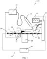
- Fig. 1 shows a first exemplary embodiment of a high-frequency surgery system according to the invention in a schematic view.
- the high-frequency surgery system is marked in its entirety with the reference number 100.
- the high-frequency surgery system has an exemplary embodiment of a monitoring unit 10 according to the invention.
- the monitoring unit 10 is set up to monitor a patient 12 during operation of a high-frequency surgical device 14.
- the high-frequency surgical device 14 in the present case is an electric scalpel with a monopolar design.
- the high-frequency surgical device 14 has an active electrode 16 and a neutral electrode 18.
- the active electrode 16 is designed to cut and/or coagulate biological tissue of the patient 12 using high-frequency electrical energy or by feeding in a high-frequency alternating current.
- the neutral electrode 18 is designed to derive the high-frequency electrical energy from the biological tissue. In the present case, the neutral electrode 18 is applied adhesively as a surface electrode to a thigh of the patient 12.
- the active electrode 16 and the neutral electrode 18 are electrically coupled to a high-frequency generator 20 via one or more cables.
- the high-frequency generator 20 is set up to convert an electrical current obtained from the network side (e.g. via a 230 V, 16 A; or a 380 V, 32 A connection) electronically (e.g. using frequency converters) into one for the operation of the high-frequency surgical device to convert the necessary high-frequency alternating current.
- the frequency of this cutting current is preferably above 300 kHz and below 5 MHz.
- the neutral electrode 18 can also be attached to other parts of the patient's body 12, or alternatively can be formed by a ground connection of an operating table 22.
- the operating table 22 is designed as a horizontal patient support that stands on a floor via a monolithic base 24.
- the operating table is completely electrically isolated from an environment.
- the current fed from the active electrode 16 into the tissue of the patient 12 flows back via the neutral electrode 18 to the grounded high-frequency generator (as ground in the electrical sense).
- the high-frequency surgery system 100 has an exemplary embodiment of the monitoring unit 10 according to the invention.
- the monitoring unit 10 has measuring electrodes 30. In the present case, only three of the large number of measuring electrodes 30 are marked in simplified form. In the present case, the measuring electrodes 30 are arranged in the immediate periphery of the patient 12. In the present case, the peripheral arrangement of the measuring electrodes 30 is limited to the fact that the measuring electrodes 30 are arranged directly on a support surface 32 of the patient bed 22.
- the measuring electrodes 30 are preferably each electrically insulated from one another. An impedance falling between the measuring electrodes is created by the current flow of the measuring alternating current through the tissue of the patient 12 lying between two measuring electrodes.
- the measuring electrodes 30 are in direct contact with the skin of the patient 12, who is lying on the patient bed 22.
- the monitoring unit 10 has an evaluation and control unit 34.
- the evaluation and control unit 34 is set up to impress a predetermined measuring alternating voltage or a predetermined measuring alternating current into the measuring electrodes 30. Furthermore, the evaluation and control unit 34 is set up to measure an impedance Z (or an imaginary part X and/or real part R) falling between the measuring electrodes 30 or to determine it via current or voltage measurement. Furthermore, the evaluation and control unit 34 is set up to record a time course of the impedance 36 (see Fig.
- the warning signal is displayed on a display 42 or a display which is connected to the evaluation and control unit 34 via one or more cables.
- the display is arranged on an operation terminal 44, via which the patient 12 is ventilated during the operation using a ventilation tube 46.
- a second exemplary embodiment of the high-frequency surgery system 100 is shown with a second exemplary embodiment of the monitoring unit 10.
- the high-frequency surgical device 14 is in Fig. 2 designed as a bipolar design of an electric scalpel.
- active electrode 16 and neutral electrode 18 are arranged, for example, in a kind of tweezers with two legs that are insulated from each other, whereby the active-neutral assignment can be exchanged between the legs during operation.
- the monitoring unit 10 has measuring sensors 48.
- the measuring sensors 48 are arranged in the periphery of the patient 12. In the present case, the measuring sensors 48 are each arranged at a distance from one another over the entire surface 32 of the patient support 22. Furthermore, further measuring sensors are arranged in the ventilation tube 46.
- the measuring sensors 48 are set up to record a parameter that is during the separation and/or coagulation of the biological tissue is caused due to the high frequency energy.
- the evaluation and control unit 34 is set up to generate a warning signal based on the parameter.
- the measuring sensors 48 are temperature sensors, in particular thermoelectric elements, such as. B. Thermo elements.
- the measured parameter is a temperature difference in Kelvin. If a parasitic current flow occurs via another power bridge (see Fig. 1 ), heating can be measured in the form of a differential temperature via the temperature sensors 48. If the temperature difference measured over time exceeds a first threshold value, the warning signal is triggered in the form of a maximum temperature T Max .
- FIG. 4 shows a checkerboard-like arrangement of measuring electrodes 30 shown in black and white.
- the impedance can be measured between two adjacent electrodes, but in principle also between any two positive-negative electrode pairs in the checkerboard arrangement, in which the measuring electrodes 30 have a spatially distributed pattern, respectively form adjacent and preferably electrically insulated surface electrodes.
- FIG. 5 A so-called interdigital structure is shown.
- Fig. 6 shows an exemplary embodiment of measuring electrodes 30, for example in the form of metallic threads, incorporated into a fabric, e.g. B. are woven in.
- the fabric 49 shown can, for example, be made of non-conductive fabric or polyester and have a large number of threads woven and/or intertwined. Some of these threads serve as measuring electrodes 30 in a metallic or electrically conductive version (e.g. based on carbon).
- a seat or lounger cover for the patient support 22 can be made from such a material.
- a (support) mat can also be made from such a fabric.
- a checkerboard pattern arrangement of the electrodes can also be produced.
- Fig. 6 schematic impedance measurements are shown as arrows between the respective measuring electrodes 30.
- the impedances Z 1 to Z 4 are measured indirectly via a current or voltage measurement by the evaluation and control unit 20.
- the impedance Z 4 is not measured directly between two adjacent measuring electrodes 30, but rather a measuring electrode was skipped between the measuring electrodes 30.
- Fig. 7 shows a third exemplary embodiment of the high-frequency surgery system 100 with a third exemplary embodiment of the monitoring unit 10.
- the monitoring unit 10 has magnetic and/or electrical antennas 50 as measuring sensors 48.
- the antennas 50 are set up to detect, as the parameter, electromagnetic signals 52 from the periphery of the patient 12, which are generated by the high-frequency energy during the operation of the high-frequency surgical device 14.
- the evaluation and control unit 34 is set up to calculate a current density distribution in space from the measurement signals by solving a mathematical inverse problem, with the recorded measurement signals being proportional to 1/distance • ⁇ I/ ⁇ t in the case of magnetic antennas 50, in the case of electrical antennas 50 proportional to 1/distance • ⁇ V/ ⁇ t behave.
- the antennas 50 are preferably arranged in an immediate operating environment, for example on the patient support 22 and/or on a ceiling above the operation and/or in corners of the operating room. Six antennas 50 are shown schematically here, of which only one has been marked for reasons of clarity.
- Particularly preferred is also a method for monitoring a patient 12 during operation of a high-frequency surgical device 14, wherein the high-frequency surgical device 14 is designed to separate and/or coagulate biological tissue using high-frequency electrical energy.
- the method has the steps: impressing a predetermined measuring alternating voltage or a predetermined measuring alternating current into measuring electrodes 30, which are arranged in a periphery of the patient 12, and measuring between the measuring electrodes 30 falling impedance, as well as monitoring a time course of the impedance 36 and/or a change in the same over time.
- Also preferred as an alternative solution is a method for monitoring a patient 12 during operation of a high-frequency surgical device 14, wherein the high-frequency surgical device 14 is designed to separate and/or coagulate biological tissue using high-frequency electrical energy.
- the method has the steps: detecting electromagnetic measurement signals from a patient's periphery using magnetic and/or electrical antennas, the electromagnetic measurement signals being generated by the high-frequency energy during operation of the high-frequency surgical device; and calculating a current density distribution in space (or of the patient and its periphery) from the electromagnetic measurement signals by solving a mathematical inverse problem.
- the preferred methods for monitoring a patient 12 during operation of a high-frequency surgical device 14 can be designed in a respective method-specific modification according to the refinements and embodiments disclosed above, without being mentioned in redundant form at this point.
Landscapes
- Health & Medical Sciences (AREA)
- Life Sciences & Earth Sciences (AREA)
- Surgery (AREA)
- Engineering & Computer Science (AREA)
- Veterinary Medicine (AREA)
- Molecular Biology (AREA)
- Physics & Mathematics (AREA)
- Public Health (AREA)
- Biomedical Technology (AREA)
- Heart & Thoracic Surgery (AREA)
- Medical Informatics (AREA)
- General Health & Medical Sciences (AREA)
- Animal Behavior & Ethology (AREA)
- Nuclear Medicine, Radiotherapy & Molecular Imaging (AREA)
- Otolaryngology (AREA)
- Plasma & Fusion (AREA)
- Biophysics (AREA)
- Pathology (AREA)
- Radiology & Medical Imaging (AREA)
- Surgical Instruments (AREA)
Applications Claiming Priority (3)
| Application Number | Priority Date | Filing Date | Title |
|---|---|---|---|
| DE102020003524.8A DE102020003524B4 (de) | 2020-06-12 | 2020-06-12 | Überwachungseinheit und Hochfrequenz-Chirurgiesystem mit einer solchen Überwachungseinheit |
| PCT/EP2021/065506 WO2021250116A1 (fr) | 2020-06-12 | 2021-06-09 | Unité de surveillance et système de chirurgie haute fréquence comprenant une telle unité de surveillance |
| EP21734288.0A EP4164531B1 (fr) | 2020-06-12 | 2021-06-09 | Unité de surveillance et système de chirurgie haute fréquence comprenant une telle unité de surveillance |
Related Parent Applications (1)
| Application Number | Title | Priority Date | Filing Date |
|---|---|---|---|
| EP21734288.0A Division EP4164531B1 (fr) | 2020-06-12 | 2021-06-09 | Unité de surveillance et système de chirurgie haute fréquence comprenant une telle unité de surveillance |
Publications (3)
| Publication Number | Publication Date |
|---|---|
| EP4309571A2 true EP4309571A2 (fr) | 2024-01-24 |
| EP4309571A3 EP4309571A3 (fr) | 2024-03-13 |
| EP4309571B1 EP4309571B1 (fr) | 2024-11-20 |
Family
ID=76601186
Family Applications (2)
| Application Number | Title | Priority Date | Filing Date |
|---|---|---|---|
| EP21734288.0A Active EP4164531B1 (fr) | 2020-06-12 | 2021-06-09 | Unité de surveillance et système de chirurgie haute fréquence comprenant une telle unité de surveillance |
| EP23214347.9A Active EP4309571B1 (fr) | 2020-06-12 | 2021-06-09 | Unité de surveillance et système de chirurgie haute fréquence comprenant une telle unité de surveillance |
Family Applications Before (1)
| Application Number | Title | Priority Date | Filing Date |
|---|---|---|---|
| EP21734288.0A Active EP4164531B1 (fr) | 2020-06-12 | 2021-06-09 | Unité de surveillance et système de chirurgie haute fréquence comprenant une telle unité de surveillance |
Country Status (9)
| Country | Link |
|---|---|
| US (1) | US12672908B2 (fr) |
| EP (2) | EP4164531B1 (fr) |
| KR (1) | KR102884814B1 (fr) |
| CN (1) | CN115916082A (fr) |
| DE (1) | DE102020003524B4 (fr) |
| DK (2) | DK4309571T3 (fr) |
| ES (2) | ES3012783T3 (fr) |
| PL (2) | PL4309571T3 (fr) |
| WO (1) | WO2021250116A1 (fr) |
Families Citing this family (4)
| Publication number | Priority date | Publication date | Assignee | Title |
|---|---|---|---|---|
| DE102020003524B4 (de) | 2020-06-12 | 2023-03-23 | Coco Beteiligungsgesellschaft mbH | Überwachungseinheit und Hochfrequenz-Chirurgiesystem mit einer solchen Überwachungseinheit |
| DE102021203843A1 (de) | 2021-04-19 | 2022-10-20 | Robert Bosch Gesellschaft mit beschränkter Haftung | Elektrochirurgisches Instrument und Teil des elektrochirurgischen Instruments |
| KR102718603B1 (ko) * | 2022-02-22 | 2024-10-16 | 한양대학교 에리카산학협력단 | 전기 수술 장치, 임피던스 측정 장치, 전기 수술 장치의 제어 방법 및 임피던스 측정 방법 |
| CN115192186B (zh) * | 2022-08-10 | 2023-09-15 | 浙江舒友仪器设备股份有限公司 | 一种高频电极自动激活输出系统 |
Citations (5)
| Publication number | Priority date | Publication date | Assignee | Title |
|---|---|---|---|---|
| US20080281309A1 (en) | 2007-05-07 | 2008-11-13 | Tyco Healthcare Group Lp | Capacitive electrosurgical return pad with contact quality monitoring |
| US20090234352A1 (en) | 2008-03-17 | 2009-09-17 | Tyco Healthcare Group Lp | Variable Capacitive Electrode Pad |
| US7837680B2 (en) | 2003-11-21 | 2010-11-23 | Megadyne Medical Products, Inc. | Tuned return electrode with matching inductor |
| US8864756B2 (en) | 2007-10-24 | 2014-10-21 | Celon Ag Medical Instruments | HF-surgery device and method for an HF-surgery device |
| DE102018114482A1 (de) | 2018-06-16 | 2019-12-19 | Olympus Winter & Ibe Gmbh | Elektrochirurgische Vorrichtung |
Family Cites Families (18)
| Publication number | Priority date | Publication date | Assignee | Title |
|---|---|---|---|---|
| DE4232255C1 (de) | 1992-09-25 | 1994-02-17 | Siemens Ag | Neutralelektrode und Verfahren zu deren Wiederverwendung für ein Hochfrequenz-Chirurgiegerät mit Applikationsüberwachungseinrichtung |
| DE4329898A1 (de) * | 1993-09-04 | 1995-04-06 | Marcus Dr Besson | Kabelloses medizinisches Diagnose- und Überwachungsgerät |
| NL1001282C2 (nl) * | 1995-09-26 | 1997-03-28 | A J Van Liebergen Holding B V | Inrichting voor slagvolumebepaling van een menselijk hart. |
| EP1006904A4 (fr) * | 1996-10-30 | 2000-06-14 | Megadyne Med Prod Inc | Electrode electrochirurgicale de retour reutilisable |
| US6332891B1 (en) * | 1999-02-16 | 2001-12-25 | Stryker Corporation | System and method for performing image guided surgery |
| CA2541037A1 (fr) | 2005-03-31 | 2006-09-30 | Sherwood Services Ag | Electrode de retour pour la regulation de la temperature et systeme de surveillance de l'electrode de retour |
| US20070049914A1 (en) | 2005-09-01 | 2007-03-01 | Sherwood Services Ag | Return electrode pad with conductive element grid and method |
| US20070167942A1 (en) * | 2006-01-18 | 2007-07-19 | Sherwood Services Ag | RF return pad current distribution system |
| DE102007020583B4 (de) * | 2006-07-19 | 2012-10-11 | Erbe Elektromedizin Gmbh | Elektrodeneinrichtung mit einerImnpedanz-Messeinrichtung und Verfahren zum Herstellen einer derartigen Elektrodeneinrichtung |
| US20080051777A1 (en) * | 2006-08-28 | 2008-02-28 | Dieter Haemmerich | Radiofrequency ablation device for reducing the incidence of skin burns |
| DE102009013917A1 (de) * | 2008-10-30 | 2010-05-12 | Erbe Elektromedizin Gmbh | Elektrochirurgisches Gerät mit einer Temperaturmesseinrichtung, Verfahren zur Bestimmung einer Temperatur und/oder einer Temperaturänderung an einer Neutralelektrode |
| WO2013139945A1 (fr) | 2012-03-21 | 2013-09-26 | Farin Guenter | Dispositif et procédé destinés à mesurer et réguler des effets thermiques dans le domaine de la chirurgie haute fréquence |
| US9867650B2 (en) * | 2013-12-26 | 2018-01-16 | Megadyne Medical Products, Inc. | Universal self-limiting electrosurgical return electrode |
| US10085791B2 (en) * | 2013-12-26 | 2018-10-02 | Megadyne Medical Products, Inc. | Universal self-limiting electrosurgical return electrode |
| US10111703B2 (en) * | 2014-05-06 | 2018-10-30 | Cosman Instruments, Llc | Electrosurgical generator |
| US10646266B2 (en) * | 2015-11-13 | 2020-05-12 | Covidien Lp | System and method for return electrode monitoring |
| US20200188055A1 (en) * | 2017-10-01 | 2020-06-18 | James Keith Bleiler | Surgical Safety Devices and Methods |
| DE102020003524B4 (de) | 2020-06-12 | 2023-03-23 | Coco Beteiligungsgesellschaft mbH | Überwachungseinheit und Hochfrequenz-Chirurgiesystem mit einer solchen Überwachungseinheit |
-
2020
- 2020-06-12 DE DE102020003524.8A patent/DE102020003524B4/de active Active
-
2021
- 2021-06-09 ES ES23214347T patent/ES3012783T3/es active Active
- 2021-06-09 KR KR1020237000030A patent/KR102884814B1/ko active Active
- 2021-06-09 CN CN202180041994.XA patent/CN115916082A/zh active Pending
- 2021-06-09 EP EP21734288.0A patent/EP4164531B1/fr active Active
- 2021-06-09 DK DK23214347.9T patent/DK4309571T3/da active
- 2021-06-09 PL PL23214347.9T patent/PL4309571T3/pl unknown
- 2021-06-09 DK DK21734288.0T patent/DK4164531T3/da active
- 2021-06-09 EP EP23214347.9A patent/EP4309571B1/fr active Active
- 2021-06-09 US US18/009,613 patent/US12672908B2/en active Active
- 2021-06-09 WO PCT/EP2021/065506 patent/WO2021250116A1/fr not_active Ceased
- 2021-06-09 PL PL21734288.0T patent/PL4164531T3/pl unknown
- 2021-06-09 ES ES21734288T patent/ES2974209T3/es active Active
Patent Citations (5)
| Publication number | Priority date | Publication date | Assignee | Title |
|---|---|---|---|---|
| US7837680B2 (en) | 2003-11-21 | 2010-11-23 | Megadyne Medical Products, Inc. | Tuned return electrode with matching inductor |
| US20080281309A1 (en) | 2007-05-07 | 2008-11-13 | Tyco Healthcare Group Lp | Capacitive electrosurgical return pad with contact quality monitoring |
| US8864756B2 (en) | 2007-10-24 | 2014-10-21 | Celon Ag Medical Instruments | HF-surgery device and method for an HF-surgery device |
| US20090234352A1 (en) | 2008-03-17 | 2009-09-17 | Tyco Healthcare Group Lp | Variable Capacitive Electrode Pad |
| DE102018114482A1 (de) | 2018-06-16 | 2019-12-19 | Olympus Winter & Ibe Gmbh | Elektrochirurgische Vorrichtung |
Non-Patent Citations (3)
| Title |
|---|
| "Frank Natterer: The Mathematics of Computerized Tomography.", SOCIETY FOR INDUSTRIAL AND APPLIED MATHEMATICS, 2001 |
| "Für weitere Informationen wird auf Kramme, Rüdiger", 2016, SPRINGER-VERLAG |
| TSAICHIUCHOU: "Optimal Design of SAW Gas Sensing Device by Using Improved Adaptive Neuro-Fuzzy Inference System.", IEEE ACCESS, vol. 3, 2015, pages 420 - 429, XP011580285, DOI: 10.1109/ACCESS.2015.2427291 |
Also Published As
| Publication number | Publication date |
|---|---|
| EP4164531B1 (fr) | 2023-12-13 |
| US20230218333A1 (en) | 2023-07-13 |
| PL4309571T3 (pl) | 2025-03-31 |
| DK4164531T3 (da) | 2024-03-11 |
| ES3012783T3 (en) | 2025-04-10 |
| US12672908B2 (en) | 2026-07-07 |
| WO2021250116A1 (fr) | 2021-12-16 |
| CN115916082A (zh) | 2023-04-04 |
| PL4164531T3 (pl) | 2024-05-27 |
| KR102884814B1 (ko) | 2025-11-11 |
| EP4164531A1 (fr) | 2023-04-19 |
| DE102020003524A1 (de) | 2021-12-16 |
| DE102020003524B4 (de) | 2023-03-23 |
| EP4309571A3 (fr) | 2024-03-13 |
| KR20230023705A (ko) | 2023-02-17 |
| ES2974209T3 (es) | 2024-06-26 |
| EP4309571B1 (fr) | 2024-11-20 |
| DK4309571T3 (da) | 2025-02-17 |
Similar Documents
| Publication | Publication Date | Title |
|---|---|---|
| EP4164531B1 (fr) | Unité de surveillance et système de chirurgie haute fréquence comprenant une telle unité de surveillance | |
| EP2367493B1 (fr) | Appareil électrochirurgical doté d'un dispositif de mesure de température pour la détermination de la température et/ou d'une modification de la température d'une électrode neutre | |
| DE102007020583B4 (de) | Elektrodeneinrichtung mit einerImnpedanz-Messeinrichtung und Verfahren zum Herstellen einer derartigen Elektrodeneinrichtung | |
| DE69232587T2 (de) | Elektrochirurgische vorrichtung für die laproskopie und ähnliche verfahren | |
| EP0598780B1 (fr) | Generateur de haute frequence utile en chirurgie pour inciser des tissus | |
| EP0390937B1 (fr) | Dispositif pour surveiller l'adhésion des électrodes neutres utilisées en chirurgie à haute fréquence | |
| AU2003232023B8 (en) | Self-limiting electrosurgical return electrode | |
| DE60316052T2 (de) | Elektrochirurgisches Instrument mit Lichtmonitor auf Greifarm | |
| DE102007056974B4 (de) | HF-chirurgische Prüfeinrichtung und Verfahren zum Identifizieren einer am Patienten angelegten HF-Neutralelektrode | |
| DE60026191T2 (de) | Automatische Aktivierung des bipolaren Ausgangssignals eines elektrochirurgischen Generators | |
| EP0998216B1 (fr) | Agencement pour la detection, la caracterisation par diagnostic differentiel et le traitement de tumeurs | |
| DE102014008091A1 (de) | Vorrichtung zur Erfassung von Druckbelastungen und/oder Temperaturdifferenzen für den diabetischen Fuß | |
| Golpaygani et al. | A study on performance and safety tests of electrosurgical equipment | |
| DE102018114482A1 (de) | Elektrochirurgische Vorrichtung | |
| EP2337516B1 (fr) | Générateur électrochirurgical haute fréquence | |
| DE3610393C2 (fr) | ||
| Bifulco et al. | Investigating the role of capacitive coupling between the operating table and the return electrode of an electrosurgery unit in the modification of the current density distribution within the patients’ body | |
| HK40104818A (en) | Monitoring unit and high-frequency surgical system comprising such a monitoring unit | |
| DE102008054351B4 (de) | Elektrochirurgischer HF-Generator | |
| DD241550A1 (de) | Hochfrequenzchirugiegeraet | |
| AT527092A1 (de) | Messvorrichtung zur Messung einer Temperatur an einer medizinischen Elektrode | |
| HK40097185B (en) | Monitoring unit and high-frequency surgery system comprising such a monitoring unit | |
| HK40097185A (en) | Monitoring unit and high-frequency surgery system comprising such a monitoring unit | |
| DE102022111745A1 (de) | Vorrichtungen, systeme und verfahren zur energiebasierten behandlung von synovialgelenken und anderen fluidgefüllten räumen | |
| O'connell | A mains earth leakage tester for use by non-engineering staff |
Legal Events
| Date | Code | Title | Description |
|---|---|---|---|
| PUAI | Public reference made under article 153(3) epc to a published international application that has entered the european phase |
Free format text: ORIGINAL CODE: 0009012 |
|
| STAA | Information on the status of an ep patent application or granted ep patent |
Free format text: STATUS: THE APPLICATION HAS BEEN PUBLISHED |
|
| AC | Divisional application: reference to earlier application |
Ref document number: 4164531 Country of ref document: EP Kind code of ref document: P |
|
| AK | Designated contracting states |
Kind code of ref document: A2 Designated state(s): AL AT BE BG CH CY CZ DE DK EE ES FI FR GB GR HR HU IE IS IT LI LT LU LV MC MK MT NL NO PL PT RO RS SE SI SK SM TR |
|
| REG | Reference to a national code |
Ref country code: DE Ref legal event code: R079 Free format text: PREVIOUS MAIN CLASS: A61B0005000000 Ipc: A61B0018120000 Ref country code: DE Ref legal event code: R079 Ref document number: 502021005911 Country of ref document: DE Free format text: PREVIOUS MAIN CLASS: A61B0005000000 Ipc: A61B0018120000 |
|
| PUAL | Search report despatched |
Free format text: ORIGINAL CODE: 0009013 |
|
| STAA | Information on the status of an ep patent application or granted ep patent |
Free format text: STATUS: REQUEST FOR EXAMINATION WAS MADE |
|
| AK | Designated contracting states |
Kind code of ref document: A3 Designated state(s): AL AT BE BG CH CY CZ DE DK EE ES FI FR GB GR HR HU IE IS IT LI LT LU LV MC MK MT NL NO PL PT RO RS SE SI SK SM TR |
|
| RIC1 | Information provided on ipc code assigned before grant |
Ipc: A61B 5/00 20060101ALI20240208BHEP Ipc: A61B 5/24 20210101ALI20240208BHEP Ipc: A61B 5/053 20210101ALI20240208BHEP Ipc: A61B 18/16 20060101ALI20240208BHEP Ipc: A61B 18/14 20060101ALI20240208BHEP Ipc: A61B 18/12 20060101AFI20240208BHEP |
|
| 17P | Request for examination filed |
Effective date: 20240220 |
|
| RBV | Designated contracting states (corrected) |
Designated state(s): AL AT BE BG CH CY CZ DE DK EE ES FI FR GB GR HR HU IE IS IT LI LT LU LV MC MK MT NL NO PL PT RO RS SE SI SK SM TR |
|
| GRAP | Despatch of communication of intention to grant a patent |
Free format text: ORIGINAL CODE: EPIDOSNIGR1 |
|
| STAA | Information on the status of an ep patent application or granted ep patent |
Free format text: STATUS: GRANT OF PATENT IS INTENDED |
|
| RIC1 | Information provided on ipc code assigned before grant |
Ipc: A61B 5/00 20060101ALI20240621BHEP Ipc: A61B 5/24 20210101ALI20240621BHEP Ipc: A61B 5/053 20210101ALI20240621BHEP Ipc: A61B 18/16 20060101ALI20240621BHEP Ipc: A61B 18/14 20060101ALI20240621BHEP Ipc: A61B 18/12 20060101AFI20240621BHEP |
|
| REG | Reference to a national code |
Ref country code: HK Ref legal event code: DE Ref document number: 40104818 Country of ref document: HK |
|
| INTG | Intention to grant announced |
Effective date: 20240710 |
|
| GRAS | Grant fee paid |
Free format text: ORIGINAL CODE: EPIDOSNIGR3 |
|
| GRAA | (expected) grant |
Free format text: ORIGINAL CODE: 0009210 |
|
| STAA | Information on the status of an ep patent application or granted ep patent |
Free format text: STATUS: THE PATENT HAS BEEN GRANTED |
|
| AC | Divisional application: reference to earlier application |
Ref document number: 4164531 Country of ref document: EP Kind code of ref document: P |
|
| AK | Designated contracting states |
Kind code of ref document: B1 Designated state(s): AL AT BE BG CH CY CZ DE DK EE ES FI FR GB GR HR HU IE IS IT LI LT LU LV MC MK MT NL NO PL PT RO RS SE SI SK SM TR |
|
| REG | Reference to a national code |
Ref country code: GB Ref legal event code: FG4D Free format text: NOT ENGLISH |
|
| REG | Reference to a national code |
Ref country code: CH Ref legal event code: EP |
|
| REG | Reference to a national code |
Ref country code: DE Ref legal event code: R096 Ref document number: 502021005911 Country of ref document: DE |
|
| REG | Reference to a national code |
Ref country code: IE Ref legal event code: FG4D Free format text: LANGUAGE OF EP DOCUMENT: GERMAN |
|
| REG | Reference to a national code |
Ref country code: DK Ref legal event code: T3 Effective date: 20250211 |
|
| REG | Reference to a national code |
Ref country code: SE Ref legal event code: TRGR |
|
| REG | Reference to a national code |
Ref country code: LT Ref legal event code: MG9D |
|
| REG | Reference to a national code |
Ref country code: NL Ref legal event code: MP Effective date: 20241120 |
|
| REG | Reference to a national code |
Ref country code: ES Ref legal event code: FG2A Ref document number: 3012783 Country of ref document: ES Kind code of ref document: T3 Effective date: 20250410 |
|
| PG25 | Lapsed in a contracting state [announced via postgrant information from national office to epo] |
Ref country code: HR Free format text: LAPSE BECAUSE OF FAILURE TO SUBMIT A TRANSLATION OF THE DESCRIPTION OR TO PAY THE FEE WITHIN THE PRESCRIBED TIME-LIMIT Effective date: 20241120 Ref country code: IS Free format text: LAPSE BECAUSE OF FAILURE TO SUBMIT A TRANSLATION OF THE DESCRIPTION OR TO PAY THE FEE WITHIN THE PRESCRIBED TIME-LIMIT Effective date: 20250320 Ref country code: PT Free format text: LAPSE BECAUSE OF FAILURE TO SUBMIT A TRANSLATION OF THE DESCRIPTION OR TO PAY THE FEE WITHIN THE PRESCRIBED TIME-LIMIT Effective date: 20250320 |
|
| PG25 | Lapsed in a contracting state [announced via postgrant information from national office to epo] |
Ref country code: FI Free format text: LAPSE BECAUSE OF FAILURE TO SUBMIT A TRANSLATION OF THE DESCRIPTION OR TO PAY THE FEE WITHIN THE PRESCRIBED TIME-LIMIT Effective date: 20241120 Ref country code: NL Free format text: LAPSE BECAUSE OF FAILURE TO SUBMIT A TRANSLATION OF THE DESCRIPTION OR TO PAY THE FEE WITHIN THE PRESCRIBED TIME-LIMIT Effective date: 20241120 |
|
| PG25 | Lapsed in a contracting state [announced via postgrant information from national office to epo] |
Ref country code: BG Free format text: LAPSE BECAUSE OF FAILURE TO SUBMIT A TRANSLATION OF THE DESCRIPTION OR TO PAY THE FEE WITHIN THE PRESCRIBED TIME-LIMIT Effective date: 20241120 |
|
| PG25 | Lapsed in a contracting state [announced via postgrant information from national office to epo] |
Ref country code: NO Free format text: LAPSE BECAUSE OF FAILURE TO SUBMIT A TRANSLATION OF THE DESCRIPTION OR TO PAY THE FEE WITHIN THE PRESCRIBED TIME-LIMIT Effective date: 20250220 |
|
| PG25 | Lapsed in a contracting state [announced via postgrant information from national office to epo] |
Ref country code: GR Free format text: LAPSE BECAUSE OF FAILURE TO SUBMIT A TRANSLATION OF THE DESCRIPTION OR TO PAY THE FEE WITHIN THE PRESCRIBED TIME-LIMIT Effective date: 20250221 Ref country code: LV Free format text: LAPSE BECAUSE OF FAILURE TO SUBMIT A TRANSLATION OF THE DESCRIPTION OR TO PAY THE FEE WITHIN THE PRESCRIBED TIME-LIMIT Effective date: 20241120 |
|
| PG25 | Lapsed in a contracting state [announced via postgrant information from national office to epo] |
Ref country code: RS Free format text: LAPSE BECAUSE OF FAILURE TO SUBMIT A TRANSLATION OF THE DESCRIPTION OR TO PAY THE FEE WITHIN THE PRESCRIBED TIME-LIMIT Effective date: 20250220 |
|
| PG25 | Lapsed in a contracting state [announced via postgrant information from national office to epo] |
Ref country code: SM Free format text: LAPSE BECAUSE OF FAILURE TO SUBMIT A TRANSLATION OF THE DESCRIPTION OR TO PAY THE FEE WITHIN THE PRESCRIBED TIME-LIMIT Effective date: 20241120 |
|
| PG25 | Lapsed in a contracting state [announced via postgrant information from national office to epo] |
Ref country code: EE Free format text: LAPSE BECAUSE OF FAILURE TO SUBMIT A TRANSLATION OF THE DESCRIPTION OR TO PAY THE FEE WITHIN THE PRESCRIBED TIME-LIMIT Effective date: 20241120 |
|
| PG25 | Lapsed in a contracting state [announced via postgrant information from national office to epo] |
Ref country code: RO Free format text: LAPSE BECAUSE OF FAILURE TO SUBMIT A TRANSLATION OF THE DESCRIPTION OR TO PAY THE FEE WITHIN THE PRESCRIBED TIME-LIMIT Effective date: 20241120 |
|
| PG25 | Lapsed in a contracting state [announced via postgrant information from national office to epo] |
Ref country code: SK Free format text: LAPSE BECAUSE OF FAILURE TO SUBMIT A TRANSLATION OF THE DESCRIPTION OR TO PAY THE FEE WITHIN THE PRESCRIBED TIME-LIMIT Effective date: 20241120 |
|
| PG25 | Lapsed in a contracting state [announced via postgrant information from national office to epo] |
Ref country code: CZ Free format text: LAPSE BECAUSE OF FAILURE TO SUBMIT A TRANSLATION OF THE DESCRIPTION OR TO PAY THE FEE WITHIN THE PRESCRIBED TIME-LIMIT Effective date: 20241120 |
|
| PGFP | Annual fee paid to national office [announced via postgrant information from national office to epo] |
Ref country code: SE Payment date: 20250618 Year of fee payment: 5 |
|
| REG | Reference to a national code |
Ref country code: DE Ref legal event code: R097 Ref document number: 502021005911 Country of ref document: DE |
|
| PLBE | No opposition filed within time limit |
Free format text: ORIGINAL CODE: 0009261 |
|
| STAA | Information on the status of an ep patent application or granted ep patent |
Free format text: STATUS: NO OPPOSITION FILED WITHIN TIME LIMIT |
|
| PGFP | Annual fee paid to national office [announced via postgrant information from national office to epo] |
Ref country code: ES Payment date: 20250718 Year of fee payment: 5 |
|
| PGFP | Annual fee paid to national office [announced via postgrant information from national office to epo] |
Ref country code: DE Payment date: 20250813 Year of fee payment: 5 |
|
| PGFP | Annual fee paid to national office [announced via postgrant information from national office to epo] |
Ref country code: IT Payment date: 20250630 Year of fee payment: 5 |
|
| PGFP | Annual fee paid to national office [announced via postgrant information from national office to epo] |
Ref country code: CH Payment date: 20250701 Year of fee payment: 5 |
|
| 26N | No opposition filed |
Effective date: 20250821 |
|
| REG | Reference to a national code |
Ref country code: DE Ref legal event code: R084 Ref document number: 502021005911 Country of ref document: DE |
|
| PG25 | Lapsed in a contracting state [announced via postgrant information from national office to epo] |
Ref country code: MC Free format text: LAPSE BECAUSE OF FAILURE TO SUBMIT A TRANSLATION OF THE DESCRIPTION OR TO PAY THE FEE WITHIN THE PRESCRIBED TIME-LIMIT Effective date: 20241120 |
|
| PG25 | Lapsed in a contracting state [announced via postgrant information from national office to epo] |
Ref country code: LU Free format text: LAPSE BECAUSE OF NON-PAYMENT OF DUE FEES Effective date: 20250609 |
|
| PG25 | Lapsed in a contracting state [announced via postgrant information from national office to epo] |
Ref country code: IE Free format text: LAPSE BECAUSE OF NON-PAYMENT OF DUE FEES Effective date: 20250609 |
|
| PG25 | Lapsed in a contracting state [announced via postgrant information from national office to epo] |
Ref country code: LT Free format text: LAPSE BECAUSE OF FAILURE TO SUBMIT A TRANSLATION OF THE DESCRIPTION OR TO PAY THE FEE WITHIN THE PRESCRIBED TIME-LIMIT Effective date: 20241120 |
|
| REG | Reference to a national code |
Ref country code: CH Ref legal event code: U11 Free format text: ST27 STATUS EVENT CODE: U-0-0-U10-U11 (AS PROVIDED BY THE NATIONAL OFFICE) Effective date: 20260701 |
|
| PGFP | Annual fee paid to national office [announced via postgrant information from national office to epo] |
Ref country code: GB Payment date: 20260623 Year of fee payment: 6 Ref country code: DK Payment date: 20260622 Year of fee payment: 6 Ref country code: PL Payment date: 20260511 Year of fee payment: 6 |
|
| PGFP | Annual fee paid to national office [announced via postgrant information from national office to epo] |
Ref country code: AT Payment date: 20260618 Year of fee payment: 6 |
|
| PGFP | Annual fee paid to national office [announced via postgrant information from national office to epo] |
Ref country code: BE Payment date: 20260622 Year of fee payment: 6 |
|
| PGFP | Annual fee paid to national office [announced via postgrant information from national office to epo] |
Ref country code: FR Payment date: 20260623 Year of fee payment: 6 |
|
| PG25 | Lapsed in a contracting state [announced via postgrant information from national office to epo] |
Ref country code: CY Free format text: LAPSE BECAUSE OF FAILURE TO SUBMIT A TRANSLATION OF THE DESCRIPTION OR TO PAY THE FEE WITHIN THE PRESCRIBED TIME-LIMIT Effective date: 20241120 |