EP4309794A1 - Broyeur planétaire à billes - Google Patents
Broyeur planétaire à billes Download PDFInfo
- Publication number
- EP4309794A1 EP4309794A1 EP22185879.8A EP22185879A EP4309794A1 EP 4309794 A1 EP4309794 A1 EP 4309794A1 EP 22185879 A EP22185879 A EP 22185879A EP 4309794 A1 EP4309794 A1 EP 4309794A1
- Authority
- EP
- European Patent Office
- Prior art keywords
- ball mill
- clamping
- unit
- planetary ball
- grinding
- Prior art date
- Legal status (The legal status is an assumption and is not a legal conclusion. Google has not performed a legal analysis and makes no representation as to the accuracy of the status listed.)
- Pending
Links
- 239000000463 material Substances 0.000 claims abstract description 14
- 230000000295 complement effect Effects 0.000 claims description 2
- 230000008878 coupling Effects 0.000 description 11
- 238000010168 coupling process Methods 0.000 description 11
- 238000005859 coupling reaction Methods 0.000 description 11
- 230000001965 increasing effect Effects 0.000 description 10
- 238000007789 sealing Methods 0.000 description 9
- 238000000034 method Methods 0.000 description 5
- 230000006835 compression Effects 0.000 description 4
- 238000007906 compression Methods 0.000 description 4
- 241000239290 Araneae Species 0.000 description 3
- 230000000694 effects Effects 0.000 description 3
- 239000012530 fluid Substances 0.000 description 3
- 229910000831 Steel Inorganic materials 0.000 description 2
- 239000000919 ceramic Substances 0.000 description 2
- 238000010276 construction Methods 0.000 description 2
- 238000012806 monitoring device Methods 0.000 description 2
- 229910001220 stainless steel Inorganic materials 0.000 description 2
- 239000010935 stainless steel Substances 0.000 description 2
- 239000010959 steel Substances 0.000 description 2
- 230000001419 dependent effect Effects 0.000 description 1
- 238000011038 discontinuous diafiltration by volume reduction Methods 0.000 description 1
- 210000003746 feather Anatomy 0.000 description 1
- 230000001939 inductive effect Effects 0.000 description 1
- 230000002401 inhibitory effect Effects 0.000 description 1
- 238000003780 insertion Methods 0.000 description 1
- 230000037431 insertion Effects 0.000 description 1
- 239000002245 particle Substances 0.000 description 1
- 238000000926 separation method Methods 0.000 description 1
- 239000011343 solid material Substances 0.000 description 1
Images






Classifications
-
- B—PERFORMING OPERATIONS; TRANSPORTING
- B02—CRUSHING, PULVERISING, OR DISINTEGRATING; PREPARATORY TREATMENT OF GRAIN FOR MILLING
- B02C—CRUSHING, PULVERISING, OR DISINTEGRATING IN GENERAL; MILLING GRAIN
- B02C17/00—Disintegrating by tumbling mills, i.e. mills having a container charged with the material to be disintegrated with or without special disintegrating members such as pebbles or balls
- B02C17/04—Disintegrating by tumbling mills, i.e. mills having a container charged with the material to be disintegrated with or without special disintegrating members such as pebbles or balls with unperforated container
- B02C17/08—Disintegrating by tumbling mills, i.e. mills having a container charged with the material to be disintegrated with or without special disintegrating members such as pebbles or balls with unperforated container with containers performing a planetary movement
-
- B—PERFORMING OPERATIONS; TRANSPORTING
- B02—CRUSHING, PULVERISING, OR DISINTEGRATING; PREPARATORY TREATMENT OF GRAIN FOR MILLING
- B02C—CRUSHING, PULVERISING, OR DISINTEGRATING IN GENERAL; MILLING GRAIN
- B02C17/00—Disintegrating by tumbling mills, i.e. mills having a container charged with the material to be disintegrated with or without special disintegrating members such as pebbles or balls
- B02C17/18—Details
Definitions
- Planetary ball mills are known from the prior art. They are used for shredding or grinding ground material.
- the ground material is placed into a grinding bowl with steel balls.
- the grinding bowl is then moved.
- the balls are moved together with the ground material in the grinding bowl and the ground material is comminuted.
- the movement usually takes place as a combined movement of several rotational movements, for example as a combination of a rotation of the grinding bowl about an axis distant from its central axis and a rotation of the grinding bowl about its own central axis. In this way, a good grinding result can be achieved.
- known planetary ball mills are designed in such a way that a large number of operating steps are necessary for loading the planetary ball mill and are generally supported by hand or can be carried out completely by hand.
- the grinding bowl is usually filled and closed, for example screwed or clamped, before it is inserted into the planetary ball mill and fastened there again. This makes the operation of planetary ball mills error-prone, difficult and of low efficiency.
- Such a planetary ball mill is available, for example DE 202008008473 U1 shown.
- the utility model discloses a planetary ball mill with a receiving device for at least one grinding bowl, which is rotatably arranged by means of a drive, the vertical axis of which is arranged eccentrically to the center axis of the housing, the grinding bowl being able to be fixed on the receiving device by means of a pretensioning device, which can be fixed to a grinding bowl holder connected to the receiving device Spider as an abutment for a spindle that biases the grinding bowl against the receiving device.
- a monitoring device for the spider inserted into the grinding bowl holder is arranged on the grinding bowl holder and the monitoring device is set up in such a way that rotation of the receiving device is excluded when the spider is not inserted.
- the object of the present invention is therefore to provide a safe, simple, robust and efficient planetary ball mill, which in particular facilitates the insertion of the grinding bowls.
- a planetary ball mill according to the invention for grinding material to be ground comprises a drive, a grinding device which is driven by the drive and which has a receiving unit for a grinding bowl, wherein the receiving unit has a base for storing the grinding bowl and is designed with a frame which has an opening for loading the receiving unit with the grinding bowl, the grinding device being designed to move the receiving unit on a predetermined path, a stop being provided on each receiving unit at the upper end of the frame and a clamping unit being provided at the lower end of the frame, the clamping unit forms at least part of the standing surface, which is designed to be movable in the direction of the stop, and wherein the planetary ball mill further has at least one clamping drive which drives the clamping unit.
- a grinding bowl can be placed in the receiving unit and at the same time as the grinding bowl is fastened in the receiving unit, the lid can also be fixed without there being any risk of the ground material getting out of the grinding bowl during operation of the mill. In other words, the lid of the grinding bowl no longer needs to be attached or fixed in advance.
- the tensioning drive is preferably designed with a motor or has one. In this way, the grinding bowl can be automatically clamped in the receiving unit.
- the lid and the grinding bowl are preferably designed to be self-centering, i.e. designed in such a way that when the grinding bowl is fastened in the receiving unit, the lid is automatically aligned with the grinding bowl.
- the planetary ball mill preferably has several grinding devices, each of which is driven by the drive. In this way, the throughput can be increased or several different regrinds and/or repeaters of the same regrind can be ground, for example for statistical purposes. This allows the efficiency of the planetary ball mill to be increased.
- the clamping unit preferably has a spindle and the spindle has a spindle thread. In this way, a simple and secure clamping of the grinding bowl can be achieved.
- the spindle thread is preferably designed as a self-locking thread. In this way, it can be achieved in a simple manner that the grinding bowl remains securely clamped, i.e. securely closed, even under load, without the need for an additional element for fixing, for example a locking screw or a fixing pin, or in the sense of increased security even if the additional fixing element fails.
- the spindle thread can be designed as a trapezoidal thread, in particular as a single-start trapezoidal thread.
- the pitch of the spindle thread is flatter than 15°, in particular flatter than 12° and particularly preferably flatter than 9°. In this way, the inhibiting effect of the spindle thread can be increased, meaning that the grinding bowl can be clamped even more securely.
- the receiving unit preferably has a locking element, in particular a locking pin, by means of which the opening can be blocked.
- a locking element in particular a locking pin
- the clamping unit and the clamping drive are designed to be separate from one another and can be coupled to one another.
- the clamping drive can be removed from the clamping unit and the rotation of the grinding device can be carried out without the clamping drive.
- the drive can be designed in a lighter design, which in turn can reduce construction costs.
- the clamping unit and the clamping drive have positive and in particular complementary contact elements, which can be designed, for example, as a cross bar and groove.
- positive and in particular complementary contact elements can be designed, for example, as a cross bar and groove.
- the clamping unit includes hydraulics that generate the movement of the base.
- This makes it possible, starting from the initial clamping movement of the spindle, which is a combined rotational-vertical movement, to generate a clamping movement of the base, which is exclusively a vertical movement. In this way, it can be prevented that the grinding bowl rotates in the receiving unit during the clamping process, thereby increasing the fatigue strength of the planetary ball mill and it can be prevented that the grinding bowl tilts in the receiving unit during the clamping process.
- only one clamping drive is provided, with which all clamping units can be driven separately.
- the weight of the system can be saved and construction costs and operating costs can be reduced.
- the clamping drive is arranged below a loading position of the receiving unit.
- the loading position can be approached in a simple and safe manner and the clamping process can then be carried out immediately after loading the receiving unit with the grinding bowl or filling it. In this way, the efficiency of the planetary ball mill can be increased.
- the planetary ball mill further comprises a loading unit which is set up to load the receiving unit with a grinding bowl and to remove it from the receiving unit.
- a loading unit which is set up to load the receiving unit with a grinding bowl and to remove it from the receiving unit.
- the planetary ball mill can be loaded safely, robustly and quickly.
- Fig. 1a shows a planetary ball mill 100 in an isometric view from the front.
- the planetary ball mill 100 has a housing 122 with which the planetary ball mill 100 is essentially externally limited.
- the planetary ball mill 100 also has a cover 120 which is attached to the housing 122 and with which the planetary ball mill 100 can be covered at the top.
- the planetary ball mill 100 has at least one grinding device 200.
- the planetary ball mill 100 is shown with four grinding devices 200, where in Fig. 1a only two of the four grinding devices 200 are completely visible.
- the grinding devices 200 are located in the upper region of the planetary ball mill 100.
- the cover 120 is designed to be foldable in such a way that it can be adjusted into a covering position in which the four grinding devices 200 are covered and can be adjusted into an open position in which the four grinding devices 200 are accessible to an operator.
- the planetary ball mill 100 also has a loading unit 290 on, which is arranged in the rear area of the planetary ball mill 100.
- the housing 122 does not cover the loading unit 290, so it is constantly accessible to the operator or a corresponding robot.
- the planetary ball mill 100 also has an operating unit 130 with which the planetary ball mill 100 can be operated.
- the reference number 500 shows the area in which the grinding unit 500 is located.
- the grinding unit 500 includes the at least one grinding device 200 and the drive 110.
- Fig. 1b shows the in Fig. 1a Planetary ball mill 100 shown in an isometric view from behind.
- the housing 122 also has an opening 124 which is arranged at the level of the loading unit 290.
- the planetary ball mill 100 can be loaded via the opening 124, in particular with grinding jars 300 (see Fig. 5b ).
- the loading takes place in particular automatically, for example with robot support.
- the planetary ball mill 100 can be designed without a loading unit 290 and without an opening 124. In this way, a simple planetary ball mill 100 that can be loaded manually from the front is provided.
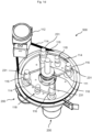
- Fig. 1c shows the grinding unit 500 in the Fig. 1a and 1b Planetary ball mill 100 shown in an isometric view from above.
- the grinding unit 500 is in Fig. 1a marked - there the reference number points and points to a part of the planetary ball mill 100, which is surrounded by the housing 122 (compare Fig. 1a and 1b ).
- the planetary ball mill 100 also has a basic structure 105, a drive 110 and a carrier disk 205.
- the drive 110 has a shaft 111 and a motor 112.
- the shaft 111 is attached to the base frame 105 in a vertical orientation.
- the motor 112 is attached to the base frame 105, which is in Fig. 1c is not shown.
- the carrier disk 205 is attached to the shaft 111 in a horizontal orientation. In this way, the carrier disk 205 can be rotated about a vertical axis which corresponds to the main axis of the shaft 111.
- the drive 110 also has three drive belts 114, wherein in Fig. 1c only one drive belt 114 is marked. This drive belt 114 is connected to the motor 112 and the carrier disk 205 in such a way that the carrier disk 205 can be rotated when the motor 112 is in operation.
- the four grinding devices 200 are arranged on the carrier disk 205 at equal distances from one another and from the shaft 111. In this way, with the rotation of the carrier disk 205, a rotation of the grinding devices 200 is also achieved.
- Fig. 1d shows the in Fig. 1c Grinding unit 500 shown in an isometric view from below.
- the four grinding devices 200 each have a spindle 231, which protrudes downwards from the grinding devices 200.
- the drive 110 also has four pulleys 116, each in the lower area on one of the four grinding devices 200 are attached.
- the drive 110 also has a fifth pulley 116, which is attached to the shaft 111 in the lower region.
- the two drive belts 114 which are in Fig. 1c are not marked, both are arranged below the carrier disk 205 and connected to the shaft 111 via the pulley 116 attached to the shaft 111.
- these two drive belts 114 are each connected to two pulleys 116 attached to a grinding device 200 and a roller 118.
- the two rollers 118 each act as a deflection or tensioning element for the drive belt 114 connected to them.
- the carrier pulley 205 is driven via the drive belt 114 connected to the carrier pulley 205, thereby driving the shaft 111, through which the belt pulley 116 connected to it and thereby in turn the two drive belts 114 arranged below the carrier pulley 205 are driven, which in turn drives the four grinding devices 200.
- a rotation of the grinding devices 200 about the main axis of the shaft 111 and a rotation about the respective main axis of the grinding devices 200 are achieved.
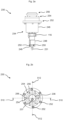
- Fig. 2a shows a clamping unit 230 in a frontal view.
- the clamping unit 230 is each part of a grinding device 200, such as in Fig. 5a and 5c shown.
- the clamping unit 230 has a spindle housing 248 and a plate 249.
- the spindle housing 248 surrounds the spindle 231 in the lower region of the clamping unit 230.
- the clamping unit 230 also has a plurality of springs 250, wherein in Fig. 2a two springs 250 are visible.
- the two springs 250 connect the spindle housing 248 on its underside to the plate 249 on its top.
- the clamping unit 230 also has a hydraulic system 234 with an outer housing 246.
- the pulley 116 is arranged below the outer housing 246.
- Fig. 2b shows the in Fig. 2a Clamping unit 230 shown in a top view.
- the clamping unit 230 also has a closure element 237 for closing the hydraulics 234.
- the clamping unit 230 also has an upper pressure piston 236 in the upper area as part of the hydraulics 234.
- the clamping unit 230 also has screws 252, 254 and threaded holes 256 in the upper area, which are arranged at different levels (see Fig. 2a ) and connect various components of the clamping unit 230 to one another (see Fig. 2d ).
- Fig. 2b is the position of a sectional view 510-510 and perpendicular to this the position of a sectional view 512-512.
- Fig. 2c shows the ones in the Figs. 2a and 2b shown clamping unit 230 in the sectional view 510-510 along the in Fig. 2b horizontally drawn cutting line.
- the spindle 231 points in the middle area there is a shoulder 232 and in the upper area there is a spindle thread 233.
- Below the paragraph 232 there is a bearing 244 which is connected to the inside with the spindle 231 and to the outside with the spindle housing 248. In this way, rotation of the spindle 231 relative to the spindle housing 248 is made possible.
- the clamping unit 230 also has a spindle receptacle 258, which is arranged and designed in such a way that the spindle 231 can be screwed into the spindle receptacle 258 via the spindle thread 233 and the spindle 231 can thereby be retracted vertically upwards into the clamping unit 230.
- the clamping unit 230 Above the spindle 231, the clamping unit 230 has a lower pressure piston 239. Above the lower pressure piston 239, the clamping unit 230 also has a pressure chamber 235, which in turn is limited at the top by the upper pressure piston 236.
- the pressure chamber 235 is designed to hold a hydraulic fluid.
- the clamping unit 230 is designed in such a way that the upper pressure piston 236 is deflected upwards or downwards by a rotation of the spindle 231 relative to the remaining clamping unit 230. This is made possible by the fact that a rotation of the spindle 231 relative to the remaining clamping unit 230 results in the spindle 231 being screwed in or unscrewed into or out of the spindle receptacle 258.
- the functionality is described below only for the screwing-in process of the spindle 231; the unscrewing process occurs in an analogous manner with opposite directions of action.
- Fig. 2d shows the ones in the Fig. 2a to 2c Clamping unit 230 shown in sectional view 512-512 corresponding to in Fig. 2b vertically drawn cutting line.
- the clamping unit 230 also has an outer housing 246 and an inner housing 247.
- the clamping unit 230 is connected to the carrier disk 205 via the outer housing 246 and screwed with the screws 252 (see Fig. 1c ).
- the clamping unit 230 also has a bearing 240 and a further bearing 242, both of which are connected to the outer housing 246 on the outside and to the inner housing 247 on the inside.
- the clamping unit 230 also has a sealing element 260, which is arranged around the upper region of the upper pressure piston 236 and seals the pressure chamber 235 or the hydraulics 234 at the top.
- the sealing element 260 can be designed in several parts, for example from a stripping element arranged at the top with which coarse dirt is wiped off, from a centrally arranged element which represents the actual sealing function and from a guide ring arranged at the bottom with which the upper pressure piston 236 can be inserted into the corresponding recording of the clamping unit 230 is supported.
- the clamping unit 230 also has a further sealing element 262, which is arranged in the upper region of the lower pressure piston 239 and around it and seals the pressure chamber 235 from the inner housing 247.
- the clamping unit 230 also has a lower shaft sealing ring 264, which is arranged in the lower region of the outer housing 246 and seals the bearings 240, 242 downwards.
- the clamping unit 230 also has an upper shaft sealing ring 266, which is arranged in the upper region of the outer housing 246 and seals the bearings 240, 242 at the top.
- the use of shaft seals 264, 266 is particularly advantageous when open bearings 240, 242 are used.
- closed bearings can also be used, which means that the shaft seals 264, 266 can be dispensed with. As a result, the generation of heat due to the rotational friction of the shaft sealing rings 264, 266 on the inner housing 247 can be prevented, whereby material wear can be reduced.
- the clamping unit 230 also has a cross bar 284, which is connected to the spindle 231 in the lower region and is aligned horizontally.
- Fig. 2e shows the ones in the Fig. 2a to 2d
- the clamping unit 230 has a locking pinion 280 below the plate 249.
- the locking pinion 280 is firmly connected to the spindle 231 and arranged above the cross bar 284.
- Fig. 2f shows the ones in the Fig. 2a to 2e clamping unit 230 shown from below.
- the clamping unit 230 also has a locking screw 281, which is screwed into the plate 249 from below and is designed to be brought into contact with the locking pinion 280 in such a way that rotation of the spindle is prevented, ie a locking effect or fixing effect is generated.
- the locking pinion 280 and the locking screw 281 can also be designed differently to create the locking effect, for example the locking screw 281 can be designed as a pin or fixing pin.
- Fig. 3a shows the spindle 231 in an isometric view.
- the spindle 231 has a receptacle 285 in the lower region, which is tapered.
- Fig. 3b shows the in Fig. 3a Spindle 231 shown in a side view.
- the receptacle 285 is continuous.
- the receptacle 285 is designed to accommodate the cross bar 284 (see Fig. 2d ).
- the spindle 231 also has a thread 282 which is arranged perpendicular to the receptacle 285 and perpendicular to the central axis of the spindle 231 and at the level of the receptacle 285.
- a screw for example a grub screw, can be screwed into the thread 282, with which the crossbar 284 can be fixed.
- Fig. 3c shows the in 3a and 3b Spindle 231 shown in another side view.
- Recording 285 (compare 3a and 3b ) is positioned in such a way that the crossbar 284 can be positioned centered in the spindle. This can ensure, particularly with high tightening torques, that the spindle 231 is damaged or that the crossbar 284 bursts out of the receptacle 285 in the lower region of the spindle 231.
- Fig. 4a shows a tension drive 270 in an isometric view.
- the tensioning drive 270 has a lifting device 272 and a coupling unit 286.
- the lifting device 279 is designed to vertically displace the coupling unit 286, that is, to lower and/or raise it.
- the coupling unit 286 is designed to couple the tensioning drive 270 with the tensioning unit 230. The coupling takes place via the coupling unit 286 and the lower region of the spindle 231.
- the clamping drive 270 also has a position plate 277, an upper position sensor 278 and a lower position sensor 279.
- the position plate 277 is designed to be moved vertically to the same extent as the coupling unit 286 and with it, the travel path being limited upwards by the upper position sensor 278 and downwards by the lower position sensor 279.
- the position plate 277 reaches to the upper position sensor 278 or the lower position sensor 279, the clamping drive 270 detects that the upper or lower end position has been reached and ends the vertical movement of the lifting device 272.
- the upper position sensor 278 and the lower position sensor 279 can be designed as non-contact, for example as inductive sensors be.
- the tensioning drive 270 also has a support unit 288, which is designed to when the tensioning unit 230 is coupled to the tensioning drive 270 Plate 249 to be supported on the support unit 288. If the as in the Fig.
- Fig. 4b shows the in Fig. 4a Clamping drive 270 shown in a top view.
- the coupling unit 286 has a groove 287 which is designed to accommodate the cross bar 284 in such a way that a positive connection is made possible.
- Fig. 4b the position of a sectional view 520-520 is also marked.
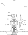
- Fig. 4c shows the one in the 4a and 4b shown clamping drive 270 in the sectional view 520-520 according to the in Fig. 4b horizontally drawn cutting line.
- the tensioning drive 270 also has a linear motor 274, which is arranged within the lifting device 272 and is designed to vertically raise or lower the coupling unit 286.
- the tensioning drive 270 also has a rotation device 289, which is arranged below the coupling unit 286 and is connected to it. If the clamping unit 230 and the clamping drive 270 are coupled to one another via the coupling unit 286, the spindle 231 can be rotated via the rotation device 289.
- Fig. 5a shows a grinding device 200 in an isometric view.
- the grinding device 200 has, in addition to that in the Fig. 2a to 2d shown clamping unit 230 also has a receiving unit 210, which is arranged above the clamping unit 230.
- the recording unit 210 has a frame 214, which is limited at the top with a stop 220.
- the frame 214 has an opening 216 and a locking element 218.
- the locking element 218 is designed to close the opening 216.
- Fig. 5a is the position of a section view 530-530 (cf. Fig. 5c ) and a sectional view 540-540 (cf. Fig. 5d ) marked.
- Fig. 5b shows a grinding bowl 300 in a sectional view.
- the grinding bowl 300 has a lid 310, a lid insert 312, a cup insert 320, a cup housing 330 and a seal 340.
- the cup insert 320 is designed to hold grinding material and is located in the cup housing 330, with which the grinding cup 300 is essentially limited to the outside, that is to say downwards and to the sides.
- the grinding bowl 300 is limited at the top by the lid 310, with the lid insert 312 below the Lid 310 is arranged.
- the grinding bowl 300 is filled from above.
- the seal 340 is arranged around the lid insert 312 and ensures that when the grinding bowl 300 is closed, the material to be ground cannot escape from the grinding bowl 300, especially if it already has very small particles.
- the cup insert 320 and the lid insert 312 are preferably made of ceramic. In this way, high wear resistance can be achieved, especially with abrasive ground material.
- the cup housing 330 and the lid 310 are preferably made of a robust and damage-tolerant material, for example steel or stainless steel, in particular high-strength stainless steel. In this way, reliable protection of the cup insert 320 and the lid insert 312 can be achieved, especially if both are made of brittle ceramic.
- the grinding bowl 300 or its components are designed to be rotationally symmetrical, particularly preferably in such a way that a cylindrical grinding bowl 300 results.
- the components of the grinding bowl are preferably made from solid material. In this way, a high load capacity and fatigue strength of the grinding bowl 300 can be achieved.
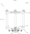
- Fig. 5c shows the in Fig. 5a Grinding device 200 shown with the in Fig. 5b shown grinding bowl 300 in the sectional view 530-530 according to the in Fig. 5a marked cutting line.
- the grinding bowl 300 is located in the receiving unit 210.
- the bottom of the bowl housing 330 rests on the base 212.
- the recording unit 210 also has a base holder 213 which has a recess 211.
- the standing surface receptacle 213 is designed to accommodate the standing surface 212 in the recess 211, the standing surface 213 being able to be guided vertically in the recess 211 and thus vertically movable in the frame 214.
- the standing surface receptacle 213 delimits the frame 214 downwards and is arranged below the standing surface 212.
- the base holder 213 is screwed to the clamping unit 230 via the threaded holes 256, whereby the mobility of the base 212 is limited downwards (cf. Figs. 2a and 2b ).
- the receiving unit 210 also has guide elements 215, which are connected to the standing surface 212 and the standing surface receptacle 213.
- the guide elements 215 are designed to enable or support a vertical relative movement between the standing surface 212 and the standing surface receptacle 213, the maximum vertical distance between the standing surface 212 and the standing surface receptacle 213 being limited by the guide elements 215.
- the upper pressure piston 236 is located directly below the standing surface 212.
- the cover 310 rests against the stop 220 below. If the spindle 231 is moved upwards and the upper pressure piston 236 is deflected upwards - as in connection with Fig. 2c described - the standing surface 212 is deflected upwards, ie according to the position created by the frame 214 in combination with the inserted grinding bowl 300 and the Guide elements 215 predetermined vertical range of movement, whereby the grinding bowl 300 is also deflected upwards and is pressed against the stop 220. This ensures that the lid 310 is pressed onto the cup housing 330, which in turn ensures a secure closure of the grinding cup 300.
- the grinding bowl 300 is fixed in the receiving unit 210 in such a way that it cannot exit the receiving unit 210 (in particular not during the grinding operation) without the clamping state being released again beforehand - by moving the spindle 231 downwards.
- the load exerted in this way on the grinding bowl 300 takes place - in accordance with the deflection of the base 212 - in the vertical direction, with the friction force between the lid 310 and the stop 220 as well as the bottom of the cup housing 330 and the base 212 resulting from the vertical load also being one Stability against transverse loads is achieved.
- the security of the fixation of the grinding bowl 300 can be increased by further moving the spindle 231, thereby increasing the vertical clamping force.
- the frame 214 or the receiving unit 210 is/are adapted to the grinding bowl 300 to be accommodated in such a way that when the grinding bowl 300 is inserted into the receiving unit 210 there is only a small amount of play.
- the adjustment of the frame 214 or the receiving unit 210 takes place in particular according to the height and diameter of the usually cylindrical grinding bowl 300 (see above, corresponding description). Fig. 5b ). Accordingly, in order to fix the grinding bowl 300, only a small vertical offset of the base 212 is necessary and thus ultimately only a small offset of the spindle 231. On the one hand, this can reduce the set-up time, which can increase machine efficiency.
- the safety of the planetary ball mill 100 can also be increased in that, in the event of a possible transverse load on the grinding bowl 300, a small deflection of the standing surface 212 leads to a small lever travel and thus ultimately to a small (transverse) load, in particular on the clamping unit 230 and the receiving unit 210
- an advantageous maximum deflection of the standing surface 212 is 30 mm, in particular 20 mm, particularly preferably 15 mm.
- the guide elements 215 are distributed radially around the central vertical axis of the clamping unit 200. This enables uniform and safe vertical guidance of the standing surface 212.
- the guide elements 215 can, for example, be formed from a screw and a nut, with the nut being screwed onto the screw, resulting in the maximum vertical distance between the standing surface 212 and the standing surface receptacle 213, ie as a free path between the screw head and the nut minus the local material thicknesses of the standing surface 212 and the standing surface receptacle 213.
- the guide elements 215 can each have a compression spring positioned along the screw thread and below the base receptacle 213, which ensures that the base 212 is pulled into the recess 211 . These compression springs can also ensure that the upper pressure piston 236 is also moved back into its starting position, ie downwards.
- Fig. 5d shows the recording unit 210 in the sectional view 540-540 according to the in Fig. 5a marked cutting line.
- the receiving unit 210 also has a positioning element 219, which is connected to the locking element 218, for example screwed, and is designed in such a way that this enables the locking element 218 to be deflected vertically downwards when it is loaded from above.
- the dimensioning of the positioning element 219 also results in the maximum vertical deflection of the locking element 218 upwards, ie the closed position, and the maximum vertical deflection of the locking element 218 downwards, ie the open position.
- the positioning element 219 also has a compression spring 217 which presses the locking element 218 upwards.
- the recording unit 210 is always in the closed position without loading the locking element 218.
- the locking element 218 and the positioning element 219 can also be designed such that the locking element 218 is always in the open position without load or that the locking element 218 can be connected between the closed position and the open position.
Landscapes
- Engineering & Computer Science (AREA)
- Food Science & Technology (AREA)
- Crushing And Grinding (AREA)
Priority Applications (1)
| Application Number | Priority Date | Filing Date | Title |
|---|---|---|---|
| EP22185879.8A EP4309794A1 (fr) | 2022-07-19 | 2022-07-19 | Broyeur planétaire à billes |
Applications Claiming Priority (1)
| Application Number | Priority Date | Filing Date | Title |
|---|---|---|---|
| EP22185879.8A EP4309794A1 (fr) | 2022-07-19 | 2022-07-19 | Broyeur planétaire à billes |
Publications (2)
| Publication Number | Publication Date |
|---|---|
| EP4309794A1 true EP4309794A1 (fr) | 2024-01-24 |
| EP4309794A8 EP4309794A8 (fr) | 2024-03-06 |
Family
ID=82656848
Family Applications (1)
| Application Number | Title | Priority Date | Filing Date |
|---|---|---|---|
| EP22185879.8A Pending EP4309794A1 (fr) | 2022-07-19 | 2022-07-19 | Broyeur planétaire à billes |
Country Status (1)
| Country | Link |
|---|---|
| EP (1) | EP4309794A1 (fr) |
Citations (2)
| Publication number | Priority date | Publication date | Assignee | Title |
|---|---|---|---|---|
| DE202008008473U1 (de) | 2008-06-26 | 2008-08-28 | Retsch Gmbh | Sicherheitsvorrichtung für Fliehkraftmühlen mit ungesicherten Mahlbechern |
| DE102012009987A1 (de) * | 2012-05-22 | 2013-11-28 | Fritsch Gmbh | Laborkugelmühle |
-
2022
- 2022-07-19 EP EP22185879.8A patent/EP4309794A1/fr active Pending
Patent Citations (2)
| Publication number | Priority date | Publication date | Assignee | Title |
|---|---|---|---|---|
| DE202008008473U1 (de) | 2008-06-26 | 2008-08-28 | Retsch Gmbh | Sicherheitsvorrichtung für Fliehkraftmühlen mit ungesicherten Mahlbechern |
| DE102012009987A1 (de) * | 2012-05-22 | 2013-11-28 | Fritsch Gmbh | Laborkugelmühle |
Also Published As
| Publication number | Publication date |
|---|---|
| EP4309794A8 (fr) | 2024-03-06 |
Similar Documents
| Publication | Publication Date | Title |
|---|---|---|
| DE102012009987B4 (de) | Laborkugelmühle | |
| EP3597300B1 (fr) | Paquet de rouleaux pour dispositifs de broyage, dispositifs de broyage et procédé | |
| DE102019126162B4 (de) | Kugelmühle | |
| EP4251894B1 (fr) | Procédé de changement d'un coussinet de palier lisse disposé sur un arbre de rotor d'un palier de rotor d'une éolienne | |
| DE1252044B (fr) | ||
| DE2846630A1 (de) | Vorrichtung zum anheben des bodens von kannen | |
| DE3212700A1 (de) | Apparat zum trennen eines agglomerierten partikulierten materials | |
| DE2164659A1 (de) | Drehbrecher | |
| EP3129148B1 (fr) | Fixation de l'axe dans un concasseur à cône | |
| CH671527A5 (fr) | ||
| DE2112651B2 (de) | Spann- und Lösevorrichtung fur Werkzeuge an Bohr-, Fräs- u.dgl. Werkzeugmaschinen | |
| EP4309794A1 (fr) | Broyeur planétaire à billes | |
| DE2841952A1 (de) | Presse wie schmiedepresse o.dgl. | |
| DE3912324A1 (de) | Verschliesskopf | |
| DE69503266T2 (de) | Verfahren und Vorrichtung zur Aufbereitung von Sand | |
| DE2056429A1 (de) | Ortsbewegliche Vorrichtung zum Untergreifen und anschließenden Heben von Lasten | |
| EP0603589A2 (fr) | Fourchette de rouleau pour rouleau de groupe imprimant de machine à imprimer | |
| EP3727697B1 (fr) | Module de levier de cylindre | |
| DE1055924B (de) | Kreiselbrecher | |
| DE2303325A1 (de) | Zweiwalzen-schraegwalzwerk mit uebereinanderliegenden schraegwalzen und seitlichen fuehrungselementen | |
| EP0221079A1 (fr) | Broyeur a pilon | |
| DE1202456B (de) | Einrichtung zum Ein- und Nachstellen des Flankenspiels in einer Schraubenwinde | |
| DE1752545A1 (de) | Rotierender Werkstuecktraeger fuer Werkzeugmaschinen | |
| DE19721072A1 (de) | Tragbare Elektropreßvorrichtung | |
| DE3100854C2 (fr) |
Legal Events
| Date | Code | Title | Description |
|---|---|---|---|
| PUAI | Public reference made under article 153(3) epc to a published international application that has entered the european phase |
Free format text: ORIGINAL CODE: 0009012 |
|
| STAA | Information on the status of an ep patent application or granted ep patent |
Free format text: STATUS: THE APPLICATION HAS BEEN PUBLISHED |
|
| AK | Designated contracting states |
Kind code of ref document: A1 Designated state(s): AL AT BE BG CH CY CZ DE DK EE ES FI FR GB GR HR HU IE IS IT LI LT LU LV MC MK MT NL NO PL PT RO RS SE SI SK SM TR |
|
| RIN1 | Information on inventor provided before grant (corrected) |
Inventor name: HERZOG, JAN Inventor name: FIEGE, THOMAS Inventor name: HOFFMANN, MATHIAS |
|
| STAA | Information on the status of an ep patent application or granted ep patent |
Free format text: STATUS: REQUEST FOR EXAMINATION WAS MADE |
|
| 17P | Request for examination filed |
Effective date: 20240722 |
|
| RBV | Designated contracting states (corrected) |
Designated state(s): AL AT BE BG CH CY CZ DE DK EE ES FI FR GB GR HR HU IE IS IT LI LT LU LV MC MK MT NL NO PL PT RO RS SE SI SK SM TR |