EP4309901A1 - Tête d'impression à jet d'encre avec système d'élimination de brouillard - Google Patents
Tête d'impression à jet d'encre avec système d'élimination de brouillard Download PDFInfo
- Publication number
- EP4309901A1 EP4309901A1 EP22186161.0A EP22186161A EP4309901A1 EP 4309901 A1 EP4309901 A1 EP 4309901A1 EP 22186161 A EP22186161 A EP 22186161A EP 4309901 A1 EP4309901 A1 EP 4309901A1
- Authority
- EP
- European Patent Office
- Prior art keywords
- print head
- electrodes
- air duct
- air
- array
- Prior art date
- Legal status (The legal status is an assumption and is not a legal conclusion. Google has not performed a legal analysis and makes no representation as to the accuracy of the status listed.)
- Withdrawn
Links
Images
Classifications
-
- B—PERFORMING OPERATIONS; TRANSPORTING
- B41—PRINTING; LINING MACHINES; TYPEWRITERS; STAMPS
- B41J—TYPEWRITERS; SELECTIVE PRINTING MECHANISMS, i.e. MECHANISMS PRINTING OTHERWISE THAN FROM A FORME; CORRECTION OF TYPOGRAPHICAL ERRORS
- B41J2/00—Typewriters or selective printing mechanisms characterised by the printing or marking process for which they are designed
- B41J2/005—Typewriters or selective printing mechanisms characterised by the printing or marking process for which they are designed characterised by bringing liquid or particles selectively into contact with a printing material
- B41J2/01—Ink jet
- B41J2/17—Ink jet characterised by ink handling
- B41J2/1714—Conditioning of the outside of ink supply systems, e.g. inkjet collector cleaning, ink mist removal
-
- B—PERFORMING OPERATIONS; TRANSPORTING
- B41—PRINTING; LINING MACHINES; TYPEWRITERS; STAMPS
- B41J—TYPEWRITERS; SELECTIVE PRINTING MECHANISMS, i.e. MECHANISMS PRINTING OTHERWISE THAN FROM A FORME; CORRECTION OF TYPOGRAPHICAL ERRORS
- B41J29/00—Details of, or accessories for, typewriters or selective printing mechanisms not otherwise provided for
- B41J29/377—Cooling or ventilating arrangements
Definitions
- the invention relates to an ink jet print head having a nozzle face arranged to form a gap with a surface of a media conveyor, an air duct and a suction blower arranged to withdraw air from said gap, and an array of electrodes arranged to create an inhomogeneous electric field for attracting droplets of an ink mist.
- a print head of this type has been disclosed in US 2008225080 A1 .
- the air duct and the blower are provided for removing a mist of liquid ink that is formed in the gap when ink droplets impinge on the surface of the media.
- the air duct contains a filter for separating the mist droplets from the air in order to prevent air pollution in the environment of the printer.
- the printer has a curing lamp that is facing the surface of the media conveyor and is disposed immediately downstream of the nozzle face.
- the electrodes are arranged on opposite sides of the curing lamp in order to attract ink droplets that would otherwise contaminate the curing lamp.
- a print head according to the invention is characterized by the feature that said array of electrodes is arranged within the air duct.
- the electrodes have the function to separate the mist droplets from the air that is withdrawn through the air duct.
- a filter for removing residual mist may still be provided in the air duct downstream of the array of electrodes, but since a major part of the mist droplets has already been removed by means of the electrodes, the rate at which the filter becomes clogged is reduced significantly, so that the maintenance intervals can be extended.
- the liquid ink that has been attracted to the electrodes can easily be removed from time to time, e.g. by means of a wiper, so that the maintenance of the mist removing system is facilitated.
- the array of electrodes may be an alternating array of positive and negative electrodes that are embedded in an electrically insulating electrode plate at least one surface of which is exposed to the current of air and mist in the air duct.
- At least two electrode plates are arranged opposite to one another to delimit a flow path for the air and mist.
- the electrode plates may be arranged to form a labyrinth.
- the electrode plates may form two interleaved comb-like structures that project from opposite walls of the air duct, forcing the air to flow through the duct in a meandering flow pattern.
- the walls of the air duct that carry the comb-like structures of electrode plates are preferably detachable from the rest of the air duct, so that the electrode plates can easily be accessed for cleaning purposes.
- the air duct may have an inlet for ambient air formed downstream of the gap but upstream of the electrode plates, so that the mist-loaded air that is withdrawn from the gap is diluted with ambient air before passing the electrode plates.
- the ambient air inlet may also be utilized for controlling the volume of air that is withdrawn from the gap and, therewith, the flow velocity of the air within the gap.
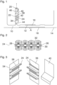
- a print head 10 has a nozzle face 12 arranged above a surface of a media conveyor 14, so that a gap 16 is formed between the nozzle face and the media conveyor.
- the media conveyor 14 may for example be formed by an endless belt and serves for moving media sheets 18 past the nozzle face 12 in a direction designated by an arrow A, so that an image may be printed onto the media sheet by ejecting ink droplets from nozzles formed in the nozzle face 12.
- the nozzle face 12 may be a surface of a chip that integrates a large number of piezoelectric ink ejection units.
- a suction blower 20 and an air duct 22 are provided inside the print head 10 and arranged to withdraw air from the gap 16 near the downstream end of the gap.
- the air duct 22 branches off from the gap 16 at right angles. It will be understood that the air duct 22 will extend over the entire width of the nozzle face 16 in the direction normal to the plane of the drawing in Fig. 1 .
- the flow rate of the air in the air duct 22 may be controlled such that the flow of air that is created in the gap 16 by the movement of the media conveyor and the media is almost totally diverted into the air duct 22 so that practically no air current on even a countercurrent of air is present in the end of the duct 16 located beyond of the air duct 22 on the left side in Fig. 1 .
- the flow rate in the air duct 22 will not significantly increase the air current that is flowing past the nozzle face 12, so that the air current along the nozzle face is not significantly larger than the current that would be induced by the movement of the media conveyor and the media, anyway. Consequently, the flow velocity of the air is so small that it will not cause substantial aberration of the ink droplets that are jetted out from the nozzles.
- the air duct 22 contains a labyrinth that is at least partly formed by electrode plates 24.
- each electrode plate 24 is constituted by an electrically insulating plate 26 into which an array of alternating positive electrodes 28 and negative electrodes 30 has been embedded.
- the electrodes 28, 30 extend in parallel, e.g. in a direction transverse to the flow direction of air in the air duct 22.
- a voltage difference of, e.g., 350 V exists between the positive and negative electrodes, so that the electrodes generate an inhomogeneous electric field 32, as has been shown symbolically in Fig. 2 .
- mist droplets carried along in the air current in the air duct 22 have a negative charge, they will be attracted by the positive electrodes 28, and if they have a positive charge, they will be attracted by the negative electrodes 30. If the droplets do not carry an electric charge, they will nevertheless be attracted to one of the electrodes because of the inhomogeneity of the electric field 32.
- the electrode plates 24 are mounted onto parallel vertical plates 34, 36 which constitute side walls of the air duct 22.
- every second electrode plate 24 is formed along the edge of a ledge 38 whereas the other half of the electrode plates is attached directly to the vertical plate 34 and 36, respectively.
- the electrode plates 24 and ledges 38 form two interleaved comb-like structures forming the labyrinth through which the air current is forced to flow in a meandering flow pattern. This increases the likelihood that almost all ink droplets will be attracted to and collected at one of the electrode plates 24.
- the vertical plate 36 and another essentially vertical plate 40 delimit an intake duct 42 ( Fig. 1 ) for ambient air that opens out into the air duct 22 in a position below (upstream of) the labyrinth of electrode plates 24.
- the lower end of the plate 40 is angled towards the plate 34, so that both plates together form a throttle 44 limiting the flow of air from the gap 16 into the air duct 22. This has the effect that an underpressure is created above (downstream of) the throttle 44, so that ambient air is drawn in through the intake duct 42. In this way, the flow velocity of the air in the air duct 22 can be increased without withdrawing too much air from the gap 16.
- the increased flow velocity may cause a turbulent flow of air in the labyrinths, so that the mist droplets can be collected by the electrode plates 24 more efficiently.
- the air drawn in through the intake duct 42 permits to operate the blower 20 at a higher speed, so that the amount of air withdrawn from the gap 16 via the throttle 44 can be controlled more precisely.
- a filter 46 is provided in the air duct 22 between the labyrinth of the electrode plates 24 and the suction blower 20.
- the purpose of this filter 46 is to hold back any residual mist droplets that may have escaped the electrode plates 24. Since the amount of ink that remains to be filtered-out in the filter 46 is only very small, the filter can operate for a large operation time without having to be regenerated. This reduces maintenance work as well as costs for the filter material.
- the vertical plates 34, 36 and 40 are detachably mounted in the print head 10. When these plates have been detached, the electrode plates 24 are easily accessible, as is shown in Fig. 3 , and the ink collected at the electrode plates 24 can easily be wiped-off with a wiper. In this way, the maintenance work required for the mist removing system is facilitated.
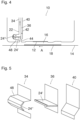
- Figs. 4 and 5 illustrate a modified embodiment which differs from the embodiment shown in Figs. 1 to 3 in that an electrode plate 24' is configured as a baffle that projects from the vertical wall 36 into a depression 48 formed in the opposite wall 34. Another electrode plate 24" forms a lining in the bottom of the depression 48. Again, the electrode plates 24' and 24" constitute a labyrinth for effectively collecting the mist entering through the throttle 44.
Landscapes
- Ink Jet (AREA)
- Particle Formation And Scattering Control In Inkjet Printers (AREA)
Priority Applications (4)
| Application Number | Priority Date | Filing Date | Title |
|---|---|---|---|
| EP22186161.0A EP4309901A1 (fr) | 2022-07-21 | 2022-07-21 | Tête d'impression à jet d'encre avec système d'élimination de brouillard |
| PCT/EP2023/069331 WO2024017736A1 (fr) | 2022-07-21 | 2023-07-12 | Tête d'impression à jet d'encre avec système d'élimination de brouillard |
| EP23741392.7A EP4558337A1 (fr) | 2022-07-21 | 2023-07-12 | Tête d'impression à jet d'encre avec système d'élimination de brouillard |
| US19/013,751 US20250144938A1 (en) | 2022-07-21 | 2025-01-08 | Ink jet print head with mist removing system |
Applications Claiming Priority (1)
| Application Number | Priority Date | Filing Date | Title |
|---|---|---|---|
| EP22186161.0A EP4309901A1 (fr) | 2022-07-21 | 2022-07-21 | Tête d'impression à jet d'encre avec système d'élimination de brouillard |
Publications (1)
| Publication Number | Publication Date |
|---|---|
| EP4309901A1 true EP4309901A1 (fr) | 2024-01-24 |
Family
ID=82656726
Family Applications (2)
| Application Number | Title | Priority Date | Filing Date |
|---|---|---|---|
| EP22186161.0A Withdrawn EP4309901A1 (fr) | 2022-07-21 | 2022-07-21 | Tête d'impression à jet d'encre avec système d'élimination de brouillard |
| EP23741392.7A Pending EP4558337A1 (fr) | 2022-07-21 | 2023-07-12 | Tête d'impression à jet d'encre avec système d'élimination de brouillard |
Family Applications After (1)
| Application Number | Title | Priority Date | Filing Date |
|---|---|---|---|
| EP23741392.7A Pending EP4558337A1 (fr) | 2022-07-21 | 2023-07-12 | Tête d'impression à jet d'encre avec système d'élimination de brouillard |
Country Status (3)
| Country | Link |
|---|---|
| US (1) | US20250144938A1 (fr) |
| EP (2) | EP4309901A1 (fr) |
| WO (1) | WO2024017736A1 (fr) |
Citations (4)
| Publication number | Priority date | Publication date | Assignee | Title |
|---|---|---|---|---|
| JP2002211005A (ja) * | 2001-01-12 | 2002-07-31 | Canon Inc | インクジェット記録装置 |
| US20040061738A1 (en) * | 2002-09-26 | 2004-04-01 | Yasuhiro Unosawa | Ink jet recording apparatus |
| US20070229611A1 (en) * | 2006-03-29 | 2007-10-04 | Fujifilm Corporation | Liquid ejection head and image forming apparatus comprising same |
| US20080225080A1 (en) | 2007-03-14 | 2008-09-18 | Katsuyuki Hirato | Ink-jet recording apparatus |
-
2022
- 2022-07-21 EP EP22186161.0A patent/EP4309901A1/fr not_active Withdrawn
-
2023
- 2023-07-12 EP EP23741392.7A patent/EP4558337A1/fr active Pending
- 2023-07-12 WO PCT/EP2023/069331 patent/WO2024017736A1/fr not_active Ceased
-
2025
- 2025-01-08 US US19/013,751 patent/US20250144938A1/en active Pending
Patent Citations (4)
| Publication number | Priority date | Publication date | Assignee | Title |
|---|---|---|---|---|
| JP2002211005A (ja) * | 2001-01-12 | 2002-07-31 | Canon Inc | インクジェット記録装置 |
| US20040061738A1 (en) * | 2002-09-26 | 2004-04-01 | Yasuhiro Unosawa | Ink jet recording apparatus |
| US20070229611A1 (en) * | 2006-03-29 | 2007-10-04 | Fujifilm Corporation | Liquid ejection head and image forming apparatus comprising same |
| US20080225080A1 (en) | 2007-03-14 | 2008-09-18 | Katsuyuki Hirato | Ink-jet recording apparatus |
Also Published As
| Publication number | Publication date |
|---|---|
| EP4558337A1 (fr) | 2025-05-28 |
| WO2024017736A1 (fr) | 2024-01-25 |
| US20250144938A1 (en) | 2025-05-08 |
Similar Documents
| Publication | Publication Date | Title |
|---|---|---|
| JP6632190B2 (ja) | 液体吐出装置および液体吐出方法 | |
| CN101152804B (zh) | 片材输送装置 | |
| US8506072B2 (en) | Printing apparatus | |
| US7682002B2 (en) | Printer having improved gas flow drop deflection | |
| JPH0624872B2 (ja) | インクジェットプリンタ | |
| EP0060399B1 (fr) | Imprimante à jet d'encre | |
| CA1143781A (fr) | Conduit de circulation d'air pour reduire la resistance exercee sur le jet d'encre d'un imprimante | |
| US20080111851A1 (en) | Printing Mechanism with Ink Spray Suction | |
| JP2008213477A (ja) | インク式印刷機内印刷用媒体エスコートベルト | |
| JP2007261204A (ja) | 液体吐出ヘッド及びこれを備えた画像形成装置 | |
| JP2006315226A (ja) | 液滴吐出装置 | |
| JP2006069739A (ja) | 記録装置 | |
| US20250144938A1 (en) | Ink jet print head with mist removing system | |
| JP6214208B2 (ja) | 画像形成装置 | |
| JP2010131917A (ja) | インクジェット記録装置 | |
| US9050836B2 (en) | Printer with transfer belt and sheet pressing roller | |
| CN111204130B (zh) | 喷墨打印装置 | |
| US8382258B2 (en) | Moving liquid curtain catcher | |
| JP2016124152A (ja) | インクジェット記録装置 | |
| JP2004330599A (ja) | インクジェット記録装置 | |
| JP6236984B2 (ja) | 液滴吐出装置 | |
| US8398222B2 (en) | Printing using liquid film solid catcher surface | |
| US8444260B2 (en) | Liquid film moving over solid catcher surface | |
| JP7233897B2 (ja) | インクジェット記録装置 | |
| JP4946885B2 (ja) | 印刷装置 |
Legal Events
| Date | Code | Title | Description |
|---|---|---|---|
| PUAI | Public reference made under article 153(3) epc to a published international application that has entered the european phase |
Free format text: ORIGINAL CODE: 0009012 |
|
| STAA | Information on the status of an ep patent application or granted ep patent |
Free format text: STATUS: THE APPLICATION HAS BEEN PUBLISHED |
|
| AK | Designated contracting states |
Kind code of ref document: A1 Designated state(s): AL AT BE BG CH CY CZ DE DK EE ES FI FR GB GR HR HU IE IS IT LI LT LU LV MC MK MT NL NO PL PT RO RS SE SI SK SM TR |
|
| STAA | Information on the status of an ep patent application or granted ep patent |
Free format text: STATUS: THE APPLICATION IS DEEMED TO BE WITHDRAWN |
|
| 18D | Application deemed to be withdrawn |
Effective date: 20240725 |