EP4310432A1 - Composant de refroidissement et son procédé de fabrication - Google Patents
Composant de refroidissement et son procédé de fabrication Download PDFInfo
- Publication number
- EP4310432A1 EP4310432A1 EP23183576.0A EP23183576A EP4310432A1 EP 4310432 A1 EP4310432 A1 EP 4310432A1 EP 23183576 A EP23183576 A EP 23183576A EP 4310432 A1 EP4310432 A1 EP 4310432A1
- Authority
- EP
- European Patent Office
- Prior art keywords
- heat sink
- connecting part
- cooling component
- medium
- connection
- Prior art date
- Legal status (The legal status is an assumption and is not a legal conclusion. Google has not performed a legal analysis and makes no representation as to the accuracy of the status listed.)
- Granted
Links
Images



Classifications
-
- F—MECHANICAL ENGINEERING; LIGHTING; HEATING; WEAPONS; BLASTING
- F28—HEAT EXCHANGE IN GENERAL
- F28F—DETAILS OF HEAT-EXCHANGE AND HEAT-TRANSFER APPARATUS, OF GENERAL APPLICATION
- F28F9/00—Casings; Header boxes; Auxiliary supports for elements; Auxiliary members within casings
- F28F9/02—Header boxes; End plates
- F28F9/04—Arrangements for sealing elements into header boxes or end plates
- F28F9/06—Arrangements for sealing elements into header boxes or end plates by dismountable joints
-
- F—MECHANICAL ENGINEERING; LIGHTING; HEATING; WEAPONS; BLASTING
- F28—HEAT EXCHANGE IN GENERAL
- F28F—DETAILS OF HEAT-EXCHANGE AND HEAT-TRANSFER APPARATUS, OF GENERAL APPLICATION
- F28F9/00—Casings; Header boxes; Auxiliary supports for elements; Auxiliary members within casings
- F28F9/02—Header boxes; End plates
- F28F9/0219—Arrangements for sealing end plates into casing or header box; Header box sub-elements
- F28F9/0221—Header boxes or end plates formed by stacked elements
-
- H—ELECTRICITY
- H05—ELECTRIC TECHNIQUES NOT OTHERWISE PROVIDED FOR
- H05K—PRINTED CIRCUITS; CASINGS OR CONSTRUCTIONAL DETAILS OF ELECTRIC APPARATUS; MANUFACTURE OF ASSEMBLAGES OF ELECTRICAL COMPONENTS
- H05K7/00—Constructional details common to different types of electric apparatus
- H05K7/20—Modifications to facilitate cooling, ventilating, or heating
- H05K7/20218—Modifications to facilitate cooling, ventilating, or heating using a liquid coolant without phase change in electronic enclosures
- H05K7/20263—Heat dissipaters releasing heat from coolant
-
- F—MECHANICAL ENGINEERING; LIGHTING; HEATING; WEAPONS; BLASTING
- F28—HEAT EXCHANGE IN GENERAL
- F28F—DETAILS OF HEAT-EXCHANGE AND HEAT-TRANSFER APPARATUS, OF GENERAL APPLICATION
- F28F21/00—Constructions of heat-exchange apparatus characterised by the selection of particular materials
- F28F21/06—Constructions of heat-exchange apparatus characterised by the selection of particular materials of plastics material
-
- F—MECHANICAL ENGINEERING; LIGHTING; HEATING; WEAPONS; BLASTING
- F28—HEAT EXCHANGE IN GENERAL
- F28F—DETAILS OF HEAT-EXCHANGE AND HEAT-TRANSFER APPARATUS, OF GENERAL APPLICATION
- F28F21/00—Constructions of heat-exchange apparatus characterised by the selection of particular materials
- F28F21/08—Constructions of heat-exchange apparatus characterised by the selection of particular materials of metal
-
- F—MECHANICAL ENGINEERING; LIGHTING; HEATING; WEAPONS; BLASTING
- F28—HEAT EXCHANGE IN GENERAL
- F28F—DETAILS OF HEAT-EXCHANGE AND HEAT-TRANSFER APPARATUS, OF GENERAL APPLICATION
- F28F3/00—Plate-like or laminated elements; Assemblies of plate-like or laminated elements
- F28F3/12—Elements constructed in the shape of a hollow panel, e.g. with channels
-
- F—MECHANICAL ENGINEERING; LIGHTING; HEATING; WEAPONS; BLASTING
- F28—HEAT EXCHANGE IN GENERAL
- F28F—DETAILS OF HEAT-EXCHANGE AND HEAT-TRANSFER APPARATUS, OF GENERAL APPLICATION
- F28F9/00—Casings; Header boxes; Auxiliary supports for elements; Auxiliary members within casings
- F28F9/02—Header boxes; End plates
- F28F9/026—Header boxes; End plates with static flow control means, e.g. with means for uniformly distributing heat exchange media into conduits
- F28F9/0265—Header boxes; End plates with static flow control means, e.g. with means for uniformly distributing heat exchange media into conduits by using guiding means or impingement means inside the header box
-
- F—MECHANICAL ENGINEERING; LIGHTING; HEATING; WEAPONS; BLASTING
- F28—HEAT EXCHANGE IN GENERAL
- F28F—DETAILS OF HEAT-EXCHANGE AND HEAT-TRANSFER APPARATUS, OF GENERAL APPLICATION
- F28F9/00—Casings; Header boxes; Auxiliary supports for elements; Auxiliary members within casings
- F28F9/26—Arrangements for connecting different sections of heat-exchange elements, e.g. of radiators
-
- H—ELECTRICITY
- H05—ELECTRIC TECHNIQUES NOT OTHERWISE PROVIDED FOR
- H05K—PRINTED CIRCUITS; CASINGS OR CONSTRUCTIONAL DETAILS OF ELECTRIC APPARATUS; MANUFACTURE OF ASSEMBLAGES OF ELECTRICAL COMPONENTS
- H05K7/00—Constructional details common to different types of electric apparatus
- H05K7/20—Modifications to facilitate cooling, ventilating, or heating
- H05K7/20218—Modifications to facilitate cooling, ventilating, or heating using a liquid coolant without phase change in electronic enclosures
- H05K7/20272—Accessories for moving fluid, for expanding fluid, for connecting fluid conduits, for distributing fluid, for removing gas or for preventing leakage, e.g. pumps, tanks or manifolds
-
- H—ELECTRICITY
- H10—SEMICONDUCTOR DEVICES; ELECTRIC SOLID-STATE DEVICES NOT OTHERWISE PROVIDED FOR
- H10W—GENERIC PACKAGES, INTERCONNECTIONS, CONNECTORS OR OTHER CONSTRUCTIONAL DETAILS OF DEVICES COVERED BY CLASS H10
- H10W40/00—Arrangements for thermal protection or thermal control
- H10W40/40—Arrangements for thermal protection or thermal control involving heat exchange by flowing fluids
- H10W40/47—Arrangements for thermal protection or thermal control involving heat exchange by flowing fluids by flowing liquids, e.g. forced water cooling
-
- F—MECHANICAL ENGINEERING; LIGHTING; HEATING; WEAPONS; BLASTING
- F28—HEAT EXCHANGE IN GENERAL
- F28F—DETAILS OF HEAT-EXCHANGE AND HEAT-TRANSFER APPARATUS, OF GENERAL APPLICATION
- F28F9/00—Casings; Header boxes; Auxiliary supports for elements; Auxiliary members within casings
- F28F9/22—Arrangements for directing heat-exchange media into successive compartments, e.g. arrangements of guide plates
- F28F2009/222—Particular guide plates, baffles or deflectors, e.g. having particular orientation relative to an elongated casing or conduit
-
- F—MECHANICAL ENGINEERING; LIGHTING; HEATING; WEAPONS; BLASTING
- F28—HEAT EXCHANGE IN GENERAL
- F28F—DETAILS OF HEAT-EXCHANGE AND HEAT-TRANSFER APPARATUS, OF GENERAL APPLICATION
- F28F2230/00—Sealing means
-
- F—MECHANICAL ENGINEERING; LIGHTING; HEATING; WEAPONS; BLASTING
- F28—HEAT EXCHANGE IN GENERAL
- F28F—DETAILS OF HEAT-EXCHANGE AND HEAT-TRANSFER APPARATUS, OF GENERAL APPLICATION
- F28F2260/00—Heat exchangers or heat exchange elements having special size, e.g. microstructures
-
- F—MECHANICAL ENGINEERING; LIGHTING; HEATING; WEAPONS; BLASTING
- F28—HEAT EXCHANGE IN GENERAL
- F28F—DETAILS OF HEAT-EXCHANGE AND HEAT-TRANSFER APPARATUS, OF GENERAL APPLICATION
- F28F2275/00—Fastening; Joining
- F28F2275/08—Fastening; Joining by clamping or clipping
-
- H—ELECTRICITY
- H01—ELECTRIC ELEMENTS
- H01M—PROCESSES OR MEANS, e.g. BATTERIES, FOR THE DIRECT CONVERSION OF CHEMICAL ENERGY INTO ELECTRICAL ENERGY
- H01M10/00—Secondary cells; Manufacture thereof
- H01M10/60—Heating or cooling; Temperature control
- H01M10/61—Types of temperature control
- H01M10/613—Cooling or keeping cold
-
- H—ELECTRICITY
- H01—ELECTRIC ELEMENTS
- H01M—PROCESSES OR MEANS, e.g. BATTERIES, FOR THE DIRECT CONVERSION OF CHEMICAL ENERGY INTO ELECTRICAL ENERGY
- H01M10/00—Secondary cells; Manufacture thereof
- H01M10/60—Heating or cooling; Temperature control
- H01M10/62—Heating or cooling; Temperature control specially adapted for specific applications
- H01M10/625—Vehicles
-
- H—ELECTRICITY
- H01—ELECTRIC ELEMENTS
- H01M—PROCESSES OR MEANS, e.g. BATTERIES, FOR THE DIRECT CONVERSION OF CHEMICAL ENERGY INTO ELECTRICAL ENERGY
- H01M10/00—Secondary cells; Manufacture thereof
- H01M10/60—Heating or cooling; Temperature control
- H01M10/65—Means for temperature control structurally associated with the cells
- H01M10/653—Means for temperature control structurally associated with the cells characterised by electrically insulating or thermally conductive materials
-
- H—ELECTRICITY
- H01—ELECTRIC ELEMENTS
- H01M—PROCESSES OR MEANS, e.g. BATTERIES, FOR THE DIRECT CONVERSION OF CHEMICAL ENERGY INTO ELECTRICAL ENERGY
- H01M10/00—Secondary cells; Manufacture thereof
- H01M10/60—Heating or cooling; Temperature control
- H01M10/65—Means for temperature control structurally associated with the cells
- H01M10/655—Solid structures for heat exchange or heat conduction
- H01M10/6556—Solid parts with flow channel passages or pipes for heat exchange
-
- H—ELECTRICITY
- H01—ELECTRIC ELEMENTS
- H01M—PROCESSES OR MEANS, e.g. BATTERIES, FOR THE DIRECT CONVERSION OF CHEMICAL ENERGY INTO ELECTRICAL ENERGY
- H01M10/00—Secondary cells; Manufacture thereof
- H01M10/60—Heating or cooling; Temperature control
- H01M10/65—Means for temperature control structurally associated with the cells
- H01M10/656—Means for temperature control structurally associated with the cells characterised by the type of heat-exchange fluid
- H01M10/6567—Liquids
-
- Y—GENERAL TAGGING OF NEW TECHNOLOGICAL DEVELOPMENTS; GENERAL TAGGING OF CROSS-SECTIONAL TECHNOLOGIES SPANNING OVER SEVERAL SECTIONS OF THE IPC; TECHNICAL SUBJECTS COVERED BY FORMER USPC CROSS-REFERENCE ART COLLECTIONS [XRACs] AND DIGESTS
- Y02—TECHNOLOGIES OR APPLICATIONS FOR MITIGATION OR ADAPTATION AGAINST CLIMATE CHANGE
- Y02E—REDUCTION OF GREENHOUSE GAS [GHG] EMISSIONS, RELATED TO ENERGY GENERATION, TRANSMISSION OR DISTRIBUTION
- Y02E60/00—Enabling technologies; Technologies with a potential or indirect contribution to GHG emissions mitigation
- Y02E60/10—Energy storage using batteries
Definitions
- the present invention relates to a cooling component with a particularly elongated, preferably coated heat sink made of metal or a metal alloy, in particular aluminum, with which an object can be cooled, the heat sink having one or more, preferably parallel, in particular elongated and/or rectilinear medium channels for the flow of cooling medium, and with a connection part connected to the heat sink in a fluid-tight manner, via which the cooling medium can be supplied to the heat sink and / or via which the cooling medium can be removed from the heat sink.
- the invention further relates to a method for producing such a cooling component.
- Cooling components for dissipating heat from objects to be cooled are also known as heat exchangers and are used in many areas of technology. Such cooling components are particularly important, among other things, in the cooling of battery or accumulator systems for electric vehicles, but also of power electronic components, bus bars or processor chips.
- the cooling components mentioned at the beginning are usually part of a higher-level cooling device, which ensures that cooling medium, such as water or the like, is continuously guided through the cooling component.
- the heat sinks which generally rest against the object to be cooled during operation, or are at least arranged in the immediate vicinity of the object, are often made from individual components made of metal or a metal alloy (e.g. steel) by laboriously welding or soldering them together are.
- the connection part connected to the heat sink for supplying and/or removing cooling medium often consists of the same metal or the same metal alloy as the heat sink and is also complex welded or soldered to it.
- connecting parts are generally not intended for direct heat transfer from the object to be cooled to the cooling component, it would actually not be necessary to produce the connecting parts from highly heat-conducting metallic material. Functionally, this is actually counterproductive.
- a cooling component according to the invention is therefore characterized in that the connecting part is made of plastic (preferably designed as a plastic injection-molded part), with a first, in particular terminal, connection region of the heat sink being inserted into the receiving space for connecting the connecting part to the heat sink, which is preferably made of aluminum Receptacle of the connecting part is introduced and is connected there to the receptacle in a fluid-tight manner, which has a plurality of connecting surfaces, each with three-dimensional nano- and / or microstructures introduced in particular by physical and / or chemical nano- or micro-structuring processes.
- the connection area of the heat sink is connected to the receptacle in a fluid-tight manner in that each connection surface of the heat sink lies opposite an associated connection surface of the receptacle and is pressed with this (with direct thermal joining).
- connecting part made of plastic is, on the one hand, significantly more cost-effective than using a connecting part made of metal or metal alloys and, on the other hand, the comparatively low thermal conductivity of plastic can be functionally advantageous in this context, for example to prevent unwanted heat transfer to the cooling medium in the area of To prevent connecting part.
- the plastic part according to the invention has a receptacle with a receiving space for the heat sink or for a connection area thereof, a stable and fluid-tight connection between the metallic heat sink can be achieved through the thermal direct joining using the nano- and microstructures as part of an advantageous, in particular positionally precise, manufacturing process
- metallic refers to both metals and metal alloys - and the connecting part is made of plastic.
- the heat sink can be an elongated, in particular extruded, preferably cuboid, preferably one-piece or manufactured in one piece profile body with a plurality of profile body walls forming the outer sides or outer walls of the same.
- it can be a so-called pocket profile body.
- a large-area first wall can be provided and a large-area second wall spaced from it and running in particular parallel to the first large-area wall.
- two narrow side walls that are spaced apart from one another and each connect the first large-area wall and the second large-area wall can be provided.
- heat sink outer walls can be flat (or non-curved), curved (or curved) or corrugated.
- curved or corrugated heat sink outer walls can, for example, improve or make possible the contact with objects to be cooled that also have curved outer walls, such as the contact with so-called battery or accumulator round cells.
- the heat sink made of metal, in particular one, several or each heat sink outer wall thereof, can furthermore be completely or partially coated on one, several or all of the outer sides, in particular (if necessary in each case) with an electrically insulating insulating layer. This is to prevent short circuits, for example, when the heat sink is placed against an object to be cooled that is not electrically insulated.
- This or the respective electrically insulating insulating layer can be, for example, a (suitable) lacquer layer, a film layer, a powder coating layer or the like.
- these can form (terminal) areas of the outer sides of these professional body walls or be arranged in (terminal) areas of these outer sides.
- the receptacle of the connecting part expediently also has receptacle walls which delimit the receptacle space and on their insides the connecting surfaces of the connecting part or the receptacle are arranged or the insides of which form the connecting surfaces of the receptacle.
- the connecting part can have an inlet chamber with an inlet opening for supplying cooling medium to the cooling component.
- openings or open ends or open sides (in particular open transverse sides) of the medium channels of a first group of medium channels open or are arranged in the inlet chamber, via which this first group of medium channels provides cooling medium to the cooling component via the inlet opening and the inlet chamber can be fed.
- the connecting part can further have a drain chamber, in particular separate from the inlet chamber, with a drain opening for removing cooling medium from the cooling component.
- openings or open ends or sides of a (different) second group of medium channels open or are arranged in the drain chamber, via which cooling medium from the medium channels of this second group of medium channels, in particular separated from the first group, into the drain chamber can flow, which can be removed from there via the drain opening from the cooling component.
- the first connection region is arranged at one end of the heat sink, and that at one or the second, other end of the heat sink, a second connection region of the heat sink with a plurality of connection surfaces is arranged, each in particular by physical and / or chemical nano - or microstructuring process, three-dimensional nano and / or microstructures, which is introduced into the receiving space of a receptacle of a deflection cap or into the receiving space of a receptacle of a further connecting part made of plastic, via which the cooling medium can be fed to the heat sink and / or via which Heat sink, the cooling medium can be removed, and is fluid-tightly connected there to the receptacle of the deflection cap or the receptacle of the further connecting part, in that each connecting surface of the heat sink is opposite an assigned connecting surface of the receptacle and is pressed with this (with direct thermal joining).
- the further connection part can be designed to be functionally the same or similar to the previously described (first) connection part. It is thus conceivable that, for example, the (first) connecting part is arranged at one end of the heat sink and via this the cooling medium is supplied to the cooling component, and at the other end the further or second connecting part, via which the cooling medium is then removed from the cooling component. Various embodiments are conceivable here.
- the cooling component has a connection part that has two or more receiving spaces, the cooling component then correspondingly also having a plurality of heat sinks (one for each receiving space), as described in the present application, and one end thereof then each has the first connection area, which is then fluid-tightly connected to an assigned receiving space in the manner described in the application.
- the other, second end of the respective heat sink can then have the second connection area, which is then connected in the manner described to such a deflection cap and/or to such a further connection part.
- the medium channels of the first group and the second group of medium channels can also have open sides or ends or openings in the area of the other end of the heat sink, these open sides/ends or openings being arranged in or in a deflection space of the deflection cap mouth.
- the deflection cap is designed in such a way that cooling medium, which flows or can flow from the open sides/ends or openings of the medium channels of the first group of medium channels into the deflection space, in the deflection space to the open sides/ends or openings of the medium channels the second group of medium channels is deflected and can enter into it, then flows through the medium channels of the second group of medium channels and continues to flow into the drain chamber via the open sides/ends or openings of these medium channels arranged in the drain chamber.
- the or all medium channels can also be elongated and rectilinear and, arranged next to one another in the heat sink, can run parallel to the main direction of extension of the heat sink.
- each (elongated) medium channel can be open on two (opposite) transverse sides or ends.
- Each (elongated) medium channel can also be delimited on (all) its long sides (based on the main direction of extension of the medium channel) by medium channel walls. This is done in particular by one or two pairs of medium channel walls lying opposite each other at a distance, the medium channel walls of one of the pairs being formed by the first or second large-area wall of the cooling component.
- each (elongated) medium channel can also be open on its transverse sides (relative to the main direction of extension of the medium channel), with the open transverse sides preferably forming those open sides which are arranged in the drain chamber or the inlet chamber or the deflection space.
- the medium channel walls of one of the pairs or the pair, in particular the other pair run parallel to one another and/or perpendicular to the first or second large-area wall.
- adjacent medium channels (laterally) share a common medium channel wall of the heat sink on one long side.
- one of the medium channel walls can also be formed by one of the narrow side walls of the heat sink.
- the medium channels each run in particular in a straight line between the connecting part connected to one terminal connection region on the one hand and the deflection cap connected to the other terminal connection region on the other hand.
- cooling medium can be supplied via the connecting part, in particular via the inlet opening or the inlet chamber, to the medium channels of the first group of medium channels via their open sides/ends or openings arranged in the inlet chamber, which then flows through these medium channels, flows out of the other open sides/ends or openings of this first group at the other end of the heat sink, which are arranged in the deflection space, and flows into the deflection cap, then via the open sides/ends or openings of the second group of which are arranged there Medium channels is deflected into the medium channels of this second group, then flows (back) into these to the connecting part, then flows out of the open sides/ends or openings arranged in the drain chamber into the drain chamber and is finally discharged from the connecting part.
- the cooling medium can absorb the waste heat of an object to be cooled (via its outer walls or outside sides) and dissipate it.
- the main flow direction of the cooling medium can also run at an angle within the inlet chamber, preferably transversely to the medium channels or to the main extension direction of the medium channels or to the main flow direction in the medium channels.
- a preferably integrally connected to the connecting part, in particular the receptacle of the connecting part running at least partially at an angle to the main flow direction in the inlet chamber (and in particular at least partially in Fluid guide wall (curved towards the inlet opening) protrudes, which appropriately guides/leads the cooling medium flowing along it or hitting it in the direction of the medium channels.
- the main flow direction of the cooling medium within the drain chamber can run at an angle, preferably transversely to the medium channels or to the main direction of extension of the same or to the main flow direction within the same, with (if necessary also) in the drain chamber a particularly one-piece
- the fluid guide wall connected to the connecting part, in particular the receptacle of the connecting part extends at least in some areas at an angle to the main flow direction in the drain chamber (and in particular is curved at least in some areas in the direction of the drain opening). This also in particular to optimize the flow of the coolant, but out of the medium channels towards the drain opening.
- the inlet opening can be located at one end of the inlet chamber and at another end a connection opening to which a connection part of an identical or similar further cooling component can be connected, in particular for connecting the inlet opening of the further cooling component to the connection opening.
- the drain opening is located at one end of the drain chamber and at another end there is a connection opening to which a connecting part of an identical or similar further cooling component can be connected, in particular for connecting the drain opening of the further cooling component to the connection opening.
- the inlet opening and/or the connection opening can also extend in a plane that extends at an angle, preferably transversely, to the main flow direction within the inlet chamber or to the main direction of extension of the inlet chamber. Additionally and/or alternatively, the drain opening and/or the connection opening can extend in a plane that extends at an angle, preferably transversely, to the main flow direction within the drain chamber or to the main direction of extension of the drain chamber
- the cooling component has connecting means, in particular locking means, for releasably connecting the cooling component to an identical further cooling component.
- connection opening of the inlet chamber of the cooling component is aligned with the inlet opening of the inlet chamber of the further cooling component with a fluid-conducting connection between these openings and/or in such a way that after such a connection the connection opening of the outlet chamber of the cooling component is aligned with the outlet opening of the Drain chamber of the further cooling component is aligned with a fluid-conducting connection between these openings.
- all connecting surfaces of the heat sink or only a pair of or the connecting surfaces of the heat sink, which are in particular at a distance from one another, are/are pressed with the respective opposite connecting surface of the connecting part by a pressing element in each case presses the respective connecting surface of the connecting part against the connecting surface of the heat sink opposite it.
- all connecting surfaces of the heat sink or only a pair of, in particular, opposite connecting surfaces of the heat sink are pressed with the respective opposite connecting surface of the connecting part by increasing the distance between opposing connecting surfaces of the Heat sink is or is coordinated with one another on the distance between opposing connecting surfaces of the connecting part, so that by heating these connecting surfaces of the heat sink in the state of the connecting region of the heat sink inserted into the receiving space of the connecting part, a press fit is created due to thermal expansion of the heat sink material, in the course of which the respective Connecting surface of the heat sink is pressed against the opposite connecting surface of the connecting part.
- those connecting surfaces of the connecting part are pressed against the respective opposite connecting surface of the heat sink by a respective pressing element, which are opposite the first large-area wall or the second large-area wall of the heat sink, and / or that those connecting surfaces of the connecting part which each opposite a connecting surface of one of the narrow side walls of the heat sink, which are connected by the press fit to the respective connecting surface of the heat sink.
- the connecting surfaces of all of these walls of the heat sink are connected to the respective opposite connecting surface of the connecting part by a respective pressing element which presses the connecting surface of the connecting part against the respective wall.
- the respective connecting surface of the connecting part is pressed against the respective opposite connecting surface of the heat sink by means of the respective pressing element, in that this exerts pressure on that wall of the receptacle on which the respective connecting surface is arranged, in particular on the outside of this wall .
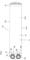
- the drawings show a cooling component 10, as is used, for example, in the context of cooling battery or accumulator systems of electric vehicles in order to cool the respective batteries or the individual cells.
- Such a cooling component 10 is usually part of a higher-level cooling device, which ensures that cooling medium is continuously guided through the cooling component 10, which absorbs waste heat from the object to be cooled and then dissipates it.
- the components of the cooling device required for this, such as a suitable pump, inlet and outlet lines for the cooling medium, etc., are known in the prior art and are therefore not explained in more detail.
- the cooling component 10 can be connected in use to identical additional cooling components (not shown) of the cooling device, which can then cool several objects to be cooled at the same time, for example several batteries or battery cells.
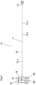
- the cooling component 10 has a heat sink 11 made of metal, in the present case made of aluminum, which rests against the object to be cooled during use or is at least arranged immediately adjacent to it.
- the heat sink 11 is elongated, in the present case essentially as a (very) flat cuboid.
- a connecting part 12 is arranged at one end thereof, via which cooling medium, such as cooling water or the like, can be supplied to the cooling component 10 within a first group 14 a of elongated medium channels 14 is then guided in the main extension direction of the heat sink 11 or in the longitudinal direction to the other end of the heat sink 11, then deflected in a deflection cap 13 arranged at the other end of the cooling component 10 or the heat sink 11 is and flows in the opposite direction through a second group 14 b of elongated medium channels in the opposite direction through the heat sink 10 until it reaches the connecting part 12 again and is led out or discharged from the cooling component 10 via the connecting part 12.
- cooling medium such as cooling water or the like
- the cooling medium On its way through the heat sink 11 or the medium channels 14, the cooling medium absorbs the waste heat of the object to be cooled during operation of the cooling device or the cooling component 10 and transports it away.
- the heat sink 11 is made in one piece. This can be a profile body or a profile piece (pocket profile) that was produced using the (aluminum) extrusion process.
- the heat sink 11 in the present case has four heat sink outer walls 15, namely a first large-area, upper wall 15 a, a second large-area lower wall 15 b, which is parallel to the upper wall at a distance, and two parallel to one another, the upper wall 15 a and the lower wall 15 b each connecting narrow side walls 15 c and 15 d.
- the (elongated) medium channels 14 are arranged inside the heat sink 11, i.e. inside the space enclosed by the outer body walls 15.
- the medium channels 14 extend parallel to the main extension direction of the heat sink 11 or parallel to the narrow side walls 15c and 15d. Based on a cross section through heat sink 11, the individual medium channels 14 are arranged in a row next to each other.
- Each (elongated) medium channel 14 is further limited by medium channel walls 16 on (all) its longitudinal sides (based on the main extension direction of the respective medium channel 14). In the present case, this is specifically done by two pairs of medium channel walls 16, each spaced apart from one another.
- Each medium channel 14 is delimited on two opposite longitudinal sides (vertical or perpendicular to the upper and lower large walls 15 a and 15 b), namely in the transverse direction or perpendicular to the main extension direction of the heat sink 11, by a first pair of two medium channel walls 16 arranged at a distance from one another and each running parallel to one another in the main extension direction of the heat sink.
- one of these medium channel walls 16 of this first pair is formed by the respective outer body wall 15 of the heat sink 11, in this case the narrow side wall 15 c or the narrow side wall 15 d.
- Each (elongated) medium channel 14 is further limited on its other two longitudinal sides by a different pair of medium channel walls 16, in which one medium channel wall 16 of the pair is formed by the upper large-area wall 15 a, the other medium channel wall 16 of the pair by the lower large wall 15 b.
- each medium channel 14 is also open at both ends or transverse sides, namely on the transverse sides 17a and 17b. In other words, there is no wall there, so that cooling medium can flow into or out of the medium channel 14 through the transverse sides 17a and 17b.
- the connecting part 12 has an inlet chamber 18 with an (upper) inlet opening 19, via which cooling medium can be supplied to the medium channels 14 of the first group 14a of medium channels 14.
- the open transverse sides 17a of the medium channels 14 of the first group 14a of medium channels 14 are arranged within the inlet chamber 18, so that the cooling medium directly from the inlet chamber 18 into/via the open transverse sides 17a into the medium channels 14 of this first group 14 a can flow.
- the connecting part 12 also has an outlet chamber 20, which is separate from the inlet chamber 18 and has an outlet opening 21, via which cooling medium can be removed from the medium channels 14 of the second group 14b of medium channels 14.
- the open transverse sides 17 a of the medium channels 14 of the second group 14 b of medium channels are arranged within the drain chamber 20, so that the cooling medium can flow directly from the drain chamber 18 into/via the open transverse sides 17a into the medium channels 14 of this second group 14b.
- the main direction of extension of the medium channels 14 runs perpendicular to the main direction of extension or main flow direction of the inlet chamber 18 and also the outlet chamber 20.
- one in the inlet chamber 18 is presently integral with the connecting part 12 connected fluid guide wall 22 which extends at least in some areas at an angle to the main flow direction or main extension direction of the inlet chamber 18 (and in particular is curved at least in some areas in the direction of the inlet opening 19).
- the inlet opening 19 is located at one end of the inlet chamber 18, and at another end there is a connection opening 33, to which a connection part of an identical further cooling component (not shown) can be connected, in particular for connecting the inlet opening of the further cooling component the connection opening 33.
- the drain opening 21 is located in an analogous manner at one end of the drain chamber 20 and at another end of a connection opening 34 of the drain chamber 20, to which a connecting part of an identical further cooling component can be connected, in particular for connecting the drain opening 21 of the further cooling component to the connecting opening 34 .
- the cooling component 10 or in the present case the connecting part 12 also has connecting means 35, in particular locking means, for releasably connecting the cooling component to an identical further cooling component.
- connecting means 35 in particular locking means, for releasably connecting the cooling component to an identical further cooling component.
- both the connecting part 12 and the deflection cap 13 are not made of metal (or possibly a metal alloy), but rather of plastic.
- these components are each designed in one piece and manufactured as a plastic injection-molded part, for example made of thermoplastic.
- the heat sink 11 on the one hand and the connecting part 12 or the deflection cap 13 on the other hand are firmly connected to one another in a fluid-tight manner.
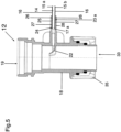
- a first, terminal connection region 23 a of the heat sink 11 is inserted into a receiving space 24 of a (hollow cuboid-shaped) (in the present case matching the first, essentially cuboid-shaped connection region 23 a of the heat sink 11).
- Receptacle 25 of the connecting part 12 is introduced and fluid-tightly connected there to the inside of the receptacle 25, namely with connecting surfaces 27 of the receptacle 25 arranged on the inside.
- the metallic heat sink 11 (also) has connecting surfaces, namely connecting surfaces 26 in the first connecting region 23 a.
- Each of these (metallic) connecting surfaces 26 of the heat sink 11 each have three-dimensional nano- and/or microstructures introduced into the respective surface by physical and/or chemical nano- or micro-structuring processes (such as chemical etching or laser beam structuring).
- the connecting surfaces 26 of the heat sink 11 are specifically arranged on the outer sides of the body outer walls 15, namely, as already mentioned, in each case in the first connection region 23 a, that is to say in that end region or end section of the heat sink 11 which is in the receiving space 24 of the Recording 25 is introduced and the walls 28 directly adjacent to the receptacle 25 forming or to the walls 28 which form or delimit the receiving space 24.
- Each of the connecting surfaces 26 of the heat sink 11 structured in the manner described lies opposite an associated connecting surface 27 of the receptacle 25 and is connected to it, namely pressed (using thermal direct joining), as will be explained in more detail below.
- the deflection cap 13 is also connected to the heat sink 11 in a similar manner.
- the heat sink 11 has a second connection area 23 b at its other end, on which the deflection cap 13 is seated, also with a plurality of connection surfaces 26 and with each in particular by the mentioned physical and / or chemical nano- or micro-structuring processes in the respective Three-dimensional nano- and/or microstructures introduced onto the surface.
- the deflection cap 13 - similar to the connecting part 12 - also has a receptacle 31 with a receiving space 30, into which the second connection region 23 b of the heat sink 11 is introduced, and is there - in a manner analogous to that above for the connection of heat sink 11 and receptacle 25 of the connecting part 12 described - connected in a fluid-tight manner to the receptacle 31 of the deflection cap 13 in that each connecting surface 26 of the heat sink 11 is opposite an associated connecting surface of the receptacle 31 and is pressed with it in the manner described.
- the medium channels 14 also have open transverse sides 17 b in the area of the other end of the heat sink 11, these open transverse sides 17 b being arranged in a deflection space 36 of the deflection cap 13.
- the deflection cap 13 is designed in such a way that cooling medium, which flows from the open transverse sides 17 b of the first group 14 a of medium channels 14 arranged in this area of the other end into the deflection space 36, flows in the deflection space 36 to the open sides 17 b of the Medium channels 14 of the second group 14 b of medium channels 14 is deflected, enters these and then flows back in the opposite direction - in the second group 14 b of medium channels - through the heat sink 11 to the connecting part 12.
- the heat sink 11, the connecting part 12 and the deflection cap 13 are prefabricated separately.
- the aforementioned components 11, 12, 13 are then connected to one another. This will be described below using an example of the connection of the connecting part 12 to the heat sink 11.
- the heat sink 11 is connected to the deflection cap 13 in an analogous manner.
- these two components are first moved relative to one another. For example, by holding the connecting part 12 stationary and moving the heat sink 11 in the direction of the connecting part 12 by means of a suitable conveying element. It goes without saying that the process can also work in reverse or that both components can be moved towards each other.
- the heat sink 11 is then moved relative to the connecting part 12 in such a way that the first connection region 23 a of the heat sink is placed precisely in the receptacle 25 or the receptacle space 24 in such a way that each of the connection surfaces 26 of the first connection region 23 a of the heat sink 11 is opposite an associated connecting surface 27 of the receptacle 25 of the connecting part 12.
- the metallic heat sink 11, or at least the connecting surfaces 26 of the first connection region 23 a of the heat sink 11, are heated to a temperature, in particular by means of an induction heater known in the prior art (other heating techniques are of course also conceivable), heated to a temperature or heated, which corresponds at least to the softening temperature or the melting temperature of the plastic of the connecting part 12 or the receptacle 25 of the connecting part 12.
- the heat of the heat sink 11 is transferred to the connecting part 12 or its connecting surfaces 27 when the first connection region 23 a of the heat sink 11 is at its desired end position in the receptacle 25, which then leads to the connecting surfaces 27 melting.
- a pressing element such as a pressing jaw (not shown), which presses from the outside onto the walls 28 of the receptacle 25 to be connected, then during and/or immediately before and/or immediately after the melting the respective connecting surface 27 of the receptacle 25 arranged on the inside of the respective wall 28 of the receptacle 25 is pressed or pressed against the respective (structured) connecting surface 26 of the heat sink 11 and thus connected to it in a fluid-tight manner (thermal direct joining).
- a pressing element such as a pressing jaw (not shown)
- a pair of spaced-apart connecting surfaces 26 of the heat sink 11 is connected to the corresponding opposite walls by an alternative press fit.
- the connecting surfaces 26 of the narrow side walls 15 c, 15 d or the connecting surfaces 26 arranged on the narrow side walls 15 c, 15 d could be pressed with the connecting surfaces 27 of the walls 28 of the receptacle 25 of the connecting part 12 lying opposite them, in advance of the connection the distance between the connecting surfaces 26 of the narrow side walls 15 c, 15 d from one another is or will be coordinated with the distance between the opposite connecting surfaces 27 of the connecting part 12 in such a way that the connecting surfaces 26, when they are later already in the exact position or in their respective end position in the receiving space 24 of the connecting part 12 are located, by heating the connecting surfaces 26 of the heat sink 11 (which only takes place in this position) so that they thermally expand (i.e.
- connecting surfaces 27 of the receptacle 25 are pressed with the opposite connecting surfaces 26 of the heat sink 11 by a respective pressing element, which are each opposite the first large-area wall 15 a or the second large-area wall 15 b of the heat sink 11 , and that the other connecting surfaces 27 of the receptacle 25, which are each opposite the connecting surface 26 of the respective narrow side wall 15 c or 15 d of the heat sink 11, through the above Press fit can be connected to the respective connecting surface 26 of the heat sink 11.
- Cooling component 24 Recording room connection part 11 Heat sink 25 Recording connection part 12 Connection part 26 Connecting surfaces heat sink 13 deflection cap 27 Connection surfaces recording 14 Medium channel Connection part 14.1 External medium channel 28 Walls recording 14.2 External medium channel 30
- Recording space deflection cap 14 a first group of media channels 31 Recording deflection cap 14 b second group of media channels 32 Connection surfaces recording 15 outer body walls deflection cap 15 a first large wall 33 Connection opening inlet chamber 15 b second large wall 34 Drain chamber connection opening 15c Narrow side wall 35 lanyard 15 d Narrow side wall 36 Deflection space deflection cap 16 Medium channel wall 17 a open transverse side 17 b open transverse side 18 Inlet chamber 19 Inlet opening 20 drain chamber 21 Drain opening 22 Fluid guide wall 23 a first connection area Heat sink 23 b second connection area Heat sink
Landscapes
- Engineering & Computer Science (AREA)
- Physics & Mathematics (AREA)
- Thermal Sciences (AREA)
- Mechanical Engineering (AREA)
- General Engineering & Computer Science (AREA)
- Microelectronics & Electronic Packaging (AREA)
- Cooling Or The Like Of Semiconductors Or Solid State Devices (AREA)
- Moulds For Moulding Plastics Or The Like (AREA)
- Heat Treatment Of Strip Materials And Filament Materials (AREA)
- Heat Treatments In General, Especially Conveying And Cooling (AREA)
- Secondary Cells (AREA)
Priority Applications (1)
| Application Number | Priority Date | Filing Date | Title |
|---|---|---|---|
| EP24174016.6A EP4386304B1 (fr) | 2022-07-18 | 2023-07-05 | Composant de refroidissement |
Applications Claiming Priority (2)
| Application Number | Priority Date | Filing Date | Title |
|---|---|---|---|
| DE102022117863 | 2022-07-18 | ||
| DE102023115116.9A DE102023115116A1 (de) | 2022-07-18 | 2023-06-09 | Kühlbauteil und Verfahren zur Herstellung desselben |
Related Child Applications (2)
| Application Number | Title | Priority Date | Filing Date |
|---|---|---|---|
| EP24174016.6A Division EP4386304B1 (fr) | 2022-07-18 | 2023-07-05 | Composant de refroidissement |
| EP24174016.6A Division-Into EP4386304B1 (fr) | 2022-07-18 | 2023-07-05 | Composant de refroidissement |
Publications (3)
| Publication Number | Publication Date |
|---|---|
| EP4310432A1 true EP4310432A1 (fr) | 2024-01-24 |
| EP4310432B1 EP4310432B1 (fr) | 2026-05-13 |
| EP4310432C0 EP4310432C0 (fr) | 2026-05-13 |
Family
ID=87158101
Family Applications (2)
| Application Number | Title | Priority Date | Filing Date |
|---|---|---|---|
| EP24174016.6A Active EP4386304B1 (fr) | 2022-07-18 | 2023-07-05 | Composant de refroidissement |
| EP23183576.0A Active EP4310432B1 (fr) | 2022-07-18 | 2023-07-05 | Composant de refroidissement et son procédé de fabrication |
Family Applications Before (1)
| Application Number | Title | Priority Date | Filing Date |
|---|---|---|---|
| EP24174016.6A Active EP4386304B1 (fr) | 2022-07-18 | 2023-07-05 | Composant de refroidissement |
Country Status (4)
| Country | Link |
|---|---|
| US (2) | US12460881B2 (fr) |
| EP (2) | EP4386304B1 (fr) |
| JP (1) | JP2024012263A (fr) |
| KR (1) | KR20240011097A (fr) |
Cited By (1)
| Publication number | Priority date | Publication date | Assignee | Title |
|---|---|---|---|---|
| WO2025191123A1 (fr) | 2024-03-15 | 2025-09-18 | Erwin Quarder Systemtechnik Gmbh | Connecteur enfichable, ensemble connecteur, dispositif de refroidissement, procédé et utilisation |
Families Citing this family (3)
| Publication number | Priority date | Publication date | Assignee | Title |
|---|---|---|---|---|
| US20250003702A1 (en) * | 2023-06-28 | 2025-01-02 | Valeo Systemes Thermiques | Tube end adapter |
| FR3161507B1 (fr) * | 2024-04-22 | 2026-04-17 | Valeo Systemes Thermiques | Dispositif de régulation thermique avec collecteur central |
| EP4737840A1 (fr) * | 2024-10-29 | 2026-05-06 | Volvo Car Corporation | Raccord pour la connexion fluidique d'un canal de refroidissement inter-cellules à un système de tuyauterie |
Citations (4)
| Publication number | Priority date | Publication date | Assignee | Title |
|---|---|---|---|---|
| US20140090812A1 (en) * | 2012-09-28 | 2014-04-03 | Behr Gmbh & Co., Kg | Heat exchanger |
| DE102016125859A1 (de) * | 2016-01-04 | 2017-07-06 | Lisa Dräxlmaier GmbH | Wärmetauscher für eine elektrische Komponente wie eine Batterie oder einer Leistungselektronik in einem Kraftfahrzeug sowie Herstellungsverfahren |
| US20170343144A1 (en) * | 2016-05-31 | 2017-11-30 | Mitchell W. Hunt | Fluid Connector Assembly |
| EP3885689A1 (fr) * | 2020-03-26 | 2021-09-29 | A. Raymond et Cie | Connecteur conçu pour être connecté à un tube extrudé à ports multiples |
Family Cites Families (6)
| Publication number | Priority date | Publication date | Assignee | Title |
|---|---|---|---|---|
| EP3167346A4 (fr) * | 2014-07-08 | 2018-01-24 | ADC Technologies Inc. | Agencement de refroidissement amélioré pour appareil serveur |
| JP6513427B2 (ja) * | 2015-02-27 | 2019-05-15 | 昭和電工株式会社 | 液冷式冷却装置 |
| DE102017210343A1 (de) * | 2017-06-21 | 2018-12-27 | Robert Bosch Gmbh | Flexible Kühlplatte für eine Batterie |
| DE102018216720A1 (de) * | 2018-09-28 | 2020-04-02 | Robert Bosch Gmbh | Kühlplatte zur Temperierung zumindest einer Batteriezelle und Batteriesystem |
| KR102169412B1 (ko) * | 2019-02-19 | 2020-10-23 | 주식회사 고산 | 차량의 전기소자 냉각용 열교환기 |
| NO345706B1 (en) * | 2019-03-15 | 2021-06-21 | Hydro Extruded Solutions As | Multi Port Extrusion (MPE) connection to a header |
-
2023
- 2023-07-05 EP EP24174016.6A patent/EP4386304B1/fr active Active
- 2023-07-05 EP EP23183576.0A patent/EP4310432B1/fr active Active
- 2023-07-07 JP JP2023112153A patent/JP2024012263A/ja active Pending
- 2023-07-14 US US18/222,251 patent/US12460881B2/en active Active
- 2023-07-14 KR KR1020230091510A patent/KR20240011097A/ko active Pending
-
2025
- 2025-09-11 US US19/325,840 patent/US20260009604A1/en active Pending
Patent Citations (4)
| Publication number | Priority date | Publication date | Assignee | Title |
|---|---|---|---|---|
| US20140090812A1 (en) * | 2012-09-28 | 2014-04-03 | Behr Gmbh & Co., Kg | Heat exchanger |
| DE102016125859A1 (de) * | 2016-01-04 | 2017-07-06 | Lisa Dräxlmaier GmbH | Wärmetauscher für eine elektrische Komponente wie eine Batterie oder einer Leistungselektronik in einem Kraftfahrzeug sowie Herstellungsverfahren |
| US20170343144A1 (en) * | 2016-05-31 | 2017-11-30 | Mitchell W. Hunt | Fluid Connector Assembly |
| EP3885689A1 (fr) * | 2020-03-26 | 2021-09-29 | A. Raymond et Cie | Connecteur conçu pour être connecté à un tube extrudé à ports multiples |
Cited By (1)
| Publication number | Priority date | Publication date | Assignee | Title |
|---|---|---|---|---|
| WO2025191123A1 (fr) | 2024-03-15 | 2025-09-18 | Erwin Quarder Systemtechnik Gmbh | Connecteur enfichable, ensemble connecteur, dispositif de refroidissement, procédé et utilisation |
Also Published As
| Publication number | Publication date |
|---|---|
| EP4386304A3 (fr) | 2024-06-26 |
| EP4386304B1 (fr) | 2026-07-01 |
| EP4386304A2 (fr) | 2024-06-19 |
| US12460881B2 (en) | 2025-11-04 |
| EP4310432B1 (fr) | 2026-05-13 |
| US20240019219A1 (en) | 2024-01-18 |
| EP4310432C0 (fr) | 2026-05-13 |
| KR20240011097A (ko) | 2024-01-25 |
| US20260009604A1 (en) | 2026-01-08 |
| JP2024012263A (ja) | 2024-01-30 |
Similar Documents
| Publication | Publication Date | Title |
|---|---|---|
| EP4310432B1 (fr) | Composant de refroidissement et son procédé de fabrication | |
| DE102012005871A1 (de) | Kühlvorrichtung für eine Fahrzeugbatterie sowie Fahrzeugbatterie mit Kühlvorrichtung | |
| DE69502264T2 (de) | Körper und Verbindung zur Kühlung eines elektronischen Bausteines durch eine von ihm elektrisch isolierte Flüssigkeit | |
| DE102012005870A1 (de) | Kühlvorrichtung für eine Fahrzeugbatterie sowie Fahrzeugbatterie mit Kühlvorrichtung | |
| DE69615946T2 (de) | Verfahren zur Herstellung von Tunnelplatten-Wärmerohren | |
| EP2701190B1 (fr) | Procédé de fabrication d'un corps de refroidissement pour au moins un élément à refroidir | |
| EP1840494A2 (fr) | Profilé d'échangeur de chaleur | |
| EP0566899B1 (fr) | Echangeur de chaleur, notamment évaporateur | |
| WO2015027995A1 (fr) | Système de refroidissement | |
| DE112008002853B4 (de) | Gerippte Widerstandspunktschweißelektrode | |
| WO2012080488A1 (fr) | Dispositif de thermorégulation, outil de coulée et procédé de fabrication d'une pièce coulée | |
| DE102020211612A1 (de) | Temperiermodul für eine Batterie, insbesondere Fahrzeugbatterie | |
| DE69603383T2 (de) | Wärmetauscher und Verfahren zu seiner Herstellung | |
| DE19854932C2 (de) | Vakuum-Außenkalibrierung | |
| DE102023115116A1 (de) | Kühlbauteil und Verfahren zur Herstellung desselben | |
| WO2022058181A1 (fr) | Dispositif de régulation de la température d'un élément et son procédé de fabrication | |
| DE10151238A1 (de) | Kältemittel/Luft-Wärmeaustauschernetz | |
| DE102019209155A1 (de) | Energiespeicheranordnung | |
| DE112016002244B4 (de) | Wärmetauscher und Herstellungsverfahren hierfür | |
| DE2012441A1 (de) | Rohrförmiges Wärmetauscherelement und mit diesem hergestellte Wärmetauscher | |
| EP4369391A1 (fr) | Dispositif de refroidissement | |
| DE102023210493A1 (de) | Heatpipekühlkörper | |
| EP4689522B1 (fr) | Dispositif de refroidissement et procédé de son fabrication | |
| WO2008003291A1 (fr) | Élément chauffant, en particulier radiateur à tubes | |
| DE20205200U1 (de) | Hohlkammerprofil aus Metall insbesondere für Wärmetauscher und Verformungsvorrichtung |
Legal Events
| Date | Code | Title | Description |
|---|---|---|---|
| PUAI | Public reference made under article 153(3) epc to a published international application that has entered the european phase |
Free format text: ORIGINAL CODE: 0009012 |
|
| STAA | Information on the status of an ep patent application or granted ep patent |
Free format text: STATUS: THE APPLICATION HAS BEEN PUBLISHED |
|
| AK | Designated contracting states |
Kind code of ref document: A1 Designated state(s): AL AT BE BG CH CY CZ DE DK EE ES FI FR GB GR HR HU IE IS IT LI LT LU LV MC ME MK MT NL NO PL PT RO RS SE SI SK SM TR |
|
| STAA | Information on the status of an ep patent application or granted ep patent |
Free format text: STATUS: REQUEST FOR EXAMINATION WAS MADE |
|
| 17P | Request for examination filed |
Effective date: 20240503 |
|
| RBV | Designated contracting states (corrected) |
Designated state(s): AL AT BE BG CH CY CZ DE DK EE ES FI FR GB GR HR HU IE IS IT LI LT LU LV MC ME MK MT NL NO PL PT RO RS SE SI SK SM TR |
|
| GRAP | Despatch of communication of intention to grant a patent |
Free format text: ORIGINAL CODE: EPIDOSNIGR1 |
|
| STAA | Information on the status of an ep patent application or granted ep patent |
Free format text: STATUS: GRANT OF PATENT IS INTENDED |
|
| INTG | Intention to grant announced |
Effective date: 20260123 |
|
| GRAS | Grant fee paid |
Free format text: ORIGINAL CODE: EPIDOSNIGR3 |
|
| GRAA | (expected) grant |
Free format text: ORIGINAL CODE: 0009210 |
|
| STAA | Information on the status of an ep patent application or granted ep patent |
Free format text: STATUS: THE PATENT HAS BEEN GRANTED |
|
| AK | Designated contracting states |
Kind code of ref document: B1 Designated state(s): AL AT BE BG CH CY CZ DE DK EE ES FI FR GB GR HR HU IE IS IT LI LT LU LV MC ME MK MT NL NO PL PT RO RS SE SI SK SM TR |
|
| REG | Reference to a national code |
Ref country code: CH Ref legal event code: F10 Free format text: ST27 STATUS EVENT CODE: U-0-0-F10-F00 (AS PROVIDED BY THE NATIONAL OFFICE) Effective date: 20260513 Ref country code: GB Ref legal event code: FG4D Free format text: NOT ENGLISH |
|
| REG | Reference to a national code |
Ref country code: DE Ref legal event code: R096 Ref document number: 502023004108 Country of ref document: DE |
|
| REG | Reference to a national code |
Ref country code: IE Ref legal event code: FG4D Free format text: LANGUAGE OF EP DOCUMENT: GERMAN |
|
| REG | Reference to a national code |
Ref country code: CH Ref legal event code: W10 Free format text: ST27 STATUS EVENT CODE: U-0-0-W10-W00 (AS PROVIDED BY THE NATIONAL OFFICE) Effective date: 20260624 |
|
| RAP4 | Party data changed (patent owner data changed or rights of a patent transferred) |
Owner name: ERWIN QUARDER SYSTEMTECHNIK GMBH |
|
| U01 | Request for unitary effect filed |
Effective date: 20260612 |
|
| U07 | Unitary effect registered |
Designated state(s): AT BE BG DE DK EE FI FR IT LT LU LV MT NL PT RO SE SI Effective date: 20260624 |
|
| U20 | Renewal fee for the european patent with unitary effect paid |
Year of fee payment: 4 Effective date: 20260624 |