EP4310880B1 - Système électromécanique à segment rotatif avec augmentation de la résistance - Google Patents
Système électromécanique à segment rotatif avec augmentation de la résistance Download PDFInfo
- Publication number
- EP4310880B1 EP4310880B1 EP22186400.2A EP22186400A EP4310880B1 EP 4310880 B1 EP4310880 B1 EP 4310880B1 EP 22186400 A EP22186400 A EP 22186400A EP 4310880 B1 EP4310880 B1 EP 4310880B1
- Authority
- EP
- European Patent Office
- Prior art keywords
- coil
- rotating member
- lobe
- pole
- electromechanical system
- Prior art date
- Legal status (The legal status is an assumption and is not a legal conclusion. Google has not performed a legal analysis and makes no representation as to the accuracy of the status listed.)
- Active
Links
Images


Classifications
-
- H—ELECTRICITY
- H01—ELECTRIC ELEMENTS
- H01H—ELECTRIC SWITCHES; RELAYS; SELECTORS; EMERGENCY PROTECTIVE DEVICES
- H01H50/00—Details of electromagnetic relays
- H01H50/16—Magnetic circuit arrangements
-
- H—ELECTRICITY
- H01—ELECTRIC ELEMENTS
- H01H—ELECTRIC SWITCHES; RELAYS; SELECTORS; EMERGENCY PROTECTIVE DEVICES
- H01H50/00—Details of electromagnetic relays
- H01H50/16—Magnetic circuit arrangements
- H01H50/18—Movable parts of magnetic circuits, e.g. armature
- H01H50/24—Parts rotatable or rockable outside coil
-
- H—ELECTRICITY
- H01—ELECTRIC ELEMENTS
- H01F—MAGNETS; INDUCTANCES; TRANSFORMERS; SELECTION OF MATERIALS FOR THEIR MAGNETIC PROPERTIES
- H01F7/00—Magnets
- H01F7/06—Electromagnets; Actuators including electromagnets
- H01F7/08—Electromagnets; Actuators including electromagnets with armatures
- H01F7/121—Guiding or setting position of armatures, e.g. retaining armatures in their end position
- H01F7/122—Guiding or setting position of armatures, e.g. retaining armatures in their end position by permanent magnets
-
- H—ELECTRICITY
- H01—ELECTRIC ELEMENTS
- H01F—MAGNETS; INDUCTANCES; TRANSFORMERS; SELECTION OF MATERIALS FOR THEIR MAGNETIC PROPERTIES
- H01F7/00—Magnets
- H01F7/06—Electromagnets; Actuators including electromagnets
- H01F7/08—Electromagnets; Actuators including electromagnets with armatures
- H01F7/14—Pivoting armatures
- H01F7/145—Rotary electromagnets with variable gap
-
- H—ELECTRICITY
- H01—ELECTRIC ELEMENTS
- H01H—ELECTRIC SWITCHES; RELAYS; SELECTORS; EMERGENCY PROTECTIVE DEVICES
- H01H50/00—Details of electromagnetic relays
- H01H50/16—Magnetic circuit arrangements
- H01H50/18—Movable parts of magnetic circuits, e.g. armature
-
- H—ELECTRICITY
- H01—ELECTRIC ELEMENTS
- H01H—ELECTRIC SWITCHES; RELAYS; SELECTORS; EMERGENCY PROTECTIVE DEVICES
- H01H50/00—Details of electromagnetic relays
- H01H50/16—Magnetic circuit arrangements
- H01H50/36—Stationary parts of magnetic circuit, e.g. yoke
-
- H—ELECTRICITY
- H01—ELECTRIC ELEMENTS
- H01H—ELECTRIC SWITCHES; RELAYS; SELECTORS; EMERGENCY PROTECTIVE DEVICES
- H01H51/00—Electromagnetic relays
- H01H51/22—Polarised relays
- H01H51/2236—Polarised relays comprising pivotable armature, pivoting at extremity or bending point of armature
-
- H—ELECTRICITY
- H01—ELECTRIC ELEMENTS
- H01H—ELECTRIC SWITCHES; RELAYS; SELECTORS; EMERGENCY PROTECTIVE DEVICES
- H01H2225/00—Switch site location
- H01H2225/006—Switch site location more then one pole
Definitions
- the present invention relates to electromechanical systems, and more particularly, to electromechanical systems of a rotary type.
- Electro-mechanical systems are commonly used to operate contactors and relays as they present several advantages, such as the simplicity of design and operating reliability, over other types of actuating systems.
- common types of conventional electro-mechanical systems include a magnetic circuit having an iron core, a magnetic yoke, and an armature, and an energizing coil responsible for applying a magnetic flux onto the magnetic circuit under supply of an energizing current.
- the elements of the magnetic circuit are in general designed and arranged relatively to each other so that the magnetic flux generated by the energized coil is directed through the magnetic circuit to exert an attractive force onto a respective side of the armature, thereby causing the armature to move or rotate in the direction of the attractive force.
- it is possible to induce a switching operation of the armature between different states by controlling the sign and intensity of the external current supplied to the energizing coil.
- Rotary electro-mechanical systems have advantages for use in certain applications, for e.g. where an improvement in operation torque and operation stability is desired, such as provided by ball-rotation and inclined-rotation electro-mechanical systems, respectively.
- a rotary electromagnetic system of a ball-rotation type is described in international patent application publication WO 2018/234142A1 .
- this known electromagnetic system the plunging of an iron core through a classical solenoid construction is converted into a rotary motion of an armature via additional mechanical elements (balls) moving on an inclined plane (curved path).
- the electromagnetic system includes a magnetic yoke, a coil, a lower iron core, a top plate, an upper iron core, an armature, a magnetic isolation ring that magnetically isolates the upper iron core from the top plate and a plurality of balls.
- the upper iron core is able move in a vertical direction with respect to the magnetic isolation ring.
- a plurality of first curved grooves are formed in the bottom surface of the armature, and a plurality of second curved grooves, corresponding to the plurality of first curved grooves respectively, are formed in the top surface of the top plate.
- the ball may roll in the first curved groove and the corresponding second curved groove.
- Each first curved grooves has a depth gradually deepened from a first end to a second end, such that the force applied on the armature by the ball is inclined with respect to a central axis of the upper iron core for driving the armature to rotate around the central axis, which is parallel to the vertical direction.
- the linear movement of the core is thus converted into a rotational motion of the armature by the balls moving on an inclined plane which is defined by the curved path of the grooves. This implies that the transmission ratio between the vertical movement of the core and the armature rotational movement is very large, which leads to being necessary to have extremely precise components available.
- this design may present a very high gear rate and therefore, required that extremely precise components are available.
- the extreme demands on the precision of the individual parts and manufacturing may not be met in practice or justifiable for every application.
- the functionality of this design is strongly dependent on the mounting direction, since the balls may lose their position, especially in a lateral assembly position. This might result in operation failures.
- the present invention has been made in view of the shortcomings and disadvantages of the prior art, and an object thereof is to provide an electromechanical system for electrical switching devices that is capable of offering a direct, rotating actuation of an armature in a rotation movement limited by a desired maximum rotation angle, and offering hereby a torque performance suitable for contact systems of electromechanical relays, such as DC power switches.
- a further object is to provide an electrical switching device comprising the electromechanical system.
- the shape contour of the at least one first end portion has the shape of a step recess with the curved side wall which is defined by a circular segment of a given length on a plane transverse to the central axis.
- the rotation motion is stopped at the predetermined rotation angle which is a maximum angle of rotation at which there is full overlapping contact between the matching shape contours of the facing lobe and the first end portion; and/or the length and radius of the circular segment of the shape contour is adapted to limit the rotation motion executed by the rotating member to a maximum angle of rotation equal to or less than 45°.
- the magnetic system further comprises: a permanent magnet provided on at least one of the first end portions of the first and second pole members, the permanent magnet being arranged facing the respective lobe of the rotating member and magnetically polarized to reduce reluctance across a separation gap between the first end portion on which it is arranged and the facing lobe.
- said shape contour is provided in only one of the first portions of the first and second pole members, and the permanent magnet is provided on the other one of the first portions of the first and second pole members.
- the rotating member is adapted to adopt an open state which is a rotation orientation at which the first and second lobes are respectively separated from the first end portions of the first and second pole members by respective maximum separation gaps when the energizing coil assembly is not energized; and/or the rotating member is adapted to rotate by a predetermined rotation angle to a closed state when the energizing coil assembly is energized by a given energizing current, wherein in the closed state at least one of the first and second lobes of the rotating member fully abuts against the facing first end portion of the respective first and second pole members.
- said predetermined rotation angle is equal to or less than 45°.
- first and second pole members have respective second end portions that penetrate from the upper side of the respective first and second coils into an inner space of the respective first and second coils.
- At least one of the first and second pole members have a U-shape form arranged with downwards legs with respect to the upper side of the first and second coils, the leg comprising the first end portion extending outside the first and second coils.
- the magnetic system further comprises: a main core arranged on a lower side of the first and second coils and configured to connect the first pole member to the second pole member, wherein the main core, the first pole member, the rotating member and the second pole member form said magnetic flux path provided by the magnetic system.
- the main core has a U-shape formed by a central region and a pair of first and second legs that extend upwards from respective sides of said central region, wherein the first leg penetrates through the inner space of the first coil and the second leg penetrates through the inner space of the second coil, from the lower side of the first and second coils, extending upwards until contacting with the respective second end portions of the first and second pole members.
- the magnetic system further comprises: an auxiliary core adapted to increase the confinement of magnetic flux lines inside the inner space of the first and second coils, wherein the auxiliary core is adapted to extend along the axial length of the first and second coils and an inner side of the main core; wherein the main core and/or the auxiliary core may be made as a single piece or a plurality of pieces magnetically coupled to each other; and/or wherein the main core and/or the auxiliary core are made of soft iron, in solid or laminated form; and/or wherein the rotating member is made of soft iron.
- an electrical switching device comprising the rotary-segment electromechanical system.
- the electrical switching device is a contactor or a relay.
- a general concept underlying the present invention lies in providing a rotary-segment electromechanical system having a magnetic system comprising a rotating member, for e.g. a rotor made of soft iron, which executes, within a special arrangement of magnetic yokes and pole plates, a rotation motion with a maximum angle of rotation which is solely limited by the pole plates.
- the electromechanical system includes an energizing coil assembly with two coil towers that carry a pair of coil windings, each wound in a respective tower by flyer winding or other suitable coil winding techniques known in the art so as to generate magnetic fields of opposed direction.
- the rotating member and at least one of the pole plates are designed with a special geometry, hereinafter called reluctance-boost shape contour, which is designed such that the torque generated on the rotating member when the coils are energized matches a force curve of a conventional hinged-armature magnet system, and which can especially map the high force requirements in the contact over-travel region.
- reluctance-boost shape contour which is designed such that the torque generated on the rotating member when the coils are energized matches a force curve of a conventional hinged-armature magnet system, and which can especially map the high force requirements in the contact over-travel region.
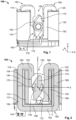
- Fig. 1 is a schematic perspective view of a rotary-segment electromechanical system 100 according to an exemplary embodiment of the present invention.
- the direction of the Z axis in the XYZ coordinate axes system shown in Fig. 1 will be referred to hereafter as the vertical direction.
- the following description of the present invention and exemplary embodiments are not to be construed as being limited to their use in a particular orientation, such as in the vertical orientation defined by gravity.
- the rotary-segment electromechanical system 100 comprises an energizing coil assembly for generating a magnetic field when energized with an external excitation current (not shown).
- the energizing coil assembly includes a first coil 110 and a second coil 120 which are aligned with the respective coil axis in parallel to each other and disposed spaced apart in a direction transverse to the coil axes by a spacing region 130.
- coil axis is used here when referring to a coil symmetry axis that passes across the center of the first coil 110 (or second coil 120) and is aligned along the Z-axis shown in Fig. 1 .
- the first coil 110 is a set of windings wound around a first coil support or tower 115 of a support body 140 of the electromechanical system 100.
- the second coil 120 is a set of windings wound around a second, vertical tower 116 of the support body 140.
- the windings of the first coil 110 are wound in the sense opposite to the windings of the second coil 120 so as to generate magnetic field lines within its inner center that are oriented in an direction opposite to the magnetic field lines generated by the second coil 120 within its inner center when both first and second coils are energized by a same excitation current or separate excitations currents of a same polarity.
- the first and second coils 110 and 120 may be connected either in series or in parallel so as to be energized by a common power supply (not shown). In an alternative configuration, the first and second coils 110 and 120 may be energized by separate energizing currents, the direction and intensity of the magnetic field generated by each coil being then determined by the respective energizing currents.
- the first and second coils 110 and 120 are preferably provided with similar characteristics, such as number of windings, impedance, length and cross-section of the coils, which allows generating magnetic fields of similar intensity using a same energizing current.
- the electromechanical system 100 includes a magnetic system that provides a preferential magnetic flux path for passing along the magnetic flux lines generated by the energizing coil assembly and which will be described in the following with reference to Figs. 2 -4 .
- the magnetic system includes a pair of poles, hereinafter referred to as a first pole member 150 and a second pole member 160, which are respectively arranged spaced apart on an upper side of the first and second coils 110, 120.
- the first and second pole members 150, 160 are constructed to pass the magnetic flux lines generated by the first and second coils 110, 120, respectively, from the upper side of the coils 120, 130 into the spacing region 130, thereby providing magnetic poles of opposite polarities at their respective first end portions 152 and 162.
- the magnetic system 130 includes a rotating member 170 disposed in the spacing region 130 between the first and second coils 110, 120 and which can be rotated under a resultant magnetic attraction from the first end portions 152 and 162 of the first and second pole members 150, 160 for a given energizing current.
- the first end portions 152 and 162 of the pole members 150 and 160 are constructed so as to extend, on the outside of the respective first and second coils 110 and 120 on which they are arranged, in parallel to each other and to the coil axes, i.e. parallel to the vertical direction (i.e. the Z-axis direction in Fig. 2 ).
- the rotating member 170 is disposed between the first end portions 152 and 162 at an intermediate position of the spacing region 130 and mounted so as to rotate around a central axis C that substantially runs along the line of intersection between a vertical plane parallel to both the first end portions 152 and 162 and a horizontal plane transverse to the coil axes.
- the rotating member 170 may be supported by two suitable bearings 171 (such as plain bearings, ball bearings, and the like) for facilitating the rotation motion.
- the rotating member 170 is also designed with a cross-sectional shape (taken in a vertical plane transverse to the central axis C) which includes a central region 176 (centered on the central axis C) and a pair of lobes 172 and 174 disposed diametrically opposed to each other with respect to the central region 176 and having respective end faces oriented to face the first end portions 152 and 162 of the first and second pole members 150 and 160, respectively.
- the first and second lobes 172 and 174 have preferably mirrored contour shapes.
- the first end portion 152 is made to extend from the upper side of the first coil 110 downwards into the spacing region 130 and along at least a portion of the longitudinal length of the first coil 110 such as to be disposed between the first coil 110 and one side of the rotating member 170 (which is a left side in Fig. 2 ) and substantially cover the length of the first lobe 174, for e.g. by reaching the horizontal plane containing the central axis C.
- the second pole member 160 is designed for mainly interacting with the lower lobe 172 of the rotating member 170, which is below the horizontal plane containing the central axis C in the open state. Accordingly, the first end portion 162 of the second pole member 160 extends into the spacing region 130, along an outside of the second coil 120, and such as to be disposed on the right side of the rotating member 170. Furthermore, in order to fully overlap with the length of the lower lobe 172, the first end portion 162 of the second pole member 160 extends over a longer distance than the first end portion 152 of the first pole member 15, for e.g. until the end of the lower lobe 172 in the open state.
- the open state corresponds to a rotation state of the rotating member 170 at which the first and second lobes 172, 174 are not in mechanical contact with the first and second pole members 110 and 120. Moreover, each of the lobes 172, 174 is separated from the respective first end portions 152 and 162 of the first and second pole members 110 and 120 by the maximum separation gap which can be achieved during the whole rotation motion of the rotating member 170. For instance, as shown in Fig. 2 , the lobes 172 and 174 are disposed in diametrically opposed sides with respect to an horizontal plane XY containing the central axis C.
- the open state corresponds to a state of rotation where exists a maximum reluctance (magnetic resistance) between the rotating member 170 and each of the first pole 110 and the second pole 120.
- the magnetic flux lines of the magnetic field B generated by the first and second coils 110 and 120 are directed towards the first and second lobes 172, 174 of the rotating member 170 by the first end portions 152 and 162 with opposed senses, such as shown in Fig. 3 .
- the resultant of magnetic forces applied by the first end portions 152 and 162 onto the first and second lobes 172, 174 of the rotating member 170 causes the rotating member 170 to rotate around the central axis C towards one of the pole members 150 and 160, (in the counter-clock direction in the example of Fig. 3 ), until reaching a rotation state at which the left lobe 174 comes into mechanical contact with the first end portion 152 of the attracting pole member 150.
- the shapes of the pole members 150 and 160, the rotating member 170 and the distance between them are selected such as to reduce the magnetic resistance (reluctance) along a part of the magnet flux path that is formed by the pole members 150, 160, the rotating member 170 and the separation gap between them, and therefore enhance the resultant attractive magnetic force onto one or both of the first and second lobes 172, 174 at the beginning of contact, as it will be described in the following.
- At least one of the pole members 150 and 160 and the respective facing lobe 174 or 172 are designed to enhance the magnetic attraction between them upon energizing the coil assembly.
- the first end portions 152 and 162 of the first and second pole members 150 and 160 and the respective lobes 174, 172 of the rotating member 170 are designed with matching reluctance-boost shape contours specifically designed to reduce reluctance when the respective lobe enters into contact with the first end portion during the rotation motion.
- the first end portion 152 is provided with a recess 154 with the step shape and having a curved side wall 156 which is defined by a circular segment of a given length and radius on a plane transverse to the central axis C.
- the matching reluctance-boost shape contour of the facing lobe 174 has a complementary curved side wall 175 at the lobe end face such that the overlapping contact between the first lobe 174 and the first end portion 152 of the pole member 150 is gradually increased during rotation until the rotation motion is stopped at the predetermined maximum angle of rotation.
- the step recess 154 is dimensioned so as to establish a punctual mechanical contact with the lobe 174 upon rotation of the rotating member 170 towards the first end portion 152 and before reaching a final state of full mechanical contact between the first end portion 152 and the lobe 174.
- the length of the circular segment is set based on the desired maximum angle of rotation by which the rotating member 170 may rotate from the open state until a closed state at which the rotation motion is stopped.
- the radius of the circular segment is defined by the size from the rotating member 170.
- This specific reluctance-boost shape contour allows to enhance the resultant attractive magnetic force exerted onto the lobe 174 at the beginning of contact by reducing the reluctance (magnetic resistance) between the first end portion 152 and the lobe 174.
- the enhancement of the effective force is determined by the direction of the resultant reluctance force F r .
- the strongest effect of the magnetic force between the first end portion 152 and the facing lobe 174 of the rotating member 170 is achieved when the lobe 174 first enters into contact with the curved side wall 156 of the step recess 154.
- the horizontal component F x of the resultant force F r is responsible for the rotation movement in the counter-clock direction.
- This horizontal component F x is greatest at the moment when the curved edge 175 of the rotating member lobe 174 and the curved segment 156 of the step recess 154 in the first pole member 150 begin to overlap.
- the horizontal component F x decreases with the increase of overlapping surface between the recess curved segment 156 and the lobe curved edge 175, until reaching a state when the magnitude of the F r only has a vertical force component F y (Y-component) and the rotation movement is stopped by the base 159 of the step recess.
- the reluctance force F r is based on the change of the magnetic resistance (reluctance) and always acts in the direction of the lowest magnetic resistance, the specific features of the reluctance-boost shape contour result in a force component (reluctance force F r ) being added, which causes a punctual increase in the total attractive force.
- the lobes 172, 174 of the rotating member 170 describe a rotation movement in respective circular segments centred in the central axis C.
- the rotation motion is automatically stopped when the predetermined maximum angle of rotation is reached and at which there is full overlapping contact between the matching reluctance-boost shape contours of the facing lobe 174 and the first end portion 152, i.e. full overlap contact between the curved side-walls 156 and 166 as well as from an end face 178 of the lobe 174 against the base 159.
- the length and radius of the circular segments 156, 166 of the reluctance-boost shape contours may be selected so as to limit the rotation motion executed by the rotating member 170 to a desired maximum angle of rotation, depending on the desired application for the electromechanical system 100.
- the curved segments 156 and 166 may be designed to achieve a predetermined maximum angle of rotation equal to or less than 45°.
- the matching reluctance-boost shape contour is also provided in the first end portion 162 of the second pole member 160 and the second lobe 172 of the rotating member 170.
- the first end portion 162 is also provided with a step recess 164 with a curved side wall 166 that defines a circular segment on a plane transverse to the central axis C.
- the matching reluctance-boost shape contour of the facing lobe 172 has a complementary curved side wall at the lobe end face such that the overlapping contact between the second lobe 172 and the first end portion 162 of the pole member 160 is gradually increased during rotation until the rotation motion is stopped at the predetermined maximum angle of rotation.
- the step recess 164 is also dimensioned with respect to the facing lobe 172 of the rotating member 170 so as to establish a punctual mechanical contact therewith upon rotation of the rotating member 170 towards the first end portion 162.
- the curved side walls 156 and 166 are preferably similar, i.e. having the same curvature radius and length.
- the end position of the rotating member 170 in the closed state is preferably determined by a full mechanical contact of the rotating member 170 with only one of the pole members 150 or 160. In the example of Fig.
- the lobe 174 will be in full contact with the step recess 154 of the first end portion 152, whereas an air gap remains between the first end portion 162 of the second pole member 160 and the lobe 172 of the rotating member 170, even when the system 100 is closed.
- the rotating member 170 rotates by the predetermined rotation angle to a closed state at which the first lobe 174 of the rotating member 170 fully abuts against the facing first end portion 152 of the first pole member 150.
- the reset of the electromechanical system 100 i.e. the return of the rotating member 170 to the open state upon the coil assembly being deenergized, may be performed via coil springs (not shown) integrated in the magnetic system and which make the rotating member 170 return to the initial state when no magnetic force is being applied onto the rotating member 170.
- the open state also generally coincides with an initial rotation state in which the first and second coils 110 and 120 are not supplied with an energizing current and therefore, the pole members 150 and 160 are not magnetized.
- the first and second pole members 150, 160 may be provided with respective second end portions 158, 168 that penetrate from the upper side of the respective first and second coils 110, 120 into an inner space of the respective first and second coils 150, 160 along the coil axes and extending over a portion of the total length of the coils 110, 120.
- first and second pole members 150, 160 may be each constructed with a U-shape form and arranged such that the U-shape legs corresponding to the second end portions 158 and 168 penetrate downwards through the inner spacing of the respective coils 110, 120.
- the other leg of the pole member 150 (or 160) comprises the first end portion 152 (or 162) and is arranged to extend outside the first coil 110 (or the second coil 120).
- the magnetic flux path between the first and second pole members 150, 160 is closed from a lower side of the first and second coils 110, 120 by a main core 180.
- the main core 180 is arranged on a lower side of the first and second coils 110, 120 and partially penetrates into the inner spacing of the first and second coils 110, 120 to connect the second end portion 158 of the first pole member 150 to the second end portion of the second pole member.
- the main core, the first pole member 150, the rotating member 170 and the second pole member 160 thus define the main magnetic flux path provided by the magnetic system of the electromechanical system 100.
- the main core 180 is also preferably constructed with a U-shape formed by a central region 182 and a pair of first and second legs 184, 186 that extend upwards from respective sides of said central region 182.
- the first leg 184 of the main core 180 penetrates through the inner space of the first coil 110, from the lower side of the first coil 110, while the second leg 186 penetrates through the inner space of the second coil 120.
- Both legs 184, 186 of the main core 180 are provided with sufficient length so as to extend upwards through the respective coils 110, 120 until contacting with the second end portions 158, 168 arranged inside the first and the second pole members 150, 160, respectively.
- the main core 180 defines the magnetic flux path on the lower side of the coil assembly and half-way across the first and second coils 110, 120.
- the length of the main core legs 184, 186 may be shorter or longer than illustrated in Fig. 2 since it depends on the length of the second portions 158, 168 of the first and second poles 110, 120.
- the magnetic system of the electromechanical system 100 may also comprise an auxiliary core 190.
- the auxiliary core 190 may be arranged adjacent to the main core 180 and with a part that penetrates partially through the first coil 110 and the second coil 120 inner spacing.
- the auxiliary core 190 may be also provided with a U-shape form with legs that extend along the full axial length of the first coil 110 and the second coil 120, thereby also covering the second end portions 158, 168 of the first and second pole members 150, 160.
- the main core 180 and/or the auxiliary core 190 may be provide as a single piece core or composed of core fragments.
- the main core and/or the auxiliary core are made of soft iron, in solid or laminated form.
- the rotating member 170 is also preferably made of soft iron.
- an auxiliary permanent magnet can be added at one of the two first end portions 152 and 162 of the pole members 150 and 160 for increasing the magnetic force exerted onto the corresponding lobes 174 and 172 of the rotating member 170, and therefore the resultant torque applied onto the rotating member 170.
- the permanent magnet 195 is then arranged facing the respective lobe of the rotating member 170 and magnetically polarized to reduce reluctance across the separation gap between the respective first end portion and the facing lobe.
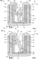
- Fig. 5 is a vertical sectional view of a rotary-segment electromechanical system 200 according to a further exemplary embodiment of the present invention which combines the reluctance-boost geometry in both poles with the auxiliary permanent magnet 195 provided in one of the pole members.
- the electromechanical system 200 mainly differs from the electromechanical system 100 described with reference to Figs. 1 - 4 in that the magnetic system includes a second pole member 160' with a second end portion 162' on which a permanent magnet 195 is arranged. In this configuration, the second end portion 162' also includes a step recess 164'. As shown in Fig.
- the step recess 164' includes a curved segment 166' similar to the curved segment 166 of the reluctance-boost recess of the previous embodiment of Figs. 1 - 4 , which protrudes away from a front face of the permanent magnet 195 which is arranged in an additional cavity provided in the second end portion 162.
- the permanent magnet 195 is magnetically polarized with respect to the lower lobe 172 of the rotating member and the direction of the magnetic flux lines across the second coil 120 so as to enhance the attractive magnetic force applied onto the lower lobe 172, and therefore, increase the torque of the rotation member 170 in the counter-clockwise direction.
- the other features of the second pole member 160' are similar or identical to those described above with reference to the second pole member 160.
- the electromechanical system 200 shown in Fig. 5 are also identical or similar to those of the electromechanical system 100 described above. Namely, the electromechanical system 200 maintains the first pole member 150 with the step recess 154 having the specific reluctance-boost contour described in the previous embodiment. Therefore, a full description of the identical elements will be omitted for the present embodiment.
- auxiliary permanent magnet 195 may be implemented by discarding the reluctance-boost geometry on one of the pole members on which the permanent magnet is installed, as in the exemplary embodiment described below with reference to Figs. 7 - 8 .
- the permanent magnet 195 may be provided in the first end portion 162 of the second pole member 160 (instead of the second pole member 160' shown in Fig. 5 ) by modifying the step recess 154 to accommodate the permanent magnet 195 while maintaining the curved segment 156 responsible for achieving the reluctance-boost effect.
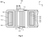
- the electromechanical system 300 mainly differs from the electromechanical system 100 described with reference to Figs. 1 - 4 in that the magnetic system includes a second pole member 160" with a second end portion 162" on which the permanent magnet 195 is arranged.
- the second end portion 162" is simply provided with a cavity or standard step recess 164" in which the permanent magnet 195 is arranged, i.e. without a curved side wall protruding away from a front face of the permanent magnet 195 such as in the electromechanical system 200 described with reference to Figs. 5 and 6 .
- the permanent magnet 195 is also oriented with a magnetically polarity that enhances the attractive magnetic force applied onto the lower lobe 172, and therefore, increase the torque of the rotation member 170 in the counter-clockwise direction.
- the other features of the second pole member 160" are similar or identical to those described above with reference to the second pole member 160.
- the rotary-segment electromechanical systems according to the principles of the present invention described above may be advantageously used for operating contact systems of electrical switching devices, such as DC power relay, with a direct rotating motion that is limited by a rotation angle of a predetermined angle, preferably up to 45°, while using a minimum of moving parts, thereby offering a design of higher robustness than conventional rotary electromechanical systems
Landscapes
- Physics & Mathematics (AREA)
- Electromagnetism (AREA)
- Engineering & Computer Science (AREA)
- Power Engineering (AREA)
- Linear Motors (AREA)
- Electromagnets (AREA)
- Reciprocating, Oscillating Or Vibrating Motors (AREA)
Claims (14)
- Système électromécanique à segment rotatif pour un dispositif de commutation électrique, le système électromécanique comprenant :un assemblage de bobine de charge électrique (100) incluant une première bobine (110) et une deuxième bobine (120) qui sont adaptées pour générer des champs magnétiques respectifs en réaction à des courants de charge électrique respectifs, dans lequel la première bobine (110) et la deuxième bobine (120) sont alignées sur l'axe de bobine respectif parallèlement l'une à l'autre et disposées espacées l'une de l'autre dans une direction transversale aux axes de bobines par une zone d'espacement (130) ;un système magnétique adapté pour fournir un trajet de flux magnétique pour transmettre des lignes de flux magnétique du champ magnétique généré par l'assemblage de bobine de charge électrique (100),par lequelle système magnétique incluant :un premier élément de pôle (150) disposé sur un côté supérieur de la première bobine (110) et un deuxième élément de pôle (160) disposé sur un côté supérieur de la deuxième bobine (120),chacun des premier et deuxième éléments de pôle (150, 160) présentant des premières parties d'extrémité respectives (152, 162) disposées hors de la première bobine (110) et de la deuxième bobine (120), respectivement, chacune des premières parties d'extrémité (152, 162) s'étendant vers le bas dans la zone d'espacement (130) parallèlement l'une à l'autre et vers le premier axe de bobine ; etun élément rotatif (170) disposé dans la zone d'espacement (130) et entre les premières parties d'extrémité (152, 162) des premier et deuxième éléments de pôle (150, 160), l'élément rotatif (170) présentant des premier et deuxième lobes (174, 172) adaptés pour exécuter un mouvement de rotation autour d'un axe central aligné sur l'intersection d'un plan parallèle aux premières parties d'extrémité (152, 162) avec un plan transversal au premier axe de bobine,dans lequel le premier lobe (174) et le deuxième lobe (172) sont disposés diamétralement opposés l'un à l'autre par rapport à une zone centrale (176) de l'élément rotatif (170), le premier lobe (174) présentant une face d'extrémité orientée vers la première partie d'extrémité (152) du premier élément de pôle (150) et le deuxième lobe (124) présentant une face d'extrémité orientée vers la deuxième partie d'extrémité (162) du deuxième élément de pôle (160) ;dans lequel les premières parties d'extrémité (152, 162) des premier et deuxième éléments de pôle (150, 160) sont configurées pour diriger des lignes de champ magnétique générées par les première et deuxième bobines (110, 120) vers les premier et deuxième lobes de l'élément rotatif (170), respectivement, pour produire une force magnétique résultante qui fait exécuter aux premier et deuxième lobes (174, 172) le mouvement de rotation vers les premier et deuxième éléments de pôle respectifs (150, 160) sur mise sous tension de l'assemblage de bobine de charge électrique (100) ;dans lequel l'au moins une des premières parties d'extrémité (152, 162) des premier et deuxième éléments de pôle (150, 160) et la face d'extrémité du lobe (174, 172) de l'élément rotatif (170) orientée vers ladite au moins une première partie d'extrémité (152, 162) sont conçues avec des contours de forme correspondants qui présentent une géométrie adaptée pour diminuer une réluctance lorsque ledit lobe entre en contact avec la première partie d'extrémité au cours du mouvement de rotation de l'élément rotatif (170),caractérisé en ce quela géométrie du contour de forme correspondant du lobe (174) orienté vers l'au moins une première partie d'extrémité (152, 162) présente une paroi latérale incurvée complémentaire (175) sur une face d'extrémité dudit lobe (174) de sorte que le contact par chevauchement entre ledit lobe (174) et la première partie d'extrémité respective (152) est graduellement augmenté au cours d'une rotation de l'élément rotatif (170) jusqu'à ce que le mouvement de rotation s'arrête sur un angle de rotation prédéterminé.
- Le système électromécanique selon la revendication 1, dans lequel
le contour de forme de l'au moins une première partie d'extrémité présente la forme d'une cavité étagée avec la paroi latérale incurvée qui est définie par un segment circulaire d'une longueur donnée sur un plan transversal à l'axe central. - Le système électromécanique selon la revendication 2, dans lequelle mouvement de rotation est arrêté sur un angle de rotation prédéterminé qui constitue un angle maximal de rotation sur lequel intervient un contact par chevauchement complet entre les contours de forme correspondants du lobe orienté et la première partie d'extrémité ; et/oula longueur et le rayon du segment circulaire du contour de forme sont adaptés pour limiter le mouvement de rotation exécuté par l'élément rotatif à un angle maximal de rotation inférieur ou égal à 45 °.
- Le système électromécanique selon l'une quelconque des revendications 1 à 3, dans lequel le système magnétique comprend en outre :un aimant permanent (195) disposé sur au moins une des premières parties d'extrémité (152, 162) des premier et deuxième éléments de pôle (150, 160),dans lequel l'aimant permanent (195) est disposé orienté vers le lobe respectif de l'élément rotatif (170) et est polarisé magnétiquement pour diminuer une réluctance sur un écart de séparation entre la première partie d'extrémité sur laquelle il est disposé et le lobe qui fait face.
- Le système électromécanique selon la revendication 4, dans lequel :ledit contour de forme est disposé dans uniquement une des premières parties des premier et deuxième éléments de pôle (150, 160), etl'aimant permanent (195) est disposé sur l'autre des premières parties des premier et deuxième éléments de pôle (150, 160).
- Le système électromécanique selon l'une quelconque des revendications 1 à 5, dans lequell'élément rotatif est adapté pour adopter un état ouvert qui constitue une orientation de rotation sur laquelle les premier et deuxième lobes (174, 172) sont respectivement séparés des premières parties d'extrémité (152, 164) des premier et deuxième éléments de pôle (150, 160) par des écarts de séparation maximale respectifs lorsque l'assemblage de bobine de charge électrique n'est pas sous tension ; et/oul'élément rotatif (170) est adapté pour tourner selon un angle de rotation prédéterminé jusqu'à un état fermé lorsque l'assemblage de bobine de charge électrique (100) est mis sous tension par un courant de charge électrique donné,dans lequel dans l'état fermé au moins un des premier et deuxième lobes (174, 172) de l'élément rotatif (170) s'adosse complètement contre la première partie d'extrémité qui fait face (152, 162) des premier et deuxième éléments de pôle respectifs (150, 160).
- Le système électromécanique selon la revendication 1, dans lequel
ledit angle de rotation prédéterminé est inférieur ou égal à 45 °. - Le système électromécanique selon l'une quelconque des revendications 1 à 7, dans lequel
les premier et deuxième éléments de pôle (150, 160) présentent des deuxièmes parties d'extrémité respectives qui pénètrent depuis le côté supérieur des première et deuxième bobines respectives (110, 120) dans un espace intérieur des première et deuxième bobines respectives (110, 120). - Le système électromécanique selon l'une quelconque des revendications 1 à 8, dans lequel
au moins un des premier et deuxième éléments de pôle (150, 160) présente une forme de U disposée avec les montants vers le bas par rapport au côté supérieur des première et deuxième bobines (110, 120), le montant comprenant la première partie d'extrémité s'étendant hors des première et deuxième bobines (110, 120). - Le système électromécanique selon l'une quelconque des revendications 1 à 9, dans lequel le système magnétique comprend en outre :un noyau principal (180) disposé sur un côté inférieur des première et deuxième bobines (110, 120) et configuré pour connecter le premier élément de pôle (150) au deuxième élément de pôle (160),dans lequel le noyau principal (180), le premier élément de pôle (150), l'élément rotatif (170) et le deuxième élément de pôle (160) forment ledit trajet de flux magnétique fourni par le système magnétique.
- Le système électromécanique selon la revendication 10, dans lequelle noyau principal (180) présente une forme de U constituée par une zone centrale et une paire de premier et deuxième montants qui s'étendent vers le haut depuis des côtés respectifs de ladite zone centrale,dans lequel le premier montant pénètre à travers l'espace intérieur de la première bobine (110) et le deuxième montant pénètre à travers l'espace intérieur de la deuxième bobine, depuis le côté inférieur des première et deuxième bobines (110, 120), s'étendant vers le haut jusqu'à entrer en contact avec les deuxièmes parties d'extrémité respectives des premier et deuxième éléments de pôle (150, 160).
- Le système électromécanique rotatif selon la revendication 10 ou 11, dans lequel le système magnétique comprend en outre :un noyau auxiliaire (190) adapté pour augmenter le confinement des lignes de flux magnétique à l'intérieur de l'espace intérieur des première et deuxième bobines (110, 120),dans lequel le noyau auxiliaire (190) est adapté pour s'étendre sur la longueur axiale des première et deuxième bobines (110, 120) et un côté intérieur du noyau principal (180) ;dans lequel le noyau principal (180) et/ou le noyau auxiliaire (190) peuvent être constitués comme une pièce unique ou une pluralité de pièces couplées magnétiquement l'une à l'autre ; et/oudans lequel le noyau principal (180) et/ou le noyau auxiliaire (190) sont constitués de fer doux, sous forme pleine ou stratifiée ; et/oudans lequel l'élément rotatif (170) est constitué de fer doux.
- Dispositif de commutation électrique, comprenant :
un système électromécanique à segment rotatif selon l'une quelconque des revendications 1 à 12. - Le dispositif de commutation électrique de la revendication 13, dans lequel le dispositif de commutation électrique est un contacteur ou un relai.
Priority Applications (4)
| Application Number | Priority Date | Filing Date | Title |
|---|---|---|---|
| EP22186400.2A EP4310880B1 (fr) | 2022-07-22 | 2022-07-22 | Système électromécanique à segment rotatif avec augmentation de la résistance |
| JP2023117184A JP2024014795A (ja) | 2022-07-22 | 2023-07-19 | リラクタンスブーストによる回転セグメント電気機械システム |
| CN202310899111.XA CN117438253A (zh) | 2022-07-22 | 2023-07-20 | 具有磁阻提升的旋转部段机电系统 |
| US18/355,439 US20240029983A1 (en) | 2022-07-22 | 2023-07-20 | Rotary-Segment Electromechanical System with Reluctance Boost |
Applications Claiming Priority (1)
| Application Number | Priority Date | Filing Date | Title |
|---|---|---|---|
| EP22186400.2A EP4310880B1 (fr) | 2022-07-22 | 2022-07-22 | Système électromécanique à segment rotatif avec augmentation de la résistance |
Publications (2)
| Publication Number | Publication Date |
|---|---|
| EP4310880A1 EP4310880A1 (fr) | 2024-01-24 |
| EP4310880B1 true EP4310880B1 (fr) | 2025-05-28 |
Family
ID=82701924
Family Applications (1)
| Application Number | Title | Priority Date | Filing Date |
|---|---|---|---|
| EP22186400.2A Active EP4310880B1 (fr) | 2022-07-22 | 2022-07-22 | Système électromécanique à segment rotatif avec augmentation de la résistance |
Country Status (4)
| Country | Link |
|---|---|
| US (1) | US20240029983A1 (fr) |
| EP (1) | EP4310880B1 (fr) |
| JP (1) | JP2024014795A (fr) |
| CN (1) | CN117438253A (fr) |
Family Cites Families (8)
| Publication number | Priority date | Publication date | Assignee | Title |
|---|---|---|---|---|
| US4329672A (en) * | 1977-01-29 | 1982-05-11 | Elektro-Mechanik Gmbh | Polarized electromagnetic drive for a limited operating range of a control element |
| FR2793944B1 (fr) * | 1999-05-20 | 2001-07-13 | Schneider Electric Ind Sa | Dispositif de commande d'ouverture et/ou de fermeture, en particulier pour un appareil de coupure tel un disjoncteur, et disjoncteur equipe d'un tel dispositif |
| DE102004002528A1 (de) * | 2004-01-12 | 2005-08-04 | Siemens Ag | Elektromagnetischer Linearantrieb |
| JP4446066B2 (ja) * | 2004-06-17 | 2010-04-07 | 新電元メカトロニクス株式会社 | ロータリソレノイド |
| FR2873232B1 (fr) * | 2004-07-16 | 2008-10-03 | Peugeot Citroen Automobiles Sa | Dispositif de commande electromagnetique fonctionnant en basculement |
| CN109103052B (zh) | 2017-06-21 | 2024-05-14 | 泰科电子(深圳)有限公司 | 电磁系统 |
| GB2571741B (en) * | 2018-03-07 | 2022-03-23 | Sentec Ltd | Electricity meter with electrically-controlled electromechanical switch |
| JP7263714B2 (ja) * | 2018-08-24 | 2023-04-25 | オムロン株式会社 | 電磁継電器 |
-
2022
- 2022-07-22 EP EP22186400.2A patent/EP4310880B1/fr active Active
-
2023
- 2023-07-19 JP JP2023117184A patent/JP2024014795A/ja active Pending
- 2023-07-20 US US18/355,439 patent/US20240029983A1/en active Pending
- 2023-07-20 CN CN202310899111.XA patent/CN117438253A/zh active Pending
Also Published As
| Publication number | Publication date |
|---|---|
| EP4310880A1 (fr) | 2024-01-24 |
| US20240029983A1 (en) | 2024-01-25 |
| JP2024014795A (ja) | 2024-02-01 |
| CN117438253A (zh) | 2024-01-23 |
Similar Documents
| Publication | Publication Date | Title |
|---|---|---|
| JP5735564B2 (ja) | 素早く作動する双安定分極電磁アクチュエータ | |
| US6422533B1 (en) | High force solenoid valve and method of improved solenoid valve performance | |
| US7843293B1 (en) | Bistable magnetic drive for a switch | |
| CN101393822B (zh) | 电磁促动器和装备有这种电磁促动器的开关设备 | |
| US6009615A (en) | Method of manufacturing a bistable magnetic actuator | |
| RS56806B1 (sr) | Bistabilni elektromagnetni relej kod x-pogonskog motora | |
| US4451808A (en) | Electromagnet equipped with a moving system including a permanent magnet and designed for monostable operation | |
| JPH0797531B2 (ja) | 双安定分極電磁石 | |
| US9214267B2 (en) | Electromagnetic actuator device | |
| US6674349B1 (en) | Opening and/or closing control device, in particular for a switchgear apparatus such as a circuit breaker, and circuit breaker equipped with such a device | |
| US4609899A (en) | Polarized electromagnet having three states and a control circuit for said electromagnet | |
| EP4310880B1 (fr) | Système électromécanique à segment rotatif avec augmentation de la résistance | |
| EP2859571B1 (fr) | Appareil de commutation électrique et relais comprenant une armature ferromagnétique ou magnétique ayant une partie effilée | |
| JPH0344010A (ja) | 電磁作動式アクチュエータ | |
| US7135947B2 (en) | Hybrid microwave T-switch actuator | |
| JP3280536B2 (ja) | アクチュエータ | |
| JP2006512039A (ja) | 永久磁石を具備した二重コイル付きの電磁バルブアクチュエータ | |
| CN109595382B (zh) | 一种控制滑动凸轮位移的多执行器电磁阀 | |
| JP4515664B2 (ja) | 電力用開閉装置の操作装置 | |
| EP2197012B1 (fr) | Électroaimant pour contacteur électrique | |
| RU121642U1 (ru) | Бистабильный электромагнит привода коммутационного устройства | |
| JP2003016888A (ja) | 電力用開閉装置の操作装置 | |
| JP2754296B2 (ja) | ロータリアクチュエータ | |
| RU121641U1 (ru) | Бистабильный электромагнит привода коммутационного устройства | |
| JPH0119372Y2 (fr) |
Legal Events
| Date | Code | Title | Description |
|---|---|---|---|
| PUAI | Public reference made under article 153(3) epc to a published international application that has entered the european phase |
Free format text: ORIGINAL CODE: 0009012 |
|
| STAA | Information on the status of an ep patent application or granted ep patent |
Free format text: STATUS: THE APPLICATION HAS BEEN PUBLISHED |
|
| AK | Designated contracting states |
Kind code of ref document: A1 Designated state(s): AL AT BE BG CH CY CZ DE DK EE ES FI FR GB GR HR HU IE IS IT LI LT LU LV MC MK MT NL NO PL PT RO RS SE SI SK SM TR |
|
| STAA | Information on the status of an ep patent application or granted ep patent |
Free format text: STATUS: REQUEST FOR EXAMINATION WAS MADE |
|
| 17P | Request for examination filed |
Effective date: 20240722 |
|
| RBV | Designated contracting states (corrected) |
Designated state(s): AL AT BE BG CH CY CZ DE DK EE ES FI FR GB GR HR HU IE IS IT LI LT LU LV MC MK MT NL NO PL PT RO RS SE SI SK SM TR |
|
| GRAP | Despatch of communication of intention to grant a patent |
Free format text: ORIGINAL CODE: EPIDOSNIGR1 |
|
| STAA | Information on the status of an ep patent application or granted ep patent |
Free format text: STATUS: GRANT OF PATENT IS INTENDED |
|
| INTG | Intention to grant announced |
Effective date: 20250203 |
|
| GRAS | Grant fee paid |
Free format text: ORIGINAL CODE: EPIDOSNIGR3 |
|
| GRAA | (expected) grant |
Free format text: ORIGINAL CODE: 0009210 |
|
| STAA | Information on the status of an ep patent application or granted ep patent |
Free format text: STATUS: THE PATENT HAS BEEN GRANTED |
|
| AK | Designated contracting states |
Kind code of ref document: B1 Designated state(s): AL AT BE BG CH CY CZ DE DK EE ES FI FR GB GR HR HU IE IS IT LI LT LU LV MC MK MT NL NO PL PT RO RS SE SI SK SM TR |
|
| REG | Reference to a national code |
Ref country code: GB Ref legal event code: FG4D |
|
| REG | Reference to a national code |
Ref country code: CH Ref legal event code: EP |
|
| REG | Reference to a national code |
Ref country code: IE Ref legal event code: FG4D Ref country code: DE Ref legal event code: R096 Ref document number: 602022015144 Country of ref document: DE |
|
| PGFP | Annual fee paid to national office [announced via postgrant information from national office to epo] |
Ref country code: FR Payment date: 20250610 Year of fee payment: 4 |
|
| REG | Reference to a national code |
Ref country code: NL Ref legal event code: MP Effective date: 20250528 |
|
| PG25 | Lapsed in a contracting state [announced via postgrant information from national office to epo] |
Ref country code: ES Free format text: LAPSE BECAUSE OF FAILURE TO SUBMIT A TRANSLATION OF THE DESCRIPTION OR TO PAY THE FEE WITHIN THE PRESCRIBED TIME-LIMIT Effective date: 20250528 Ref country code: FI Free format text: LAPSE BECAUSE OF FAILURE TO SUBMIT A TRANSLATION OF THE DESCRIPTION OR TO PAY THE FEE WITHIN THE PRESCRIBED TIME-LIMIT Effective date: 20250528 |
|
| PGFP | Annual fee paid to national office [announced via postgrant information from national office to epo] |
Ref country code: DE Payment date: 20250604 Year of fee payment: 4 |
|
| REG | Reference to a national code |
Ref country code: LT Ref legal event code: MG9D |
|
| PG25 | Lapsed in a contracting state [announced via postgrant information from national office to epo] |
Ref country code: NO Free format text: LAPSE BECAUSE OF FAILURE TO SUBMIT A TRANSLATION OF THE DESCRIPTION OR TO PAY THE FEE WITHIN THE PRESCRIBED TIME-LIMIT Effective date: 20250828 Ref country code: GR Free format text: LAPSE BECAUSE OF FAILURE TO SUBMIT A TRANSLATION OF THE DESCRIPTION OR TO PAY THE FEE WITHIN THE PRESCRIBED TIME-LIMIT Effective date: 20250829 |
|
| PG25 | Lapsed in a contracting state [announced via postgrant information from national office to epo] |
Ref country code: NL Free format text: LAPSE BECAUSE OF FAILURE TO SUBMIT A TRANSLATION OF THE DESCRIPTION OR TO PAY THE FEE WITHIN THE PRESCRIBED TIME-LIMIT Effective date: 20250528 Ref country code: PL Free format text: LAPSE BECAUSE OF FAILURE TO SUBMIT A TRANSLATION OF THE DESCRIPTION OR TO PAY THE FEE WITHIN THE PRESCRIBED TIME-LIMIT Effective date: 20250528 |
|
| PG25 | Lapsed in a contracting state [announced via postgrant information from national office to epo] |
Ref country code: BG Free format text: LAPSE BECAUSE OF FAILURE TO SUBMIT A TRANSLATION OF THE DESCRIPTION OR TO PAY THE FEE WITHIN THE PRESCRIBED TIME-LIMIT Effective date: 20250528 |
|
| PG25 | Lapsed in a contracting state [announced via postgrant information from national office to epo] |
Ref country code: HR Free format text: LAPSE BECAUSE OF FAILURE TO SUBMIT A TRANSLATION OF THE DESCRIPTION OR TO PAY THE FEE WITHIN THE PRESCRIBED TIME-LIMIT Effective date: 20250528 |
|
| PGFP | Annual fee paid to national office [announced via postgrant information from national office to epo] |
Ref country code: AT Payment date: 20251020 Year of fee payment: 4 |
|
| PG25 | Lapsed in a contracting state [announced via postgrant information from national office to epo] |
Ref country code: RS Free format text: LAPSE BECAUSE OF FAILURE TO SUBMIT A TRANSLATION OF THE DESCRIPTION OR TO PAY THE FEE WITHIN THE PRESCRIBED TIME-LIMIT Effective date: 20250828 |
|
| PG25 | Lapsed in a contracting state [announced via postgrant information from national office to epo] |
Ref country code: IS Free format text: LAPSE BECAUSE OF FAILURE TO SUBMIT A TRANSLATION OF THE DESCRIPTION OR TO PAY THE FEE WITHIN THE PRESCRIBED TIME-LIMIT Effective date: 20250928 |
|
| PG25 | Lapsed in a contracting state [announced via postgrant information from national office to epo] |
Ref country code: LV Free format text: LAPSE BECAUSE OF FAILURE TO SUBMIT A TRANSLATION OF THE DESCRIPTION OR TO PAY THE FEE WITHIN THE PRESCRIBED TIME-LIMIT Effective date: 20250528 |
|
| REG | Reference to a national code |
Ref country code: AT Ref legal event code: MK05 Ref document number: 1799131 Country of ref document: AT Kind code of ref document: T Effective date: 20250528 |
|
| PG25 | Lapsed in a contracting state [announced via postgrant information from national office to epo] |
Ref country code: AT Free format text: LAPSE BECAUSE OF FAILURE TO SUBMIT A TRANSLATION OF THE DESCRIPTION OR TO PAY THE FEE WITHIN THE PRESCRIBED TIME-LIMIT Effective date: 20250528 Ref country code: DK Free format text: LAPSE BECAUSE OF FAILURE TO SUBMIT A TRANSLATION OF THE DESCRIPTION OR TO PAY THE FEE WITHIN THE PRESCRIBED TIME-LIMIT Effective date: 20250528 Ref country code: SM Free format text: LAPSE BECAUSE OF FAILURE TO SUBMIT A TRANSLATION OF THE DESCRIPTION OR TO PAY THE FEE WITHIN THE PRESCRIBED TIME-LIMIT Effective date: 20250528 |
|
| PG25 | Lapsed in a contracting state [announced via postgrant information from national office to epo] |
Ref country code: CZ Free format text: LAPSE BECAUSE OF FAILURE TO SUBMIT A TRANSLATION OF THE DESCRIPTION OR TO PAY THE FEE WITHIN THE PRESCRIBED TIME-LIMIT Effective date: 20250528 |
|
| PG25 | Lapsed in a contracting state [announced via postgrant information from national office to epo] |
Ref country code: EE Free format text: LAPSE BECAUSE OF FAILURE TO SUBMIT A TRANSLATION OF THE DESCRIPTION OR TO PAY THE FEE WITHIN THE PRESCRIBED TIME-LIMIT Effective date: 20250528 |
|
| PG25 | Lapsed in a contracting state [announced via postgrant information from national office to epo] |
Ref country code: SK Free format text: LAPSE BECAUSE OF FAILURE TO SUBMIT A TRANSLATION OF THE DESCRIPTION OR TO PAY THE FEE WITHIN THE PRESCRIBED TIME-LIMIT Effective date: 20250528 |
|
| PG25 | Lapsed in a contracting state [announced via postgrant information from national office to epo] |
Ref country code: IT Free format text: LAPSE BECAUSE OF FAILURE TO SUBMIT A TRANSLATION OF THE DESCRIPTION OR TO PAY THE FEE WITHIN THE PRESCRIBED TIME-LIMIT Effective date: 20250528 |
|
| REG | Reference to a national code |
Ref country code: CH Ref legal event code: H13 Free format text: ST27 STATUS EVENT CODE: U-0-0-H10-H13 (AS PROVIDED BY THE NATIONAL OFFICE) Effective date: 20260224 |
|
| REG | Reference to a national code |
Ref country code: DE Ref legal event code: R097 Ref document number: 602022015144 Country of ref document: DE |
|
| PG25 | Lapsed in a contracting state [announced via postgrant information from national office to epo] |
Ref country code: LU Free format text: LAPSE BECAUSE OF NON-PAYMENT OF DUE FEES Effective date: 20250722 Ref country code: RO Free format text: LAPSE BECAUSE OF FAILURE TO SUBMIT A TRANSLATION OF THE DESCRIPTION OR TO PAY THE FEE WITHIN THE PRESCRIBED TIME-LIMIT Effective date: 20250528 |
|
| REG | Reference to a national code |
Ref country code: BE Ref legal event code: MM Effective date: 20250731 |
|
| PLBE | No opposition filed within time limit |
Free format text: ORIGINAL CODE: 0009261 |
|
| STAA | Information on the status of an ep patent application or granted ep patent |
Free format text: STATUS: NO OPPOSITION FILED WITHIN TIME LIMIT |
|
| REG | Reference to a national code |
Ref country code: CH Ref legal event code: L10 Free format text: ST27 STATUS EVENT CODE: U-0-0-L10-L00 (AS PROVIDED BY THE NATIONAL OFFICE) Effective date: 20260409 |
|
| PG25 | Lapsed in a contracting state [announced via postgrant information from national office to epo] |
Ref country code: BE Free format text: LAPSE BECAUSE OF NON-PAYMENT OF DUE FEES Effective date: 20250731 |