EP4311968A1 - Thermisch isoliertes leitungselement und durch die montage einer vielzahl solcher leitungselemente erhaltenes lufttransportnetz - Google Patents
Thermisch isoliertes leitungselement und durch die montage einer vielzahl solcher leitungselemente erhaltenes lufttransportnetz Download PDFInfo
- Publication number
- EP4311968A1 EP4311968A1 EP23187935.4A EP23187935A EP4311968A1 EP 4311968 A1 EP4311968 A1 EP 4311968A1 EP 23187935 A EP23187935 A EP 23187935A EP 4311968 A1 EP4311968 A1 EP 4311968A1
- Authority
- EP
- European Patent Office
- Prior art keywords
- tube
- spacer
- annular
- conduit
- conduit element
- Prior art date
- Legal status (The legal status is an assumption and is not a legal conclusion. Google has not performed a legal analysis and makes no representation as to the accuracy of the status listed.)
- Granted
Links
Images

Classifications
-
- F—MECHANICAL ENGINEERING; LIGHTING; HEATING; WEAPONS; BLASTING
- F16—ENGINEERING ELEMENTS AND UNITS; GENERAL MEASURES FOR PRODUCING AND MAINTAINING EFFECTIVE FUNCTIONING OF MACHINES OR INSTALLATIONS; THERMAL INSULATION IN GENERAL
- F16L—PIPES; JOINTS OR FITTINGS FOR PIPES; SUPPORTS FOR PIPES, CABLES OR PROTECTIVE TUBING; MEANS FOR THERMAL INSULATION IN GENERAL
- F16L59/00—Thermal insulation in general
- F16L59/06—Arrangements using an air layer or vacuum
-
- F—MECHANICAL ENGINEERING; LIGHTING; HEATING; WEAPONS; BLASTING
- F16—ENGINEERING ELEMENTS AND UNITS; GENERAL MEASURES FOR PRODUCING AND MAINTAINING EFFECTIVE FUNCTIONING OF MACHINES OR INSTALLATIONS; THERMAL INSULATION IN GENERAL
- F16L—PIPES; JOINTS OR FITTINGS FOR PIPES; SUPPORTS FOR PIPES, CABLES OR PROTECTIVE TUBING; MEANS FOR THERMAL INSULATION IN GENERAL
- F16L59/00—Thermal insulation in general
- F16L59/04—Arrangements using dry fillers, e.g. using slag wool
-
- F—MECHANICAL ENGINEERING; LIGHTING; HEATING; WEAPONS; BLASTING
- F16—ENGINEERING ELEMENTS AND UNITS; GENERAL MEASURES FOR PRODUCING AND MAINTAINING EFFECTIVE FUNCTIONING OF MACHINES OR INSTALLATIONS; THERMAL INSULATION IN GENERAL
- F16L—PIPES; JOINTS OR FITTINGS FOR PIPES; SUPPORTS FOR PIPES, CABLES OR PROTECTIVE TUBING; MEANS FOR THERMAL INSULATION IN GENERAL
- F16L59/00—Thermal insulation in general
- F16L59/14—Arrangements for the insulation of pipes or pipe systems
- F16L59/143—Pre-insulated pipes
-
- F—MECHANICAL ENGINEERING; LIGHTING; HEATING; WEAPONS; BLASTING
- F16—ENGINEERING ELEMENTS AND UNITS; GENERAL MEASURES FOR PRODUCING AND MAINTAINING EFFECTIVE FUNCTIONING OF MACHINES OR INSTALLATIONS; THERMAL INSULATION IN GENERAL
- F16L—PIPES; JOINTS OR FITTINGS FOR PIPES; SUPPORTS FOR PIPES, CABLES OR PROTECTIVE TUBING; MEANS FOR THERMAL INSULATION IN GENERAL
- F16L9/00—Rigid pipes
- F16L9/18—Double-walled pipes; Multi-channel pipes or pipe assemblies
-
- F—MECHANICAL ENGINEERING; LIGHTING; HEATING; WEAPONS; BLASTING
- F24—HEATING; RANGES; VENTILATING
- F24F—AIR-CONDITIONING; AIR-HUMIDIFICATION; VENTILATION; USE OF AIR CURRENTS FOR SCREENING
- F24F13/00—Details common to, or for air-conditioning, air-humidification, ventilation or use of air currents for screening
- F24F13/02—Ducting arrangements
- F24F13/0209—Ducting arrangements characterised by their connecting means, e.g. flanges
-
- F—MECHANICAL ENGINEERING; LIGHTING; HEATING; WEAPONS; BLASTING
- F24—HEATING; RANGES; VENTILATING
- F24F—AIR-CONDITIONING; AIR-HUMIDIFICATION; VENTILATION; USE OF AIR CURRENTS FOR SCREENING
- F24F13/00—Details common to, or for air-conditioning, air-humidification, ventilation or use of air currents for screening
- F24F13/02—Ducting arrangements
- F24F13/0245—Manufacturing or assembly of air ducts; Methods therefor
-
- F—MECHANICAL ENGINEERING; LIGHTING; HEATING; WEAPONS; BLASTING
- F24—HEATING; RANGES; VENTILATING
- F24F—AIR-CONDITIONING; AIR-HUMIDIFICATION; VENTILATION; USE OF AIR CURRENTS FOR SCREENING
- F24F13/00—Details common to, or for air-conditioning, air-humidification, ventilation or use of air currents for screening
- F24F13/02—Ducting arrangements
- F24F13/0263—Insulation for air ducts
-
- F—MECHANICAL ENGINEERING; LIGHTING; HEATING; WEAPONS; BLASTING
- F24—HEATING; RANGES; VENTILATING
- F24F—AIR-CONDITIONING; AIR-HUMIDIFICATION; VENTILATION; USE OF AIR CURRENTS FOR SCREENING
- F24F13/00—Details common to, or for air-conditioning, air-humidification, ventilation or use of air currents for screening
- F24F13/02—Ducting arrangements
- F24F13/0281—Multilayer duct
Definitions
- the present invention relates to the technical field of air management and distribution installations in a building.
- It relates more particularly to a thermally insulated duct element, suitable for creating an air transport network in such air management and distribution installations in a building.
- Air management and distribution installations in buildings for example ventilation installations of the VMC type with single or double flow, or any other air treatment equipment, include motorized fans for insufflation and/or the extraction of air, which can be associated with a network of ducts or pipes for the transport of this air.
- Flexible or rigid ducts, of the single-wall type or with thermal insulation, can be used.
- the annular spacer systems provided at the two ends of the conduit element ensure the concentric, spaced maintenance of the two inner and outer tubes.
- annular spacer systems fill the annular space between the inner tube 2 and the outer tube 3; they partition an annular volume of air (or other thermal insulation) which limits calorie losses. They preferably have a solid structure, without openings, but they may have small openings, orifices or slots, or be porous.
- thermal insulating material a material having an average thermal conduction coefficient less than or equal to 0.05 W/(m.K).
- the present invention also relates to an air transport network comprising a plurality of thermally insulated duct elements as defined above, and assembled to each other by assembly means.
- said assembly means are of the male-female interlocking type, said conduit elements comprising a first male-type interlocking end and a second female-type interlocking end.
- said assembly means are of the male-female interlocking type, said conduit elements comprising two female-type interlocking ends, and said air transport network further comprising a system of connectors Male-male type interlocking.
- Such a structure also allows control of airtightness, particularly at the level of each junction or connection to other components (box, vents, distributor, etc.).
- conduit element and “thermally insulated conduit element” are synonymous and used interchangeably.
- thermally insulated duct elements described below are intended to be assembled with other identical or similar duct elements to create an air transport network, in particular a single or double flow VMC network in an installation management and distribution of air in a building.
- the two tubes 2 and 3 here have a circular section.
- this section can be oval, oblong or polygonal.
- the two tubes 2 and 3 here have the same length or practically the same length.
- the outer tube 3 is concentric with the inner tube 2, kept separated from the latter by systems of annular spacers 4.
- At least two of these annular spacer systems 4 are arranged at the ends 23, 33 of the inner tube 2 and the outer tube 3, between their facing surfaces 22 and 31.
- One or more complementary annular spacer systems 4 can be provided between the two end annular spacer systems 4a.
- the central core defined by the interior surface 21 of the interior tube 2 is intended for the transport of air, and the annular spacer systems 4 make it possible to create an annular space 5 between the two tubes 2 and 3 to obtain a tubular wall thermally insulated.
- the annular space 5 in question has a thickness between 5 and 25 mm, and more preferably between 10 and 20 mm.
- the annular spacer systems 4 are made of a thermal insulating material and they are solid, that is to say without openings, to define between them at least one section of closed annular space 5a.
- the inner 2 and outer 3 tubes preferably have a certain rigidity to maintain their cylindrical shape, or other, over their entire length, without deforming, or without deforming too much, under the effect of external stresses.
- These two inner 2 and outer 3 tubes can be of various nature depending on the applications envisaged: metal, plastic, composite, cardboard, technical paper, fiber fabric, rigid foam etc.
- the length of the thermally insulated conduit element 1 can for example be between 1m and 2m.
- the annular spacer systems 4 are made of an airtight or practically airtight material.
- the material used is preferably airtight, but we can also consider the use of an air-porous material, allowing air exchange on both sides, as long as this porosity does not allow the creation of an air flow.
- the annular spacer systems 4 each consist of a single ring of material a few centimeters in length and with a thickness of between 5 and 25 mm, and preferably between 10 and 20 mm.
- Each ring of material 4 has the general shape of a portion of a tube and comprises: an outer ring 41, bearing against the inner surface 31 of the outer tube 3, an inner ring 42, bearing against the outer surface 22 of the inner tube 2, an external face 43, oriented towards the outside, and an internal face 44, opposite, oriented towards the inside.
- At least some of the surfaces 41, 42 of the annular spacer systems 4 in contact with the inner 2 and outer 3 tubes may comprise structures of grooves or protuberances adapted to limit the possibilities of separation between said spacer systems 4 and said inner tubes 2 and outer tubes 3.
- the annular spacer systems 4 are advantageously made of a compressible material. Their structure can be “full”, formed from a juxtaposition of closed cells.
- polystyrene foams can be made of a material chosen from crosslinked polyolefin foams, in particular expanded polypropylene (PPE) or expanded polyethylene (PEE) foams, or any other insulation made from compressed fibers.
- PPE polypropylene
- PEE expanded polyethylene
- Such a structure makes it possible to obtain a thermally insulated conduit element 1, comprising a closed annular space trapping a blade of immobile air between the two inner 2 and outer 3 tubes.
- the sections of annular space 5 between the two tubes 2 and 3 can be filled with a thermal insulating material in bulk, in sheet or in shell, with very broad freedom of choice in the nature of this insulating material (mineral, plant-based, synthetic, recycled material, etc.).
- the annular end spacer systems 4a are arranged at the ends 23, 33 of the two inner 2 and outer 3 tubes, here each a few centimeters from the end edges 24, 34 of the two inner 2 and outer 3 tubes.
- the external faces 43 of the two annular end spacer systems 4a can come flush with the end edges 24, 34 of the conduit element 1.
- annular spacer systems 4 are introduced by force between the two tubes 2 and 3 and an assembly can then be obtained without any other means of securing, in particular without glue and without welding.
- Such an assembly is optimized by the use of a compressible material for the production of the annular spacer systems 4. It also makes it possible to facilitate the assembly operations of the conduit element, as well as its dismantling and its recyclability in end of life.
- the annular spacer systems 4 provided at the two ends of the conduit element 1 ensure the concentric, spaced maintenance of the two inner tubes 2 and outer tubes 3.
- annular spacer systems 4 fill the annular space between the inner tube 2 and the outer tube 3; they partition an annular volume of air (or other thermal insulation) which limits calorie losses. They preferably have a solid structure, without openings, but they may have small openings, orifices or slots, or, as specified above, be porous.
- thermal insulating material we generally mean a material having an average thermal conduction coefficient less than or equal to 0.05 W/(m.K)
- thermally insulated duct elements 1 are joined together and assembled two by two by any appropriate assembly means to obtain the desired air transport network.
- these assembly means are of the male-female interlocking type; and we use fitting connectors 6 of type male-male, which cooperate with conduit elements 1 comprising two female-type interlocking ends.
- the interlocking connector 6 comprises two concentric tube sections, one interior and the other exterior, which are separated by a spacer system identical to the annular spacer systems 4 described above, or different; and these two tubes each comprise two male ends adapted to cooperate with two female ends facing a conduit element 1.
- the conduit elements 1 each comprise a first male-type nesting end and a second female-type nesting end; and two conduit elements 1 are directly assembled with each other by male-female type interlocking.
- tubular elements to be assembled may include complementary circular locking moldings and/or circular sealing joints.
- the facing ends of two conduit elements 1 can be juxtaposed and assembled together by means of clamps.
- the thermally insulated conduit element 1 may comprise one or more intermediate tubes arranged concentrically between the inner tube 2 and said outer tube 3, separated from the latter by annular spacer systems, to create a plurality of superimposed annular spaces between said inner tube 2 and said outer tube 3.
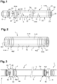
- FIG. 2 Such a structure is illustrated in figure 2 , in which we find a conduit element 1 which comprises an inner tube 2 (for air conduction) and an outer tube 3, separated by systems of annular spacers 4a at the ends.
- a conduit element 1 which comprises an inner tube 2 (for air conduction) and an outer tube 3, separated by systems of annular spacers 4a at the ends.
- an intermediate tube 7 is interposed between the inner tube 2 and the outer tube 3 to create two superimposed annular spaces 5, one interior 51 and the other exterior 52.
- the intermediate tube 7 may have a length identical or practically identical to those of the inner 2 and outer 3 tubes.
- this intermediate tube 7 can be made of a metallic, plastic, composite, cardboard, technical paper, fiber fabric, rigid foam, etc. material.
- Each annular spacer system 4a which is arranged at one end of the inner 2, outer 3 and intermediate 7 tubes is made up of two spacer structures 4a1, 4a2, each in the form of an independent tube section separating each pair of tubes, on the one hand the inner tube 2 and the intermediate tube 7, and on the other hand the intermediate tube 7 and the outer tube 3.
- the two spacer structures 4a1, 4a2 can be arranged in the same plane, or be offset from one another. They can be placed back from the end edges of the tubes or flush with them.
- the two spacer structures 4a1, 4a2 have general shapes and structures identical or similar to those of the annular spacer systems 4 described above in relation to the figure 1 .
- each spacer structure 4a1, 4a2 is in the form of a ring of material a few centimeters in length and with a thickness of between 5 and 25 mm, and preferably between 10 and 20 mm.
- outer 3 and intermediate 7 tubes may include structures of grooves or protuberances adapted to limit the possibilities of separation with these different tubes.
- spacer structures 4a1, 4a2 are advantageously made of a compressible material.
- they can be made of a material chosen from crosslinked polyolefin foams, in particular expanded polypropylene (PPE) or expanded polyethylene (PEE) foams, or any other insulation made from compressed fibers.
- PPE polypropylene
- PEE expanded polyethylene
- Such a structure makes it possible to obtain a thermally insulated conduit element 1, comprising two superimposed and closed annular spaces 5, trapping a still air blade.
- the sections of annular space 5 between the two tubes 2-7, on the one hand, and 7-3, on the other part can be filled with a thermal insulating material in bulk, in sheet form or in shell, with very wide freedom of choice in the nature of this insulating material (mineral, plant-based, synthetic, recycled material, etc.).
- the two spacer structures 4a1, 4a2 are introduced by force between the two tubes 2-7 and 7-3 and we can then obtain an assembly without any other means of joining, in particular without glue and without welding.
- Such an assembly is optimized by the use of a compressible material for producing the spacer structures 4a1, 4a2. It also makes it easier to assemble the conduit element, as well as its dismantling and recyclability at the end of its life.
- thermally insulated conduit elements 1, according to the figure 2 are joined together and assembled two by two by any appropriate assembly means to obtain the desired air transport network.
- these assembly means can use male-male type interlocking connectors, which cooperate with conduit elements 1 comprising two female type interlocking ends.
- the conduit elements 1 each comprise a first male-type nesting end and a second female-type nesting end; and two conduit elements 1 are directly assembled with each other by male-female type interlocking.
- the facing ends of two conduit elements 1 can be juxtaposed and assembled together by means of clamps.
- FIG. 3 illustrates a variant embodiment of a conduit element 1 according to the invention which comprises an inner tube 2 and an outer tube 3, concentric, spaced from one another to create an annular space 5 by means of systems of end-shaped annular spacers-end spacers 4a3.
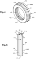
- the end spacer tips 4a3, one of which is shown in isolation on the figures 4 and 5 are in the general form of a ring of material, or a portion of tube, a few centimeters in length and with a thickness of between 5 and 25 mm, and preferably between 10 and 20 mm.
- Each ring of material 4a3 comprises: an outer ring 41, intended to come to bear against the inner surface 31 of the outer tube 3, an inner ring 42, intended to come to bear against the outer surface 22 of the inner tube 2, an outer face 43, oriented towards the outside, and an internal face 44, opposite, oriented towards the inside.
- At least some of the surfaces 41, 42 of the rings of material 4a3 in contact with the inner 2 and outer 3 tubes may comprise structures of grooves or protuberances adapted to limit the possibilities of separation between said spacer systems 4 and said inner tubes 2 and exterior 3.
- the end spacers 4a3 are made of a compressible, thermally insulating and waterproof material, or practically airtight, for example expanded polypropylene (PPE).
- PPE expanded polypropylene
- the two end spacer tips 4a3 are inserted by force between the two tubes 2 and 3 and an assembly is obtained without any other means of securing, in particular without glue or welding.
- the two end spacer tips 4a3 are not completely inserted between the two tubes 2 and 3, and their external face 43 extends externally relative to the end edges 24, 34 of the two inner tubes 2 and outer 3
- an external part 43a of the end spacer tips 4a3 extends projecting relative to the end edges 24, 34 of the two inner 2 and outer 3 tubes; and this projecting external part 43a is compressible due to the constituent material used.
- the part of the outer crown 41 of the end spacer tips 4a3 which comes into contact with the inner surface 31 of the outer tube 3 comprises a projecting circular groove 41b, arranged to cooperate with a complementary circular molding 35, provided in the surface facing the outer tube 3, to lock the assembly of the two elements.
- This locking is adapted to be carried out when the end edge 34 of the outer tube 3 abuts against the shoulder 41a of the end spacer tips 4a3. Such locking is facilitated due to the compressibility characteristics of the material constituting the end caps-spacers 4a3.
- the same type of locking can be provided between the end spacer tips 4a3 and the inner tube 2 and/or a possible intermediate tube.
- the assembly of a plurality of conduit elements 1 as shown in the Figure 3 can be made using clamps 8, as illustrated on the figures 3 And 5 .
- the clamps 8 are arranged to assemble two ends of two conduit elements 1 placed end to end, with the external faces 43 of their annular spacer systems 4a3 bearing against each other.
- clamps 8 comprise a circular strip 81, for example in the form of a metal strip, provided with a tightening loop 82, and the two side edges of which comprise locking edges 83 projecting inwards ( Figure 5 ).
- the ends of the two conduit elements 1 to be assembled each comprise a molding on the outer surface 32 of the outer tube 3.
- this molding is a recessed molding which corresponds to the locking molding 35 mentioned above.
- the distance which separates their two facing moldings 35 corresponds approximately to the width of the clamp 8, and therefore to the distance which separates its locking edges 83.
- the installation of the clamp 8 on the junction of the two conduit elements 1 allows the insertion of its locking edges 83 into the recessed moldings 35 of the two conduit elements 1 to be assembled, and these locking edges 83 of the clamp clamping 8 cooperate with said moldings 35 so as, when tightening said clamping collar 8 by means of its tightening loop 82, to compress said external faces 43 of spacers against each other.
- the shape of the moldings 35 is adapted to obtain such compression of the external parts 43a of the end spacer tips 4a3 when tightening the clamp 8.
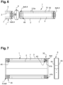
- FIG. 6 schematically illustrates a variant embodiment of the conduit element 1 of the Figure 3 , which further comprises an intermediate tube 7 interposed between the inner tube 2 and the outer tube 3 to create two superimposed annular spaces 5, one interior 51 and the other exterior 52.
- the 4a4 end spacer caps are similar to the 4a3 end spacer caps shown in the Figure 3 , but they also include an internal housing, not shown, provided in their internal face 44, for receiving one of the ends of the intermediate tube 7.
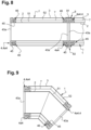
- FIG. 7 A possible embodiment of the conduit element 1 according to the principle of Figure 6 is illustrated on the Figure 7 , separated from a clamp 8. And the figure 8 illustrates two conduit elements 1 according to the Figure 7 , joined together and assembled by a clamp 8.
- the internal housing 45 provided in the internal face 44 of the end spacer tips 4a4, for receiving one of the ends of the intermediate tube 7.
- the inlet edge of the internal housing 45 comprises a chamfer 46 which is adapted to guide the end of the associated intermediate tube 7 and facilitate its insertion.
- the chamfer 46 is preferably arranged on the outer edge of the internal housing 45.
- conduit element 1 of the figures 7 And 8 here in the shape of an elbow, comprising an intermediate tube 7 interposed between the inner tube 2 and the outer tube 3 to create two superimposed annular spaces 5, one interior 51 and the other exterior 52.
- the three concentric tubes 2, 3 and 7 are assembled by two end spacers 4a4.
- FIG. 10 illustrates yet another alternative embodiment of the conduit element of the figures 7 to 9 , in the general shape of a T, with a main section of conduit element, here horizontal, associated with a secondary section of conduit element, here inclined at 45°.
- intermediate tubes 7 can be interposed between the inner tube 2 and the outer tube 3.
- the Figure 11 illustrates an embodiment in which the conduit element 1 comprises two intermediate tubes 7 (marked 7a and 7b) arranged concentrically between the inner tube 2 and the outer tube 3.
- the four tubes 2, 3, 7a and 7b are assembled by two end spacer tips 4a5.
- These two end spacer tips 4a5 are similar to the end spacer tips 4a3 and 4a4 described above, but here they include two internal housings 45 for receiving the ends of the two intermediate tubes 7a and 7b.
- the corresponding conduit element 1 then comprises three superimposed annular spaces 5, one interior 51, another exterior 52 and an intermediate 53.
- the external faces 43 of the end spacer tips 4a3, 4a4, 4a5 can include complementary interlocking structures adapted to allow a temporary assembly between two joined conduit elements 1, while waiting for the installation of a clamp.
- the structural characteristics of the duct element 1 according to the invention allow the air transport network obtained to be both efficient in insulation and sealing, with low pressure losses. They also allow rapid assembly and offer a guarantee of installation results.
Landscapes
- Engineering & Computer Science (AREA)
- General Engineering & Computer Science (AREA)
- Mechanical Engineering (AREA)
- Chemical & Material Sciences (AREA)
- Combustion & Propulsion (AREA)
- Manufacturing & Machinery (AREA)
- Thermal Insulation (AREA)
- Duct Arrangements (AREA)
Applications Claiming Priority (1)
| Application Number | Priority Date | Filing Date | Title |
|---|---|---|---|
| FR2207805A FR3138491A1 (fr) | 2022-07-28 | 2022-07-28 | Elément de conduit isolé thermiquement et réseau de transport d’air obtenu par l’assemblage d’une pluralité de tels éléments de conduit |
Publications (3)
| Publication Number | Publication Date |
|---|---|
| EP4311968A1 true EP4311968A1 (de) | 2024-01-31 |
| EP4311968C0 EP4311968C0 (de) | 2024-11-20 |
| EP4311968B1 EP4311968B1 (de) | 2024-11-20 |
Family
ID=83899891
Family Applications (1)
| Application Number | Title | Priority Date | Filing Date |
|---|---|---|---|
| EP23187935.4A Active EP4311968B1 (de) | 2022-07-28 | 2023-07-26 | Thermisch isoliertes leitungselement und durch die montage einer vielzahl solcher leitungselemente erhaltenes lufttransportnetz |
Country Status (4)
| Country | Link |
|---|---|
| EP (1) | EP4311968B1 (de) |
| ES (1) | ES3000663T3 (de) |
| FR (1) | FR3138491A1 (de) |
| PL (1) | PL4311968T3 (de) |
Citations (5)
| Publication number | Priority date | Publication date | Assignee | Title |
|---|---|---|---|---|
| US4502370A (en) * | 1983-04-15 | 1985-03-05 | Interpace Corporation | Insulated chimney assembly |
| US6113155A (en) * | 1996-04-12 | 2000-09-05 | Constructions Metalliques Mecaniques Beirens C.M.M. Beirens, Sa | Modular nesting metal conduit, in particular for discharging fumes |
| US6543575B1 (en) * | 2000-06-14 | 2003-04-08 | Lindab Ab | Double-walled structure and connection arrangement |
| EP3282164A1 (de) * | 2016-08-12 | 2018-02-14 | PROMAT GmbH | Rohrleitungssystem |
| BE1026788A1 (nl) * | 2018-11-15 | 2020-06-11 | Pronox Nv | Ventilatiesysteem |
-
2022
- 2022-07-28 FR FR2207805A patent/FR3138491A1/fr active Pending
-
2023
- 2023-07-26 EP EP23187935.4A patent/EP4311968B1/de active Active
- 2023-07-26 ES ES23187935T patent/ES3000663T3/es active Active
- 2023-07-26 PL PL23187935.4T patent/PL4311968T3/pl unknown
Patent Citations (5)
| Publication number | Priority date | Publication date | Assignee | Title |
|---|---|---|---|---|
| US4502370A (en) * | 1983-04-15 | 1985-03-05 | Interpace Corporation | Insulated chimney assembly |
| US6113155A (en) * | 1996-04-12 | 2000-09-05 | Constructions Metalliques Mecaniques Beirens C.M.M. Beirens, Sa | Modular nesting metal conduit, in particular for discharging fumes |
| US6543575B1 (en) * | 2000-06-14 | 2003-04-08 | Lindab Ab | Double-walled structure and connection arrangement |
| EP3282164A1 (de) * | 2016-08-12 | 2018-02-14 | PROMAT GmbH | Rohrleitungssystem |
| BE1026788A1 (nl) * | 2018-11-15 | 2020-06-11 | Pronox Nv | Ventilatiesysteem |
Also Published As
| Publication number | Publication date |
|---|---|
| ES3000663T3 (en) | 2025-03-03 |
| FR3138491A1 (fr) | 2024-02-02 |
| EP4311968C0 (de) | 2024-11-20 |
| EP4311968B1 (de) | 2024-11-20 |
| PL4311968T3 (pl) | 2025-03-10 |
Similar Documents
| Publication | Publication Date | Title |
|---|---|---|
| EP3175181A1 (de) | Verbesserte enthalpietauscher | |
| CA3004997C (fr) | Raccord tubulaire rapide avec bague secable pour connexion fluidique securisee | |
| EP2791441B1 (de) | Wärmedämmsystem und entsprechendes montageverfahren | |
| EP2791440B1 (de) | Wärmedämmungssystem mit zwischenlagern zum halten von vip-platten und entsprechendes montageverfahren | |
| EP4311968B1 (de) | Thermisch isoliertes leitungselement und durch die montage einer vielzahl solcher leitungselemente erhaltenes lufttransportnetz | |
| EP3167322B1 (de) | Endkupplung für eine faseroptische schaltung, verfahren zum anschluss solch einer schaltung an eine derartige kupplung und entsprechendes dichtelement | |
| EP1533585B1 (de) | Wärmetauscher mit Plattenstapel | |
| FR2965334A1 (fr) | Dispositif de type boitier de soufflerie | |
| EP3234488B1 (de) | Wärmeaustauschplatte mit mikrokanälen und wärmetauscher mit mindestens einer solchen platte | |
| EP3099994B1 (de) | Wärmetauscher für ein kraftfahrzeug | |
| FR3002376A1 (fr) | Bouchon d'etancheite pour cable electrique contre les infiltrations d'air dans les batiments et procede de pose du cable electrique | |
| FR2494395A1 (fr) | Raccords notamment pour tuyaux en matiere plastique, particulierement les raccords en te, et procede de construction s'y rapportant | |
| EP3001133B1 (de) | Wärmetauscher für kraftfahrzeug | |
| FR3011563A1 (fr) | Plancher thermiquement isolant incluant des panneaux piv, module de plancher et kit d'assemblage | |
| EP4438934A1 (de) | Verbindungsschelle zum positionieren und halten der enden zweier endseitig miteinander verbundener leitungselemente | |
| FR3008439A1 (fr) | Lame de bardage | |
| EP1083378B1 (de) | Doppelwandiger Rohrabschnitt und Verfahren zur Herstellung von rohrförmigen Elementen | |
| WO2025040672A1 (fr) | Dispositif de contrôle thermique redondant de grande longueur à structures diphasiques complexes, procédé d'assemblage et procédé de fabrication | |
| EP2485221A1 (de) | Druckfeste dielektrische Struktur | |
| FR3138178A3 (fr) | Conduit modulaire rigide, isolé thermiquement, adapté au transport d’un fluide gazeux | |
| WO2005121678A1 (fr) | Embout de tube pour element de circuit hydraulique, en particulier pour echanger de chaleur | |
| FR3052606A1 (fr) | Embout d'entree de conducteurs electriques dans une boite electrique | |
| FR3032215A1 (fr) | Boite de reservation et son procede de montage | |
| FR2819575A1 (fr) | Chassis support et procede de fabrication d'un tel chassis |
Legal Events
| Date | Code | Title | Description |
|---|---|---|---|
| PUAI | Public reference made under article 153(3) epc to a published international application that has entered the european phase |
Free format text: ORIGINAL CODE: 0009012 |
|
| STAA | Information on the status of an ep patent application or granted ep patent |
Free format text: STATUS: THE APPLICATION HAS BEEN PUBLISHED |
|
| AK | Designated contracting states |
Kind code of ref document: A1 Designated state(s): AL AT BE BG CH CY CZ DE DK EE ES FI FR GB GR HR HU IE IS IT LI LT LU LV MC ME MK MT NL NO PL PT RO RS SE SI SK SM TR |
|
| STAA | Information on the status of an ep patent application or granted ep patent |
Free format text: STATUS: REQUEST FOR EXAMINATION WAS MADE |
|
| RAP1 | Party data changed (applicant data changed or rights of an application transferred) |
Owner name: VITALOME |
|
| 17P | Request for examination filed |
Effective date: 20240418 |
|
| RBV | Designated contracting states (corrected) |
Designated state(s): AL AT BE BG CH CY CZ DE DK EE ES FI FR GB GR HR HU IE IS IT LI LT LU LV MC ME MK MT NL NO PL PT RO RS SE SI SK SM TR |
|
| GRAP | Despatch of communication of intention to grant a patent |
Free format text: ORIGINAL CODE: EPIDOSNIGR1 |
|
| STAA | Information on the status of an ep patent application or granted ep patent |
Free format text: STATUS: GRANT OF PATENT IS INTENDED |
|
| INTG | Intention to grant announced |
Effective date: 20240802 |
|
| GRAS | Grant fee paid |
Free format text: ORIGINAL CODE: EPIDOSNIGR3 |
|
| GRAA | (expected) grant |
Free format text: ORIGINAL CODE: 0009210 |
|
| STAA | Information on the status of an ep patent application or granted ep patent |
Free format text: STATUS: THE PATENT HAS BEEN GRANTED |
|
| AK | Designated contracting states |
Kind code of ref document: B1 Designated state(s): AL AT BE BG CH CY CZ DE DK EE ES FI FR GB GR HR HU IE IS IT LI LT LU LV MC ME MK MT NL NO PL PT RO RS SE SI SK SM TR |
|
| REG | Reference to a national code |
Ref country code: GB Ref legal event code: FG4D Free format text: NOT ENGLISH |
|
| REG | Reference to a national code |
Ref country code: CH Ref legal event code: EP |
|
| REG | Reference to a national code |
Ref country code: DE Ref legal event code: R096 Ref document number: 602023001092 Country of ref document: DE |
|
| REG | Reference to a national code |
Ref country code: IE Ref legal event code: FG4D Free format text: LANGUAGE OF EP DOCUMENT: FRENCH |
|
| U01 | Request for unitary effect filed |
Effective date: 20241212 |
|
| U07 | Unitary effect registered |
Designated state(s): AT BE BG DE DK EE FI FR IT LT LU LV MT NL PT RO SE SI Effective date: 20250102 |
|
| REG | Reference to a national code |
Ref country code: ES Ref legal event code: FG2A Ref document number: 3000663 Country of ref document: ES Kind code of ref document: T3 Effective date: 20250303 |
|
| PG25 | Lapsed in a contracting state [announced via postgrant information from national office to epo] |
Ref country code: IS Free format text: LAPSE BECAUSE OF FAILURE TO SUBMIT A TRANSLATION OF THE DESCRIPTION OR TO PAY THE FEE WITHIN THE PRESCRIBED TIME-LIMIT Effective date: 20250320 Ref country code: HR Free format text: LAPSE BECAUSE OF FAILURE TO SUBMIT A TRANSLATION OF THE DESCRIPTION OR TO PAY THE FEE WITHIN THE PRESCRIBED TIME-LIMIT Effective date: 20241120 |
|
| PG25 | Lapsed in a contracting state [announced via postgrant information from national office to epo] |
Ref country code: NO Free format text: LAPSE BECAUSE OF FAILURE TO SUBMIT A TRANSLATION OF THE DESCRIPTION OR TO PAY THE FEE WITHIN THE PRESCRIBED TIME-LIMIT Effective date: 20250220 |
|
| PG25 | Lapsed in a contracting state [announced via postgrant information from national office to epo] |
Ref country code: GR Free format text: LAPSE BECAUSE OF FAILURE TO SUBMIT A TRANSLATION OF THE DESCRIPTION OR TO PAY THE FEE WITHIN THE PRESCRIBED TIME-LIMIT Effective date: 20250221 |
|
| PG25 | Lapsed in a contracting state [announced via postgrant information from national office to epo] |
Ref country code: RS Free format text: LAPSE BECAUSE OF FAILURE TO SUBMIT A TRANSLATION OF THE DESCRIPTION OR TO PAY THE FEE WITHIN THE PRESCRIBED TIME-LIMIT Effective date: 20250220 |
|
| U20 | Renewal fee for the european patent with unitary effect paid |
Year of fee payment: 3 Effective date: 20250513 |
|
| PG25 | Lapsed in a contracting state [announced via postgrant information from national office to epo] |
Ref country code: SM Free format text: LAPSE BECAUSE OF FAILURE TO SUBMIT A TRANSLATION OF THE DESCRIPTION OR TO PAY THE FEE WITHIN THE PRESCRIBED TIME-LIMIT Effective date: 20241120 |
|
| PGFP | Annual fee paid to national office [announced via postgrant information from national office to epo] |
Ref country code: PL Payment date: 20250516 Year of fee payment: 3 |
|
| PG25 | Lapsed in a contracting state [announced via postgrant information from national office to epo] |
Ref country code: SK Free format text: LAPSE BECAUSE OF FAILURE TO SUBMIT A TRANSLATION OF THE DESCRIPTION OR TO PAY THE FEE WITHIN THE PRESCRIBED TIME-LIMIT Effective date: 20241120 |
|
| PG25 | Lapsed in a contracting state [announced via postgrant information from national office to epo] |
Ref country code: CZ Free format text: LAPSE BECAUSE OF FAILURE TO SUBMIT A TRANSLATION OF THE DESCRIPTION OR TO PAY THE FEE WITHIN THE PRESCRIBED TIME-LIMIT Effective date: 20241120 |
|
| PLBE | No opposition filed within time limit |
Free format text: ORIGINAL CODE: 0009261 |
|
| STAA | Information on the status of an ep patent application or granted ep patent |
Free format text: STATUS: NO OPPOSITION FILED WITHIN TIME LIMIT |
|
| PGFP | Annual fee paid to national office [announced via postgrant information from national office to epo] |
Ref country code: ES Payment date: 20250806 Year of fee payment: 3 |
|
| 26N | No opposition filed |
Effective date: 20250821 |