EP4313420B1 - Procédé et dispositif de vérification des points de pipettes - Google Patents
Procédé et dispositif de vérification des points de pipettes Download PDFInfo
- Publication number
- EP4313420B1 EP4313420B1 EP22716958.8A EP22716958A EP4313420B1 EP 4313420 B1 EP4313420 B1 EP 4313420B1 EP 22716958 A EP22716958 A EP 22716958A EP 4313420 B1 EP4313420 B1 EP 4313420B1
- Authority
- EP
- European Patent Office
- Prior art keywords
- pipette tips
- holding device
- held
- image data
- pipette
- Prior art date
- Legal status (The legal status is an assumption and is not a legal conclusion. Google has not performed a legal analysis and makes no representation as to the accuracy of the status listed.)
- Active
Links
Images







Classifications
-
- B—PERFORMING OPERATIONS; TRANSPORTING
- B01—PHYSICAL OR CHEMICAL PROCESSES OR APPARATUS IN GENERAL
- B01L—CHEMICAL OR PHYSICAL LABORATORY APPARATUS FOR GENERAL USE
- B01L9/00—Supporting devices; Holding devices
- B01L9/54—Supports specially adapted for pipettes and burettes
- B01L9/543—Supports specially adapted for pipettes and burettes for disposable pipette tips, e.g. racks or cassettes
-
- B—PERFORMING OPERATIONS; TRANSPORTING
- B01—PHYSICAL OR CHEMICAL PROCESSES OR APPARATUS IN GENERAL
- B01L—CHEMICAL OR PHYSICAL LABORATORY APPARATUS FOR GENERAL USE
- B01L9/00—Supporting devices; Holding devices
- B01L9/56—Means for indicating position of a recipient or sample in an array
-
- B—PERFORMING OPERATIONS; TRANSPORTING
- B29—WORKING OF PLASTICS; WORKING OF SUBSTANCES IN A PLASTIC STATE IN GENERAL
- B29C—SHAPING OR JOINING OF PLASTICS; SHAPING OF MATERIAL IN A PLASTIC STATE, NOT OTHERWISE PROVIDED FOR; AFTER-TREATMENT OF THE SHAPED PRODUCTS, e.g. REPAIRING
- B29C45/00—Injection moulding, i.e. forcing the required volume of moulding material through a nozzle into a closed mould; Apparatus therefor
- B29C45/17—Component parts, details or accessories; Auxiliary operations
- B29C45/76—Measuring, controlling or regulating
- B29C45/7686—Measuring, controlling or regulating the ejected articles, e.g. weight control
-
- G—PHYSICS
- G01—MEASURING; TESTING
- G01B—MEASURING LENGTH, THICKNESS OR SIMILAR LINEAR DIMENSIONS; MEASURING ANGLES; MEASURING AREAS; MEASURING IRREGULARITIES OF SURFACES OR CONTOURS
- G01B11/00—Measuring arrangements characterised by the use of optical techniques
- G01B11/24—Measuring arrangements characterised by the use of optical techniques for measuring contours or curvatures
- G01B11/2433—Measuring arrangements characterised by the use of optical techniques for measuring contours or curvatures for measuring outlines by shadow casting
-
- B—PERFORMING OPERATIONS; TRANSPORTING
- B01—PHYSICAL OR CHEMICAL PROCESSES OR APPARATUS IN GENERAL
- B01L—CHEMICAL OR PHYSICAL LABORATORY APPARATUS FOR GENERAL USE
- B01L2200/00—Solutions for specific problems relating to chemical or physical laboratory apparatus
- B01L2200/12—Specific details about manufacturing devices
-
- B—PERFORMING OPERATIONS; TRANSPORTING
- B01—PHYSICAL OR CHEMICAL PROCESSES OR APPARATUS IN GENERAL
- B01L—CHEMICAL OR PHYSICAL LABORATORY APPARATUS FOR GENERAL USE
- B01L2200/00—Solutions for specific problems relating to chemical or physical laboratory apparatus
- B01L2200/14—Process control and prevention of errors
- B01L2200/143—Quality control, feedback systems
-
- B—PERFORMING OPERATIONS; TRANSPORTING
- B01—PHYSICAL OR CHEMICAL PROCESSES OR APPARATUS IN GENERAL
- B01L—CHEMICAL OR PHYSICAL LABORATORY APPARATUS FOR GENERAL USE
- B01L3/00—Containers or dishes for laboratory use, e.g. laboratory glassware; Droppers
- B01L3/02—Burettes; Pipettes
- B01L3/0275—Interchangeable or disposable dispensing tips
-
- B—PERFORMING OPERATIONS; TRANSPORTING
- B29—WORKING OF PLASTICS; WORKING OF SUBSTANCES IN A PLASTIC STATE IN GENERAL
- B29C—SHAPING OR JOINING OF PLASTICS; SHAPING OF MATERIAL IN A PLASTIC STATE, NOT OTHERWISE PROVIDED FOR; AFTER-TREATMENT OF THE SHAPED PRODUCTS, e.g. REPAIRING
- B29C2945/00—Indexing scheme relating to injection moulding, i.e. forcing the required volume of moulding material through a nozzle into a closed mould
- B29C2945/76—Measuring, controlling or regulating
- B29C2945/76003—Measured parameter
- B29C2945/761—Dimensions, e.g. thickness
- B29C2945/76103—Dimensions, e.g. thickness shrinkage, dilation, dimensional change, warpage
-
- B—PERFORMING OPERATIONS; TRANSPORTING
- B29—WORKING OF PLASTICS; WORKING OF SUBSTANCES IN A PLASTIC STATE IN GENERAL
- B29C—SHAPING OR JOINING OF PLASTICS; SHAPING OF MATERIAL IN A PLASTIC STATE, NOT OTHERWISE PROVIDED FOR; AFTER-TREATMENT OF THE SHAPED PRODUCTS, e.g. REPAIRING
- B29C2945/00—Indexing scheme relating to injection moulding, i.e. forcing the required volume of moulding material through a nozzle into a closed mould
- B29C2945/76—Measuring, controlling or regulating
- B29C2945/76344—Phase or stage of measurement
- B29C2945/76421—Removing or handling ejected articles
-
- B—PERFORMING OPERATIONS; TRANSPORTING
- B29—WORKING OF PLASTICS; WORKING OF SUBSTANCES IN A PLASTIC STATE IN GENERAL
- B29C—SHAPING OR JOINING OF PLASTICS; SHAPING OF MATERIAL IN A PLASTIC STATE, NOT OTHERWISE PROVIDED FOR; AFTER-TREATMENT OF THE SHAPED PRODUCTS, e.g. REPAIRING
- B29C2945/00—Indexing scheme relating to injection moulding, i.e. forcing the required volume of moulding material through a nozzle into a closed mould
- B29C2945/76—Measuring, controlling or regulating
- B29C2945/76451—Measurement means
- B29C2945/76461—Optical, e.g. laser
- B29C2945/76464—Optical, e.g. laser cameras
-
- B—PERFORMING OPERATIONS; TRANSPORTING
- B29—WORKING OF PLASTICS; WORKING OF SUBSTANCES IN A PLASTIC STATE IN GENERAL
- B29L—INDEXING SCHEME ASSOCIATED WITH SUBCLASS B29C, RELATING TO PARTICULAR ARTICLES
- B29L2031/00—Other particular articles
- B29L2031/753—Medical equipment; Accessories therefor
-
- G—PHYSICS
- G01—MEASURING; TESTING
- G01N—INVESTIGATING OR ANALYSING MATERIALS BY DETERMINING THEIR CHEMICAL OR PHYSICAL PROPERTIES
- G01N35/00—Automatic analysis not limited to methods or materials provided for in any single one of groups G01N1/00 - G01N33/00; Handling materials therefor
- G01N35/10—Devices for transferring samples or any liquids to, in, or from, the analysis apparatus, e.g. suction devices, injection devices
- G01N35/1065—Multiple transfer devices
Definitions
- the present invention relates to a method and a device for checking pipette tips and an injection molding system comprising at least one device for checking pipette tips as described below.
- Pipette tips are usually manufactured using the injection molding process, with the injection molding devices used usually having a number of cavities arranged in a circle, each of which is delimited by an injection molding tool.
- the problem is that the pressure conditions that occur during the injection molding process cause an inner part of the tool to be radially displaced from an original optimal position over time, so that the wall thickness of the pipette tips produced changes slightly over time.
- a method for assessing pipette tip distortion in which the distortion is recorded using image data.
- first and second image data of the pipette tip ends and pipette tip inlet openings are recorded with respect to a pipette tip group with a plurality of pipette tips, the viewing directions of the first and second image acquisition means being opposite to one another, and an average value of the deviation mass is then determined based on the deviation mass of the pipette tip outlet openings.
- this method is very complex in terms of equipment, since separate first and second image acquisition means are required.
- determining the target position of the pipette tip outlet openings using the second image acquisition means aligned with the inlet opening of the upper pipette tip end has proven to be difficult or error-prone in practice.
- the tolerances when determining the target position of the pipette tip using the second image acquisition means and the tolerances when determining the actual position using the first image acquisition means overlap, which leads to inaccuracies when determining the actual deviation. of the pipette tip distortion.
- the DE 10 2017 012 225 A1 a pressing device which, by exerting mechanical force on the pipette tip held in a holder, causes the pipette tip to be positioned particularly well in the holder.
- the pipette tip which is positioned in a defined position on the holder, can thus be subjected to measurement reliably and with a low error tolerance, with the image capture device provided for this purpose recording the position of the free end of the pipette tip.
- the distortion of the pipette tip is determined as the positional deviation of a predetermined area of the pipette tip held in the holder from a predefined target position of this area in the case of a distortion-free pipette tip.
- the disadvantage of this method is, on the one hand, that it is very complex in terms of equipment due to the large number of separate devices in the test device.
- a type of revolving mechanism for feeding a single pipette tip to the pressing device or the use of several image capture devices corresponding to the number of pipette tips held on the holder is proposed, which further increases the equipment complexity and the costs of such a testing device.
- the WO 2020/079170 A1 discloses a method and a device for checking pipette tips, wherein a reference area of a held pipette tip extending in the axial direction is detected by a first detection means and the symmetry axis of the pipette tip is calculated based on the reference area. To detect a curvature or slant of the injection molded part, the position of a symmetry axis section spaced apart from the reference area in the axial direction is detected by a second detection means and compared with the previously calculated symmetry axis.
- checking the pipette tips remains very time-consuming.
- the present invention is based on the object of eliminating these and other disadvantages of the prior art and in particular of specifying an advantageous method for checking the openings and the distortion of elongated injection molded parts such as pipette tips in particular, which can be carried out quickly, reliably and with little effort in relation to the test device required for this purpose. Furthermore, the present invention is based on the object of providing a test device suitable for carrying out the method.
- the object is achieved by a method for checking pipette tips, a device for checking pipette tips, which device is preferably designed to carry out the method according to the invention, and an injection molding system comprising a device according to the invention for checking pipette tips according to the independent patent claims.
- Further advantageous embodiments are the subject of the dependent patent claims. If no reference is made to a specific embodiment of the method according to the invention or to a specific embodiment of the device according to the invention, such advantageous embodiments basically relate to all of the embodiments of the method according to the invention or the device according to the invention described herein.
- the object is achieved by a method for checking pipette tips each extending along a longitudinal axis (L), wherein the method according to the invention comprises the following steps: a) providing pipette tips which are arranged in a first carrier; b) receiving pipette tips from the first carrier by a holding device comprising a plurality of receiving elements for receiving a pipette tip each; c) capturing first image data of the respective pipette tip outlet openings of the pipette tips received by the holding device by a first image capture device; d) capturing second image data of the pipette tips held in the holding device by a second image capture device.
- the optical axis of the second image capture device is aligned transversely to the respective longitudinal axis of the pipette tips held in the holding device and to the partial segments of the respective pipette tip surface areas of the held pipette tips facing the second image capture device.
- the second image data of several of the pipette tips held in the holding device are recorded simultaneously.
- the second image data of all of the pipette tips held in the holding device are recorded simultaneously; e) Determining whether the first and/or second image data are within predefined admissible limits or not.
- a data processing system Ejecting those pipette tips whose Step e) determined first and/or second image data lie outside the predefined admissible limits, into a waste container by the holding device; g) dispensing those pipette tips whose first and second image data determined in step e) lie within the predefined admissible limits, into a second carrier.
- the second carrier can in particular be a rack.
- this comprises the following steps: a) providing pipette tips which are arranged in a first carrier in a first matrix arrangement of rows and columns in the first carrier; b) receiving a row or column of pipette tips from the first matrix arrangement by a holding device comprising a plurality of receiving elements arranged in a row for receiving a pipette tip each.
- the longitudinal axes of the pipette tips held by the receiving elements lie essentially in a common plane; c) capturing first image data of the respective pipette tip outlet openings of the pipette tips held by the holding device by a first image capture device.
- the optical axis of the first image capture device is aligned with the respective longitudinal axis of the pipette tips held in the holding device, in particular parallel, and is aligned with the pipette tip outlet openings during the capture of the first image data; d) capturing second image data of the pipette tips held in the holding device by a second image capture device.
- the optical axis of the second image acquisition device is essentially perpendicular to the plane defined by the pipette tips held and to the partial segments of the respective pipette tip surfaces of the held pipette tips are aligned so that all pipette tips held in the holding device are arranged substantially in an image plane of the second image capture device.
- the second image data of all pipette tips held in the holding device are captured simultaneously; e) determining whether the first and/or second image data lie within predefined admissible limits or not with the aid of a data processing system; f) ejecting those pipette tips whose first and/or second image data determined in step e) lie outside the predefined admissible limits into a waste container through the holding device; g) dispensing those pipette tips whose first and second image data determined in step e) lie within the predefined admissible limits into a second carrier with a plurality of holes in a second matrix arrangement of rows and columns, the holes of which are suitable for holding the dispensed pipette tips.
- the pipette tips are dispensed by the holding device in such a way that the respective rows or columns of holes of the second carrier are filled one after the other without one or more empty holes remaining between two dispensed pipette tips.
- the method according to the invention allows the efficient assessment of all pipette tips to determine deviations of the pipette tips from a predefined standard using two image capture devices.
- the deviation of the pipette tips from a standard is a distortion of the injection molded part or a deviation of the pipette tips from a desired shape.
- a standard deviation of the pipette tips is defined as a position deviation of the pipette tip opening or a predetermined area of the pipette tip surface from the predefined target positions of these areas. measured. The theoretical center line is recorded with each image. A systematic error caused by test objects clamped at an angle, i.e. pipette tips, can be filtered out in this way.
- the distortion of a pipette tip to be tested is measured by comparing it with a previously measured, undistorted pipette tip.
- a standard deviation of the pipette tip also means the deviation of its surface finish from a predetermined target value.
- the surface finish is characterized in particular by the presence or absence of scratches, cloudy spots, perforations or other damage.
- matrix arrangement is understood to mean a preferably regular arrangement of holes designed to hold a pipette tip each, the holes being arranged in rows and columns. Each row comprises a number of n holes and each column comprises a number of m holes, so that the number of holes contained in the matrix arrangement results from the product of n and m.
- Such matrix arrangements are present, for example, in the containers for pipette tips known from the prior art, so-called racks.
- image capture device refers to a camera, in particular a camera with a lens and suitable lighting.
- Telecentric lenses are particularly suitable as lenses, as they eliminate negative edge effects of round objects, such as elongated Injection molded parts with a symmetrical axis, especially pipette tips, can be greatly reduced.
- the first carrier which provides pipette tips in a first matrix arrangement of rows and columns
- the second carrier is a rack having a plurality of holes which are arranged in a second matrix arrangement of rows and columns.
- the pipette tips to be tested are picked up from the first carrier by the holding device in step b) and the tested pipette tips are returned to the first carrier in step g), wherein pipette tips from a reservoir of tested pipette tips are used to replace the pipette tips that may have been discarded in step f) and to refill the first carrier.
- the pipette tips to be tested are removed from the first carrier and initially only the first image data of the pipette tips held by the holding device are recorded in step c) before the pipette tips checked in step c) are returned to the first carrier in a method step g').
- the pipette tips to be checked have not yet completely cooled down when the first image data is recorded by the first image recording device in step c).
- step g' the previously partially tested pipette tips are again picked up from the first carrier by the holding device in step b), whereupon the pipette tips undergo process steps c) to g) or d) to g) for complete testing.
- the holding device of the first matrix arrangement removes a complete row or a complete column of pipette tips in step b).
- the holding device removes all pipette tips from a row or a column of a rack in step b).
- the number of receiving elements of the holding device corresponds to the number of pipette tips provided in a row or column of the first matrix arrangement and/or the second matrix arrangement of holes in the second carrier.
- the holding device is matched to the first and/or second carriers used in the method according to the invention, whereby the method according to the invention can be carried out particularly cost-efficiently.
- the second image data can also be reliably and satisfactorily acquired if the longitudinal axes (L) of the pipette tips held by the receiving elements in the holding device do not lie essentially in a common plane.
- the pipette tips provided in step a) are arranged in the first carrier in at least one circular arrangement.
- the pipette tips provided in step a) are arranged in at least one circular arrangement of eight pipette tips evenly spaced from one another in the circumferential direction of the circular arrangement.
- the holding device receives a circular arrangement, in particular a complete circular arrangement, of pipette tips from the first carrier in step b).
- the holding device is rotated about its axis of rotation by an angle of rotation ⁇ in such a way that the contours of at least some of the pipette tips held in the holding device can be captured by the second image capture device.
- the rotation of the holding device about its axis of rotation causes that the contours of all pipette tips held in the holding device can be captured by the second image capture device.
- This second embodiment has the additional advantages that, by accommodating pipette tips in a circular arrangement, there is no need for automation upstream of the device according to the invention, which converts the circular arrangement, as is usually the case in the tool of an injection molding machine, into a linear arrangement.
- the pipette tips can thus be tested while maintaining the tool arrangement of the injection molding machine, without prior reorientation of the pipette tips. This significantly reduces the design and financial outlay as well as the space required for the device according to the invention.
- the "axis of rotation of the holding device” is understood to mean the axis of rotation extending in the direction of the pipette tips received by the holding device.
- detecttable contours in the context of the present invention means in particular the contours extending along the longitudinal direction of the pipette tip, so that the respective image capture device can distinguish pipette tips that are held in the holding device and are located in the optical axis of the respective image capture device from one another.
- pipette tips whose contours can be detected are not partially or even completely covered or superimposed by one or more other pipette tips in the optical axis of the respective image capture device to such an extent that they would be indistinguishable.
- the Contours can be completely captured, i.e. over essentially the entire length of the respective pipette tips.
- the holding device is rotated about its axis of rotation during the acquisition of the second image data in step d).
- the holding device preferably performs at least three-quarters of a rotation about its axis of rotation, i.e. a rotation of at least 270°.
- the rotation of the holding device about its axis of rotation makes it possible to record the second image data particularly easily and efficiently, since in this case additional drive means for rotating the individual recording elements can be dispensed with, which significantly reduces the complexity and maintenance requirements of the holding device.
- the optical axis of the second image capture device is also aligned with an illumination device attached to the holding device and arranged in the center of the circular arrangement of pipette tips during the acquisition of the second image data in step d).
- the illumination device is designed in such a way that it emits light in the direction of the second image capture device when the second image data is acquired in step d).
- the second image data of the pipette tips held in the holding device are additionally recorded in step d) by a third image capture device.
- the optical axis of the third image capture device is aligned during the acquisition of the second image data substantially perpendicular to the optical axis of the second image acquisition device and to the partial segments of the respective pipette tip surface areas of the held pipette tips facing the third image acquisition device.
- the holding device it may be necessary or advantageous to rotate the holding device about its axis of rotation by an angle of rotation ⁇ before capturing the second image data in step d) in such a way that the contours of a first part of the pipette tips held in the holding device can be captured, preferably completely, by the second image capture device, and that the contours of a second part of the pipette tips held in the holding device can be captured, preferably completely, by the third image capture device.
- a further image capture device i.e. the third image capture device
- a further image capture device for capturing the second image data makes it possible to reliably test even in the case of pipette tips that are located close to one another in the direction of rotation of the circular arrangement, where a single image capture device, i.e. the second image capture device, could no longer detect a gap between the pipette tips imaged adjacently in the beam path, in particular in the area of the respective recording elements, left and right with respect to the longitudinal axis of the respective pipette tips.
- an illumination device is attached to the holding device, which illuminates the circular Arrangement of pipette tips on the holding device is divided into two halves.
- the lighting device has two plane-parallel light-emitting surfaces for emitting light in the direction of the second image capture device and in the opposite direction to this direction.
- the optical axis of the second image capture device is aligned perpendicular to the lighting device attached to the holding device during the acquisition of the second image data in step d). Firstly, the second image data of one half of the pipette tips are acquired and the holding device is then rotated 180° about its axis of rotation before the second image data of the other half of the pipette tips are acquired.
- a further image capture device can be provided for acquiring second image data of the pipette tips held in the holding device.
- the optical axis of this further image capture device is aligned opposite to the optical axis of the second image capture device. The second image data of both halves of the circular arrangement of pipette tips are thus acquired simultaneously.
- the position of the pipette tips is detected with a measuring device and the first image acquisition device is thus triggered.
- the first image data are recorded in step c) when the pipette tips held in the holding device are moved transversely to the optical axis of the first image capture device and through the optical axis of the first image capture device relative to one another.
- the entry of the respective pipette tips, in particular the respective pipette tip outlet openings, into the optical axis of the first image capture device is determined by a measuring device and triggers the Acquisition of the first image data by the first image capture device.
- the measuring device for detecting the entry of the respective pipette tips into the optical axis of the first image capture device is, for example, a light barrier.
- the light barrier is, for example, directed transversely to the longitudinal axis of the pipette tips and at the pipette tip outlet opening, so that when the light barrier is interrupted, the acquisition of the first image data by the first image capture device is triggered.
- the measuring device for detecting the entry of the respective pipette tips into the optical axis of the first image capture device does not run through the optical axis of the first image capture device, but is arranged upstream of the first image capture device in the direction of movement of the holding device.
- the triggering of the acquisition of the first image data can be calculated or set by the distance between the measuring device and the optical axis of the first image capture device and the speed of movement of the holding device and the first image capture device relative to one another.
- step d) comprises the following method steps: i. Taking a first image of the pipette tips held in the holding device.
- the pipette tips are each in a first position; ii. Rotating the pipette tips held in the holding device about their longitudinal axis by a predetermined angle of rotation ⁇ into a second position; iii. Taking a second image of the pipette tips held in the holding device.
- the pipette tips are each in the second position;
- the angle of rotation ⁇ between the first position and the second position of the pipette tips is at least substantially 90°.
- the angle of rotation ⁇ between the first position and the second position of the pipette tips is between substantially 90° and substantially 180°.
- the angle of rotation ⁇ between the first position and the second position of the pipette tips is substantially 180°.
- the pipette tips are rotated into a number of intermediate positions corresponding to the number of additional images for taking further images.
- These intermediate positions lie between the first position and the second position.
- the one or more intermediate positions are reached, starting from the first position, by rotating the pipette tips by an angle of rotation ⁇ ', wherein the angle of rotation ⁇ ' is between 0° and 180°.
- the intermediate positions are preferably evenly distributed between the first position and the second position.
- the number of intermediate positions and the number of additional images is one to four, thereby achieving a particularly favorable ratio between measurement accuracy, amount of data recorded and to be processed and speed of the process.
- the pipette tips are each held in a force-fitting manner on the receiving elements of the holding device.
- the force-fitting connection can be made in a particularly efficient and reliable manner by applying negative pressure to the pipette tips.
- the pipette tips are positioned between the second image capturing device and a fixed relative to the second image capturing device when capturing the second image data in step d).
- arranged illumination device emits light onto the second image capture device in the direction opposite to the optical axis of the second image capture device.
- the data processing system controls a movement device for the controlled motor movement of the holding device in the direction of an X, Y and Z spatial axis.
- the movement device is only controlled for the controlled motor movement of the holding device in the direction of an X and Y spatial axis.
- the data processing system comprises a user interface and the method comprises the additional method step: h) selection of at least one receiving element of the holding device by a user, wherein the pipette tips held on the selected receiving elements are discarded as rejects as a result of the selection, regardless of the captured first and second image data in step f).
- Step h) is carried out before any of the steps a) to f).
- a user interface which allows a user to manually select at least one receiving element of the holding device or to deselect the pipette tips held on this or these receiving elements, has the advantage that the deselected pipette tips - regardless of the image data recorded in step c) and/or step d) - can be treated as rejects in step f) of the method according to the invention.
- This can be advantageous, for example, if it is already known from a method preceding the method according to the invention that certain positions of the first matrix arrangement contain faulty pipette tips.
- the manual selection by the user thus represents a second safety instrument which ensures that the pipette tips in question are not released into the second carrier.
- step d) also includes a surface inspection of the pipette tips to be tested in order to detect deviations of the pipette tip surfaces from a predefined standard.
- the second image capture device, the optionally available third image capture device and/or one or more further image capture devices, the respective optical axes of which are transverse to the longitudinal axis of the pipette tips held in the holding device and on the partial segments of the pipette tip surface are aligned.
- the object is further achieved by a device for checking pipette tips each extending along a longitudinal axis, which device is designed in particular to carry out the method described herein for checking pipette tips.
- the object is achieved by a device comprising a receiving position designed to provide a first carrier containing pipette tips and a holding device for receiving pipette tips from the first carrier provided at the receiving position.
- the holding device comprises a plurality of receiving elements, each of which is designed to receive a pipette tip.
- the device according to the invention further comprises a first image capture device for capturing first image data of the respective pipette tip outlet openings of the pipette tips received by the holding device and a second image capture device for capturing second image data of the pipette tips held in the holding device.
- There is also a data processing system which is connected in a signal-conducting manner to the first image capture device, the second image capture device and the holding device.
- Permissibility limits for the first and/or second image data are predefined, i.e. stored, in the data processing system.
- the device according to the invention further comprises a waste container designed to receive pipette tips ejected by the holding device and a dispensing position on which a second carrier can be provided.
- the device according to the invention has means for aligning the optical axis of the first image capture device parallel to the respective Longitudinal axis of the pipette tips held in the holding device and on the respective pipette tip outlet openings.
- These means are also designed to align the optical axis of the second image capture device transversely to the respective longitudinal axis of the pipette tips held in the holding device and on the partial segments of the respective pipette tip surface areas of the held pipette tips facing the second image capture device.
- the holding device of the device according to the invention can be moved back and forth between the receiving position, the first image capture device, the second image capture device, the waste container and/or the dispensing position.
- the device in a first embodiment, it comprises a receiving position designed to provide a first carrier containing pipette tips in a first matrix arrangement of rows and columns, and a holding device for receiving a row or column of pipette tips from the first matrix arrangement of rows and columns provided at the receiving position.
- the holding device comprises a plurality of receiving elements arranged in a row, each of which is designed to receive a pipette tip.
- the longitudinal axes of the pipette tips held by the receiving elements lie essentially in a common plane.
- the device according to the invention further comprises a first image capture device for capturing first image data of the respective pipette tip outlet openings of the pipette tips received by the holding device, and a second image capture device for capturing second image data of the pipette tips held in the holding device.
- the device according to the invention further comprises a data processing system which is connected in a signal-conducting manner to the first image capture device, the second image capture device and the holding device. Permissibility limits for the first and/or second image data are predefined, i.e. stored, in the data processing system.
- the device according to the invention further comprises a waste container designed to receive pipette tips ejected by the holding device and a dispensing position on which a second carrier with a plurality of holes in a second matrix arrangement of rows and columns can be provided.
- the holes in the second carrier are suitable for holding the pipette tips.
- the device according to the invention has means for aligning the optical axis of the first image capture device parallel to the respective longitudinal axis of the pipette tips held in the holding device and to the respective pipette tip outlet openings.
- These means are also designed to align the optical axis of the second image capture device essentially perpendicular to the plane defined by the held pipette tips and to the partial segments of the respective pipette tip jacket surfaces of the held pipette tips facing the second image capture device.
- the holding device of the device according to the invention can be moved back and forth between the receiving position, the first image capture device, the second image capture device, the waste container and/or the dispensing position and is designed to fill the respective rows or columns of holes of the second carrier with pipette tips one after the other, without one or more empty holes remaining between two dispensed pipette tips.
- the receiving position and/or the delivery position of the device according to the invention according to the first embodiment is each designed to provide at least one rack.
- the pipette tips are arranged in a circular arrangement in the first carrier.
- the arrangement of the receiving elements of the holding device corresponds to the circular arrangement of the pipette tips in the first carrier.
- the circular arrangement is in particular the tool arrangement of an injection molding machine upstream of the device according to the invention.
- the holding device has means for rotating the holding device about its axis of rotation.
- the holding device comprises an illumination device which is attached to the holding device and divides the circular arrangement of pipette tips into two halves.
- the illumination device has two plane-parallel light-emitting surfaces for emitting light in opposite directions.
- the holding device comprises an illumination device which is attached to the holding device and arranged in the center of the circular arrangement of pipette tips for emitting light in the direction of the second image capture device.
- the illumination device is designed in the form of a light bulb or cylindrical with a circumferential light-emitting surface, since such an illumination device emits the light evenly.
- the means for aligning the optical axes of the two image capture devices, ie the first image capture device and the second image capture device and, if applicable, the third image capture device or the further image capture device for capturing the second image data, and the pipette tips held in the holding device is a movement device that can be controlled by the data processing system for the controlled motor movement of the holding device in the direction of an X, Y and Z spatial axis.
- the holding device can preferably only be moved in the direction of an X and Y spatial axis by the movement device.
- the pipette tips can be rotated individually around the axis of rotation of the pipette tips, i.e. around their longitudinal axis, whereby only one camera is required to check the concentricity of the pipette tips, as will be explained in more detail below.
- the individual inspection of each pipette tip also solves the problem of faulty pipette tips ending up in the packaging container and already packaged, completely filled pipette tip holders having to be disposed of, or of faulty pipettes having to be replaced with fault-free pipettes at great expense.
- Pipette tip holders of this type are also known as "racks".
- faulty pipette tips can be sorted out beforehand, for example by the device throwing these faulty pipette tips into a container intended for rejects. This means that only pipette tips that meet the quality requirements predefined in each individual case are transferred to packaging containers by the device.
- the data processing system of the device according to the invention is equipped with one of the inventive Device upstream injection molding system, which produces pipette tips in several cavities in an injection molding tool, is connected in a signal-conducting manner.
- the pipette tips taken from the cavities of the injection molding tool can be traceably transferred to the first matrix arrangement of pipette tips described here.
- the data processing system of the device according to the invention can automatically find out which cavity is causing problems and then deselect the affected cavity or cavities.
- the pipette tips originating from a deselected cavity - regardless of the image data acquired in step c) or step d) of the method according to the invention - are treated as rejects and are in no case passed on to the second carrier in step g) of the method according to the invention.
- the device according to the invention further comprises a measuring device for determining the entry of the respective pipette tips, in particular the respective pipette tip outlet openings, into the optical axis of the first image capture device.
- the measuring device is connected to the first image capture device in a signal-conducting manner and is designed to trigger the capture of the first image data by the first image capture device.
- the measuring device for determining the entry of the respective pipette tips into the optical axis of the first image capture device is preferably a light barrier.
- Such a measuring device for triggering image capture has the advantage that it can accelerate the acquisition of the first image data.
- the holding device has means for rotating the pipette tips held in the holding device about their longitudinal axis.
- the means for rotating the pipette tips are designed to rotate the pipette tips from a first position to a second position by an angle of rotation ⁇ of at least substantially 90°.
- the angle of rotation ⁇ between the first position and the second position of the pipette tips is preferably between substantially 90° and substantially 180°.
- the angle of rotation ⁇ between the first position and the second position of the pipette tips is particularly preferably substantially 180°.
- the means for rotating the pipette tips held in the holding device comprise a gear on each receiving element.
- the gears of adjacent receiving elements mesh with one another and form a gear assembly, and can be rotated by a rotary drive.
- the rotary drive is preferably arranged at one end of the gear assembly. This allows the holding device to be designed to be particularly compact and space-saving.
- the means for rotating the pipette tips held in the holding device comprise a gear on each receiving element, wherein two adjacent gears are operatively connected to one another via an intermediate gear to form a gear assembly.
- at least one of the gears or one of the intermediate gears of the gear assembly is Rotatable by a rotary drive. This allows the entire gear assembly to rotate.
- the gears of adjacent receiving elements arranged on a receiving element may not mesh with each other.
- the gears can be rotated by a common rack and pinion drive or a common toothed belt. This means that all gears and thus all receiving elements can be rotated in the same direction by the rack and pinion drive or the toothed belt.
- the support means prevent the toothed belt from lifting off the gears and thus ensure uninterrupted and safe driving of the respective gears. It is particularly preferred to arrange the support means in the area of each contact point of the gears with the toothed belt.
- the means for rotating the pipette tips held in the holding device comprise an individual drive, for example an electric motor, on each receiving element.
- each receiving element can be rotated independently of the remaining receiving elements of the holding device by means of its individual drive.
- the means for rotating the pipette tips held in the holding device comprise a disk on each receiving element, which disk is arranged in a rotationally fixed manner in the circumferential direction of the respective receiving element.
- a rod drive is attached to the disks eccentrically in relation to the longitudinal axis of the respective receiving element. The rod drive converts a back and forth movement of a drive rod into a rotary movement of the receiving elements.
- the means for rotating the pipette tips held in the holding device are designed to rotate the pipette tips into intermediate positions between the first position and the second position.
- the means for rotating the pipette tips held in the holding device are designed to rotate the pipette tips into one to four intermediate positions between the first position and the second position.
- the intermediate positions are evenly distributed between the first position and the second position, which allows a particularly reliable checking of the concentricity of the respective pipette tips.
- the number of receiving elements of the holding device corresponds to the number of pipette tips provided in a row or column of the first matrix arrangement.
- the device according to the invention is designed to be particularly suitable for efficiently carrying out the method according to the invention, since the holding device in step b) of the method according to the invention can receive an entire row or column from the first matrix arrangement and feed it to the image capture devices.
- the holding device preferably comprises at least five, preferably at least ten and even better at least fifteen receiving elements, since the advantages of the method according to the invention, in particular with regard to its efficiency and speed, increase further with an increasing number of pipette tips tested simultaneously.
- the receiving elements each have a coupling attachment with a vacuum connection in order to hold the pipette tips on the receiving elements of the holding device by applying negative pressure.
- the coupling attachments are each designed in such a way that they can be inserted into the plug-on end of a pipette tip opposite the pipette tip outlet opening and, after the pipette tip is applied with negative pressure, a substantially positive fit and thus a certain tightness is established between the coupling connection and the pipette tip.
- Such a design of the receiving elements has the advantage that the pipette tips are reliably held and can also be easily ejected again by removing the negative pressure in the held pipette tips.
- a separate ejection device for ejecting the pipette tips from the receiving elements can preferably be dispensed with.
- the receiving elements are conically shaped, which facilitates the insertion of the receiving elements into the plug-on end of the pipette tips, increases the tightness between the receiving element and the pipette tip, and also ensures a certain frictional press fit between the coupling attachment and the coupling area of the pipette tip arranged near the plug-on end. This ensures that the pipette tips are held particularly securely on the respective holding elements.
- the device according to the invention comprises an illumination device which is arranged fixedly relative to the second image capture device.
- the illumination device is designed to emit light onto the second image capture device in the direction opposite to the optical axis of the second image capture device. This makes it possible to increase the contrast between the pipette tips and the background formed by the illumination device and to improve the capture of the second image data by the second image capture device, as described above.
- the data processing system of the device comprises a user interface which is designed for the selection of at least one receiving element of the holding device by a user.
- the pipette tips held on the selected receiving elements can be discarded as rejects regardless of the first and second image data recorded.
- this makes it possible to exclude pipette tips which were already identified as faulty prior to the method according to the invention from being released into the second carrier.
- the receiving elements of the holding device are designed to be movable relative to one another.
- their position relative to one another can be adapted to the first matrix arrangement and/or the second matrix arrangement of pipette tips, whereby the device according to the invention can be variably and is flexibly adaptable to different needs, ie different first and/or second matrix arrangements.
- the object is further achieved by an injection molding system for producing and packaging pipette tips, wherein the injection molding system according to the invention comprises at least one device according to the invention for checking pipette tips.
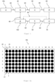
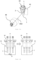
- FIG. 1 shows a schematic flow diagram of a variant of the method according to the invention for checking pipette tips according to the first embodiment.
- the method comprises the provision of pipette tips in a first matrix arrangement M1 of rows and columns in method step a).
- the pipette tips provided are picked up in step b) by a holding device 10 from the first matrix arrangement M1 of pipette tips, as will be described in more detail in the Figures 2a , 2b , 2d
- the pipette tips picked up in step b) are fed to a first image capture device 30 in step c) for capturing first image data of the pipette tips, as will be described in detail below.
- Figure 5 The pipette tips held on the holding device are then fed to a second image capture device 40 in step d) for capturing second image data of the pipette tips, as will be described in detail below.
- Figure 6 is executed.
- a data processing system 70 of the device with which the method according to the invention is carried out determines whether the first and/or second image data lie within predefined admissibility limits or not. These admissibility limits are stored in the data processing system 70.
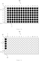
- Figure 2a shows a schematic plan view of a first carrier 20 with a plurality of holes 22 for holding pipette tips 1, which holes 22 are arranged in a first matrix arrangement M1 in the first carrier 20.
- each of the holes 22 in the first carrier 20 holds a pipette tip 1, so that the first carrier 20 provides a total of one hundred and five pipette tips 1.
- the first matrix arrangement M1 thus consists of fifteen columns AO and seven rows of holes 22.
- first carrier 20 around the perforated plate of a rack for pipette tips.
- the Figure 2a The situation presented represents only one possible starting situation of step a) of the Figure 1 1 represents a starting situation in which a first carrier 20 completely filled with pipette tips 1 is provided in step a) of the method according to the invention. However, it is also conceivable according to the invention that the first carrier 20 provided in step a) of the method according to the invention is not or no longer completely filled with pipette tips 1, as will be explained below.
- Figure 2c described, and/or the first matrix arrangement has one or more free spaces between two adjacent pipette tips 1, 1'.
- Figure 2b shows a schematic plan view of the Figure 2a shown first carrier 20, after step b) of the Figure 1 illustrated method, a complete column of pipette tips 1 was picked up from the first matrix arrangement M1 by a holding device (not shown), wherein the complete column in the illustrated embodiment comprises the positions A1 to A7 of the first carrier 20.
- Figure 2c shows a schematic plan view of a second carrier 20' with a plurality of holes 22 for holding pipette tips 1, which holes 22 are arranged in a second matrix arrangement M2 in the second carrier 20'.
- the second carrier 20' shown corresponds in terms of the number and arrangement of the holes 22 to the carrier from Figure 2a , i.e. that the first matrix arrangement M1 and the second matrix arrangement M2 are identical in this variant of the inventive method for checking pipette tips 1.
- the first matrix arrangement M1 and the second matrix arrangement M2 differ from one another, in particular with regard to the number of rows and columns and/or with regard to the distance of the holes 22 in the supports 20, 20' relative to one another, which holes 22 define the respective matrix arrangement.
- the holes 22 were made at positions A1 to A5 of the second carrier 20' in step g) of the Figure 1
- FIG. 2c The situation described arises, starting from the Figure 2b situation described, by step e) of the Figure 1
- the method shown in the figure showed that the first and/or second image data recorded in steps c) and d) of two of the seven pipette tips recorded in step b) were not within predefined acceptance limits (not shown). Subsequently, these two pipette tips 1 determined in step e) were used in step f) of the method described in Figure 1 ejected into a waste container (not shown) by the holding device.
- the five remaining pipette tips 1, whose first and second image data determined in step e) lie within the predefined admissibility limits, were dispensed into the second carrier 20' by the holding device in such a way that the holes 22 with the positions A1 to A5 of the column A of the second carrier 20' were filled one after the other, without one or more empty holes 22 remaining between two dispensed pipette tips 1.
- Figure 2d shows a schematic plan view of the Figure 2b shown first carrier 20, after in a further step b) of the in Figure 1
- another complete column of pipette tips 1 was taken up from the first matrix arrangement M1 by a holding device (not shown), the complete column being in the Figure 2d illustrated embodiment comprises the positions B1 to B7 of the first carrier 20.
- Figure 2e shows a schematic plan view of the second carrier 20' from Figure 2c , after in a further step g) of the Figure 1
- the seven pipette tips 1, which - as in Figure 2d shown - were taken up by a holding device from column B of the first carrier 20, were delivered into the second carrier 20' in such a way that the two empty holes 22, 22' with the positions A6 and A7 of column A of the second carrier 20' were first filled one after the other with one pipette tip 1 each and then the remaining five pipette tips 1 were delivered into the holes 22 with the positions B1 to B6 of column B of the second carrier 20', without one or more empty holes 22 remaining between two delivered pipette tips 1.
- the steps b) to g) of the Figure 1 The method shown can be repeated as often as desired, in particular until all holes 22 of the second carrier 20' have been filled with checked pipette tips 1, in which case any pipette tips remaining in the holding device are dispensed into a further carrier 20" with a plurality of holes 22 in a second matrix arrangement M2 of rows and columns, which holes 22 are suitable for holding the dispensed pipette tips 1.
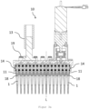
- FIG 3a shows a longitudinal section through a holding device 10 for use in a method or a device according to the first embodiment.
- the holding device 10 has fifteen receiving elements 11, each of which holds a pipette tip 1.
- the receiving elements 11 shown in this embodiment of the holding device 10 each have a conically shaped coupling attachment 18, which is connected in a fluid-conducting manner to a vacuum connection 19.
- the pipette tips 1 are held on the receiving elements 11 of the holding device 10 by applying negative pressure to the respective pipette tip cavity.
- the holding device 10 further comprises means 13 for rotating the pipette tips 1 held in the holding device 10 on the receiving elements 11 about their longitudinal axis L.
- the means 13 for rotating the held pipette tips 1 about their longitudinal axis L are each assigned to a receiving element 11 and, in the embodiment shown, comprise a gear 14 on each receiving element 11.
- the gears 14 mesh with one another and can be rotated by a common rotary drive.
- the means 13 shown enable the pipette tips 1 to be rotated from a first position to a second position by an angle of rotation of at least 90°.
- the holding device 10 is also attached to means 12 for aligning the pipette tips 1 held in the holding device 10, which is part of a movement device 60 - not visible in the illustration shown - for motor-driven movement of the holding device 10 in the direction of an X, Y and Z spatial axis.
- a movement device is, for example, an industrial robot, which is known per se to those skilled in the art.
- FIG 3b shows a front view of the holding device 10 from Figure 3a . From this view it is particularly evident that all receiving elements 11 are arranged in a row are.
- Each pipette tip 1 is held at its plug-in end 4 on a receiving element 11, which plug-in end 4 is located in the longitudinal direction L at the end opposite to its pipette tip outlet opening 2.
- the pipette tip surface 3 represents the area between the plug-in end 4 and the outlet opening 2 of a pipette tip 1.
- the longitudinal axes L of the pipette tips 1 held by the receiving elements 11 lie essentially in a common plane E.
- the pipette tips 1 arranged in a row are rotated by an angle of rotation with at least one drive 13.
- the individual pipette tips 1 are connected to one another by a mechanism, as described below in Figure 4 will be described in more detail using several conceivable examples.
- Figure 3c shows the Figure 3a shown holding device 10 in a detailed view and without pipette tips. From the Figure 3c In the view shown, it is particularly evident that the longitudinal axes L, L' of two adjacent receiving elements 11, 11' run parallel and that the receiving elements 11, 11' are each connected in a rotationally fixed manner to a crank 111, 111'.
- a gear 14, 14' is in turn arranged on the cranks 111, 111', which gears 14, 14' mesh with one another and are thus operatively connected to one another.
- the cranks 111, 111' are each supported by several bearings 112, 112' and sealed by means of a seal 113, 113'.
- the receiving elements 11, 11' each have a conically shaped coupling projection 18, 18', which is connected in a fluid-conducting manner to a vacuum connection 19, 19'.
- Figure 4 Further conceivable embodiments of the means 13 for rotating the pipette tips (not shown) held on the receiving elements of a holding device about their longitudinal axis L are shown schematically, in each case from a view in Direction of the longitudinal axis L of the pipette tips 1.
- Figure 4a shows five gears 14, 14', which do not mesh with each other and are movable by a common rack and pinion drive 17, ie are rotatable about their respective longitudinal axis L.
- a gear 14, 14' is arranged on each receiving element (not shown for reasons of clarity).
- Figure 4b shows an embodiment of the means 13 for rotating the pipette tips 1, in which a gear 14 is arranged on each of the five receiving elements. Between two adjacent gears 14, 14' an intermediate gear 141 is arranged, which is in operative connection with the two gears 14, 14'.
- the five gears 14 shown and the four intermediate gears 141 form a gear assembly 15.
- At least one of the gears 14, 14' and/or at least one of the intermediate gears 141 of the gear assembly 15 can be rotated by a rotary drive 16, for example by an electric drive, pneumatic cylinder or a lifting magnet.
- a rotary drive 16 for example by an electric drive, pneumatic cylinder or a lifting magnet.
- all gears 14, 14' - and thus also all pipette tips - can be rotated in the same direction, as indicated by the arrows in the gears 14, 14'.
- Figure 4c an embodiment is shown in which a gear 14 is arranged on each receiving element (not shown). Two adjacent gears 14, 14' mesh with each other to form a gear assembly 15.
- the gear assembly 15 is driven by a rotary drive 16 arranged at the right outer end of the gear assembly 15 in the illustration.
- each of the five receiving elements 11 is assigned an individual drive 80, for example an electric drive, pneumatic cylinder or a lifting magnet.
- the receiving elements 11 are not operatively connected to one another.
- each receiving element 11 can be rotated independently of the remaining receiving elements 11 of the holding device (not shown).
- each receiving element (not shown) comprises a disk 91 which is arranged in a rotationally fixed manner on the receiving elements in the circumferential direction U of the receiving elements.
- a rod drive 90 is eccentrically attached to the disks 91 in order to convert a back and forth movement of a drive rod 92 into a rotational movement of the disks 91 and thus of the receiving elements and the pipette tips.
- a gear 14 is arranged on each receiving element.
- the gears 14 do not mesh with one another and are rotatable by a common toothed belt 142.
- the six support means 143 shown prevent the toothed belt 142 from coming loose from the gears 14 and the drive of the receiving elements being interrupted.
- Figure 5 shows an arrangement comprising a holding device 10 and a first image capture device 30 in a perspective view.
- the pipette tip outlet openings 2 of the pipette tips 1 held in the holding device 10 are moved past the first image capture device 30 with the aid of the movement device 60 in such a way that the optical axis OA1 of the first image capture device 30 during the capture of the first image data is aligned parallel to the respective longitudinal axis L of the pipette tips 1 held on the receiving elements 11 and to the respective pipette tip outlet opening 2.
- the movement of the holding device 10 by the movement device 60 takes place in the direction of the plane E spanned by the held pipette tips 1 and substantially perpendicular to and through the optical axis OA1 of the first image capture device 30, wherein the pipette tips 1 each guided through the optical axis OA1 of the first image capture device 30 are each moved past the first image capture device 30 substantially in an image plane, i.e. each at the same distance from the first image capture device 30.
- a holding device is used on which the receiving elements 11 are arranged in a circle, the movement of the holding device 10 by the movement device 60 takes place accordingly such that the held pipette tips 1 are moved one after the other essentially perpendicular to and through the optical axis OA1 of the first image capture device 30, wherein the pipette tips 1 each guided through the optical axis OA1 of the first image capture device 30 are each moved past the first image capture device 30 at essentially the same distance.
- a measuring device 31 in the form of a light barrier can also be provided, which detects the entry of the respective pipette tip outlet openings 2 into the optical axis OA1 of the first image capture device 30.
- the measuring device 31 is connected to the first image capture device 30 in a signal-conducting manner (not shown) and triggers the acquisition of the first image data by the first image capture device 30 as soon as the light barrier is interrupted by a pipette tip 1.
- Figure 6 shows a perspective view of an arrangement comprising a holding device 10 and a second image capture device 40, as it is present during the capture of the second image data in step d) of the method according to the invention according to the first embodiment.
- the optical axis OA2 of the second image capture device 40 is aligned essentially perpendicular to the plane E defined by the held pipette tips 1, wherein this plane E lies essentially in an image plane of the second image capture device 40.
- the second image data of the respective sub-segments of the pipette tip surface 3, which face the second image capture device 40, can thus be captured simultaneously.
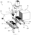
- FIG. 7 shows a variant of a device 100 for checking pipette tips 1 according to the first embodiment, in a perspective view.
- the device 100 comprises a receiving position 101, which is designed to provide a first rack 21 containing pipette tips in a first matrix arrangement M1, wherein the racks 21 in the embodiment shown are each arranged on a workpiece carrier 23.
- the workpiece carriers 23 can be moved to the receiving position 101 by a transport device, for example a conveyor belt 103.
- the device 100 also has a holding device 10 for receiving a complete row or complete column of pipette tips 1 from the first rack 20 provided at the receiving position 101.
- the holding device 10 comprises a plurality of receiving elements 11 arranged in a row, each of which is designed to receive a pipette tip 1.
- the holding device In a first matrix arrangement M1 of the first rack of, for example, eight rows and twelve columns, the holding device therefore has at least eight receiving elements 11 arranged in a row in order to be able to receive a complete column of eight pipette tips from one of the twelve columns of the first rack. According to the invention, however, it is conceivable for the holding device to have twelve receiving elements 11 arranged in a row, so that either a complete column of eight pipette tips can be received from one of the twelve columns of the first rack or a complete row of twelve pipette tips can be received from one of the eight rows of the first rack.
- the device 100 further comprises a first image capture device 30 for capturing first image data of the respective pipette tip outlet openings 2 and a second image capture device 40 for capturing second image data of the pipette tips 1 held in the holding device 10.
- a measuring device 31 is present for detecting the passage of the pipette tips through the optical axis of the first image capture device.
- the device 100 further comprises an illumination device 41 which is fixedly arranged relative to the second image capture device 40 and is designed to emit light onto the second image capture device 40 in the direction opposite to the optical axis of the second image capture device 40.
- a data processing system (not shown), in which admissibility limits for the first and/or second image data are predefined, is connected in a signal-conducting manner to at least the first image capture device 30, the second image capture device 40 and the holding device 10, so that pipette tips 1, the first or second image data of which are outside the admissibility limits predefined in the data processing system permissible limits, can be ejected from their respective receiving element 11 into a waste container (not shown).
- the device 100 further comprises a dispensing position 102, on which, in the embodiment shown, a second rack 21' is provided on a further workpiece carrier 23.
- the second rack 21' has a plurality of holes in a second matrix arrangement M2 of rows and columns, each hole being designed to hold a pipette tip 1.
- the device 100 further comprises means for aligning the pipette tips 1 held in the holding device 10 relative to the first image capture device 30 and the second image capture device 40, which in the embodiment shown are implemented by a movement device 60, an industrial robot.
- the movement device 60 is for moving the holding device 10 between the recording position 101, the first image capture device 30, the second image capture device 40, the Figure 7 waste container (not shown) and the delivery position 102.
- Figure 8 shows a carrier 20 for providing pipette tips 1 in a plurality of circular arrangements K in a schematic representation.
- the arrangement of the pipette tips 1 in the carrier 20 preferably corresponds to the arrangement of the pipette tips 1 in the cavities of the Figure 8 not shown injection molding tool from which they originate, so that the pipette tips produced can be easily transferred into the first carrier 20 after opening the injection molding tool while maintaining the arrangement present in the injection molding tool, the tool order.
- the first carrier 20 comprises eight circular arrangements K each with eight receptacles for one pipette tip each 1.
- injection molding tools with eight or a multiple of eight cavities e.g.
- Figure 9a shows a side view of a holding device 10 with eight circularly arranged receiving elements 11 for receiving a pipette tip 1 according to the second embodiment of the device according to the invention, as can be seen from the Figure 9c
- the bottom view shown in Figure 9c The arrangement of eight pipette tips 1 evenly spaced from each other in the circumferential direction of the circular arrangement K shown in FIG. 1 corresponds to the circular arrangement K as shown in FIG. Figure 8
- a longitudinal section through the holding device 10 along the line BB is shown in Figure 9b shown.
- the receiving elements 11 each have a conically shaped coupling attachment 18, which is connected in a fluid-conducting manner to an associated vacuum connection 19.
- the holding device 10 also has a rotation axis A extending in the direction of the pipette tips 1 received by the holding device 10.
- the rotation axis A of the holding device 10 thus runs essentially parallel to the longitudinal axes L of the pipette tips 1 held by the receiving elements 11 of the holding device 10.
- Figure 10a shows a further embodiment of a holding device 10 with a plurality of circularly arranged receiving elements 11 for receiving pipette tips 1 in a side view.
- the receiving elements 11 can each be equipped with a lifting function, whereby the pipette tips 1 can be placed down and/or picked up in a controlled manner along their longitudinal axes L. This can, for example, eliminate the risk of a collision between pipette tips received in the holding device 10 and already present in the second carrier.
- Figure 11a shows a perspective view of an arrangement comprising a holding device 10 and a second image capture device 40 according to the second embodiment of the device according to the invention.
- the optical axis OA2 of the second image capture device 40 is aligned transversely to the longitudinal axis L and to the partial segments of the respective pipette tip surface 3 of these eight pipette tips 1 facing it.
- the holding device 10 is positioned in the beam path between the illumination device 41 and the second image capture device 40.
- Figure 11b shows the holding device 10 from Figure 11a from the perspective of the second image capture device in Figure 11a in the direction of the illumination device 41.
- the contours of only five pipette tips 1 can be captured by the second image capture device, since three pipette tips are covered by three of the detectable pipette tips 1.
- the holding device 10 can be rotated about its rotation axis A by an angle of rotation ⁇ before the second image data is captured.
- Figure 12a shows a perspective view of an arrangement comprising a holding device 10, a second image capture device 40 and a third image capture device 43.
- the optical axes OA2 and OA3 of the second and third image capture devices 40, 43 are essentially perpendicular to each other and aligned with the partial segments of the respective pipette tip surface facing the respective image capture devices 40, 43.
- the pipette tips 1 held by the holding device 10 are positioned between the second image capture device 40 and an illumination device 41 as well as between the third image capture device 43 and a further illumination device 41'.
- FIG. 12b A schematic representation of the beam path through the pipette tips 1 held in the holding device 10 from Figure 12a is in Figure 12b As shown in Figure 12b
- the contours of the first part of the pipette tips held in the holding device 10 i.e. the contours of the contours of the The contours of the second part of the pipette tips held in the holding device 10, i.e. the contours of the pipette tips marked with reference numeral 1b
- the third image capture device since the pipette tips marked with reference numeral 1a are individually resolved in the beam path of the optical axis OA2 of the second image capture device.
- the contours of the second part of the pipette tips held in the holding device 10 i.e.
- the contours of the pipette tips marked with reference numeral 1b can be completely captured by the third image capture device, since the pipette tips marked with reference numeral 1b are individually resolved in the beam path of the optical axis OA3 of the third image capture device.
- Analogous to the Figures 11a and 11b In the embodiment described, even when a third image capture device is present, depending on the arrangement, size and distance of the pipette tips held, it may be advantageous to rotate the holding device 10 about its axis of rotation by an angle of rotation ⁇ before capturing the second image data in order to be able to capture the contours of the pipette tips 1a, 1b held in the holding device 10, preferably completely, by the second and third image capture devices 40, 43.
- Figure 13a shows a side view of an arrangement of a holding device 10 with an illumination device 44 attached thereto and a second image capture device 40.
- the illumination device 44 has two plane-parallel light-emitting surfaces 44a, 44b and divides the circular arrangement of pipette tips 1 into two halves, K1 and K2.
- the optical axis OA2 of the second image capture device 40 is aligned perpendicularly to the illumination device 44, specifically to the light-emitting surface 44a facing the second image capture device 40.
- the optical axis OA2 of the second image capture device is also aligned during the acquisition of the second image data to the the partial segments of the respective pipette tip surface 3 facing the second image acquisition device 40 are aligned.
- Figure 13b shows a perspective view of the arrangement of Figure 13a , wherein the light emitting surface 44b facing away from the second image capture device 40 and the half K2 of the circular arrangement of pipette tips 1 facing away from the second image capture device 40 are shown.
- the second image data of those pipette tips 1 which belong to the half K1 facing the second image capture device 40 are first captured.
- the holding device 10 is then rotated by 180° in order to face the other half K2 of pipette tips 1, which is separated from the first half K1 by the lighting device 44, towards the second image capture device 40.
- the two image capture devices for capturing second image data 40, 42 are aligned in opposite directions with the holding device 10 positioned between the two image capture devices 40, 42.
Landscapes
- Health & Medical Sciences (AREA)
- Clinical Laboratory Science (AREA)
- Chemical & Material Sciences (AREA)
- Chemical Kinetics & Catalysis (AREA)
- Physics & Mathematics (AREA)
- General Physics & Mathematics (AREA)
- Engineering & Computer Science (AREA)
- Manufacturing & Machinery (AREA)
- Mechanical Engineering (AREA)
- Automatic Analysis And Handling Materials Therefor (AREA)
Claims (25)
- Procédé de contrôle de pointes de pipettes (1) s'étendant chacune le long d'un axe longitudinal (L), le procédé comprenant les étapes de procédé suivantes :a) fournir des pointes de pipette (1) qui sont disposées dans un premier support (20) ;b) Réception de pointes de pipette (1) à partir du premier support (20) par un dispositif de maintien (10) comprenant une pluralité d'éléments de réception (11) destinés à recevoir chacun une pointe de pipette (1) ;c) l'acquisition, par un premier dispositif d'acquisition d'images (30), de premières données d'images des ouvertures respectives de sortie de pointe de pipette (2) des pointes de pipette (1) reçues par le dispositif de maintien (10) ;d) l'acquisition de deuxièmes données d'image des pointes de pipette (1) maintenues dans le dispositif de maintien (10) par un deuxième dispositif d'acquisition d'image (40) dont l'axe optique (OA2) est orienté, pendant l'acquisition des deuxièmes données d'image, transversalement à l'axe longitudinal (L) respectif des pointes de pipette (1) maintenues dans le dispositif de maintien (10) et sur les segments partiels, tournés vers le deuxième dispositif d'acquisition d'image (40), des surfaces d'enveloppe (3) respectives des pointes de pipette (1) maintenues ;e) déterminer si les premières et/ou deuxièmes données d'image se situent ou non dans des limites d'admissibilité prédéfinies, à l'aide d'un système de traitement de données (70) ;f) l'éjection, par le dispositif de maintien (10), dans un récipient à déchets (50), des pointes de pipette (1) dont les premières et/ou deuxièmes données d'image déterminées à l'étape e) se situent en dehors des limites d'admissibilité prédéfinies ;g) distribution des pointes de pipette (1) dont les premières et deuxièmes données d'image déterminées à l'étape e) se situent à l'intérieur des limites d'admissibilité prédéfinies, dans un deuxième support (20'), en particulier dans un rack (21, 21') ;les deuxièmes données d'image de plusieurs des pointes de pipette (1) maintenues dans le dispositif de maintien (10), de préférence de toutes les pointes de pipette (1) maintenues dans le dispositif de maintien (10), étant saisies simultanément dans l'étape d) du procédé.
- Procédé selon la revendication 1, dans lequel :- les pointes de pipette (1) mises à disposition à l'étape a) sont disposées dans le premier support (20) selon un premier agencement matriciel (M1) de rangées et de colonnes, en particulier dans un premier rack (21) ;- dans l'étape b), une rangée ou une colonne, de préférence une rangée complète ou une colonne complète, de pointes de pipettes (1) provenant du premier agencement de matrice (M1), en particulier du premier rack (21), est reçue par le dispositif de maintien (10), les éléments de réception (11) du dispositif de maintien (10) étant disposés en une rangée, et les axes longitudinaux (L) des pointes de pipettes (1) maintenues par les éléments de réception (11) se trouvant essentiellement dans un plan commun (E) ;- à l'étape c), l'axe optique (OA1) du premier dispositif de détection d'image est orienté, pendant la détection des premières données d'image, dans le même sens, en particulier parallèlement, par rapport à l'axe longitudinal respectif (L) des pointes de pipette (1) maintenues dans le dispositif de maintien (10) et vers l'ouverture de sortie respective (2) des pointes de pipette ;- à l'étape d), l'axe optique (OA2) du deuxième dispositif d'acquisition d'image (40) est orienté, pendant l'acquisition des deuxièmes données d'image, essentiellement perpendiculairement au plan (E) défini par les pointes de pipette (1) maintenues, de sorte que toutes les pointes de pipette (1) maintenues dans le dispositif de maintien (10) sont disposées essentiellement dans un plan d'image du deuxième dispositif d'acquisition d'image (40), les deuxièmes données d'image de toutes les pointes de pipette (1) maintenues dans le dispositif de maintien (10) étant acquises simultanément ;- le second support (20') à l'étape g) comprend une pluralité de trous (22) dans un second agencement matriciel (M2) de rangées et de colonnes, lesquels trous (22) sont adaptés pour maintenir les embouts de pipette distribués (1) ; etles pointes de pipette (1) étant distribuées dans l'étape g) du procédé par le dispositif de maintien (10) de telle sorte que les rangées ou colonnes respectives de trous (22) du deuxième support (20') sont remplies les unes après les autres, sans qu'il ne reste alors un ou plusieurs trous vides (22, 22') entre deux pointes de pipette (1) distribuées.
- Procédé selon la revendication 1, dans lequel :- les pointes de pipette (1) mises à disposition à l'étape a) sont disposées dans le premier support (20) en au moins un agencement circulaire (K), en particulier en au moins un agencement circulaire (K) de huit pointes de pipette (1) régulièrement espacées les unes des autres dans la direction circonférentielle de l'agencement circulaire (K) ;- à l'étape b), un ensemble circulaire (K), en particulier un ensemble circulaire complet (K), de pointes de pipettes (1) est prélevé sur le premier support (20) par le dispositif de maintien (10) ;- en option, à l'étape d), le dispositif de maintien (10) est tourné autour de son axe de rotation (A) s'étendant en direction des pointes de pipette (1) reçues par le dispositif de maintien (10) d'un angle de rotation (β) avant la saisie des deuxièmes données d'image, de telle sorte que les contours d'au moins une partie, de préférence de toutes les pointes de pipette (1) maintenues dans le dispositif de maintien (10), de préférence complètement, peuvent être saisis par le deuxième dispositif de saisie d'image (40).
- Procédé selon la revendication 3, dans lequel, à l'étape d), le dispositif de maintien (10) est tourné autour de son axe de rotation (A) s'étendant en direction des pointes de pipette (1) reçues par le dispositif de maintien (10) pendant l'acquisition des deuxièmes données d'image, en particulier le dispositif de maintien (10) effectue au moins trois quarts de tour autour de son axe de rotation (A) pendant l'acquisition des deuxièmes données d'image, et dans lequel, en option, à l'étape d), les pointes de pipette (1) reçues par le dispositif de maintien (10) sont tournées chacune autour de leur axe longitudinal (L).
- Procédé selon la revendication 3 ou 4, dans lequel les deuxièmes données d'image des pointes de pipette (1) maintenues dans le dispositif de maintien (10) sont en outre saisies à l'étape d) par un troisième dispositif de saisie d'image (43) dont l'axe optique (OA3) est orienté, pendant la saisie des deuxièmes données d'image, essentiellement perpendiculairement à l'axe optique (OA2) du deuxième dispositif de saisie d'image (40) et sur les segments partiels, tournés vers le troisième dispositif de saisie d'image (43), des surfaces d'enveloppe de pointe de pipette respectives (3) des pointes de pipette (1) maintenues, où, en option, à l'étape d), le dispositif de maintien (10) est tourné, avant la saisie des deuxièmes données d'image, autour de son axe de rotation (A) s'étendant en direction des pointes de pipette (1) reçues par le dispositif de maintien (10), d'un angle de rotation (β) tel que les contours d'une première partie (1a) des pointes de pipette (1) maintenues dans le dispositif de maintien (10), de préférence entièrement, peuvent être saisis par le deuxième dispositif de saisie d'image (40), et en ce que les contours d'une deuxième partie (1b) des pointes de pipette (1) maintenues dans le dispositif de maintien (10) peuvent être saisis, de préférence entièrement, par le troisième dispositif de saisie d'image (43).
- Procédé selon la revendication 3, dans lequel, pendant l'acquisition des deuxièmes données d'image à l'étape d), l'axe optique (OA2) des deuxièmes moyens d'acquisition d'image (40) est en outre perpendiculaire à un dispositif d'éclairage fixé aux moyens de support (10) et divisant l'ensemble circulaire (K) d'embouts de pipette (1) en deux moitiés (K1, K2), le dispositif d'éclairage (44) comprenant deux surfaces d'émission de lumière sensiblement planes et parallèles (44a, 44b) pour émettre de la lumière dans la direction du deuxième dispositif d'acquisition d'image (40) et dans la direction opposée à celle-ci, dans lequel, à l'étape d)i. les deuxièmes données d'image d'une moitié (K1) des pointes de pipette (1) sont saisies et le dispositif de maintien (10) est tourné de 180° autour de son axe de rotation (A) s'étendant en direction des pointes de pipette (1) reçues par le dispositif de maintien (10) avant la saisie des deuxièmes données d'image de l'autre moitié (K2) des pointes de pipette (1) ; ouii. un autre dispositif de saisie d'image (42) est prévu pour saisir des deuxièmes données d'image des pointes de pipette (1) maintenues dans le dispositif de maintien (10), dont l'axe optique est orienté en sens inverse de l'axe optique (OA2) du deuxième dispositif de saisie d'image (40), les deuxièmes données d'image des deux moitiés (K1, K2) de la disposition circulaire (K) de pointes de pipette (1) étant saisies simultanément.
- Procédé selon la revendication 4, dans lequel, pendant l'acquisition des secondes données d'image à l'étape d), l'axe optique (OA2) du second moyen d'acquisition d'image (40) est en outre aligné avec un moyen d'éclairage (45) fixé au moyen de support (10) et disposé au centre de l'agencement circulaire (K) d'embouts de pipette (1), lequel moyen d'éclairage (45) émet de la lumière en direction du second moyen d'acquisition d'image (40) lors de l'acquisition des secondes données d'image à l'étape d).
- Procédé selon l'une des revendications précédentes, dans lequel les premières données d'image sont saisies à l'étape c)lors du déplacement des pointes de pipette (1) maintenues dans le dispositif de maintien (10) transversalement à l'axe optique (OA1) du premier dispositif de saisie d'image (30) et par l'axe optique (OA1) du premier dispositif de saisie d'image (30) les unes par rapport aux autres, l'entrée des pointes de pipettes respectives (1), en particulier des ouvertures de sortie de pointes de pipettes respectives (2), dans l'axe optique (OA1) du premier dispositif de détection d'images (30) étant détectée par un dispositif de mesure (31), en particulier une barrière lumineuse (31), et déclenche la saisie des premières données d'image par le premier dispositif de saisie d'image (30), de préférence seul le dispositif de maintien (10) étant déplacé et le premier dispositif de saisie d'image (30) restant fixe, de préférence les ouvertures de sortie de pointe de pipette (2) respectives des pointes de pipette (1) maintenues dans le dispositif de maintien (10) étant amenées à passer devant le premier dispositif de saisie d'image essentiellement dans un seul plan d'image du premier dispositif de saisie d'image (30).
- Procédé selon l'une quelconque des revendications précédentes, dans lequel l'étape d) comprend les étapes de procédé suivantes :i. enregistrer une première image des pointes de pipette (1) maintenues dans le dispositif de maintien (10), les pointes de pipette (1) se trouvant chacune dans une première position (P1) ;ii. faire tourner les pointes de pipette (1) maintenues dans le dispositif de maintien (10) autour de leur axe longitudinal (L) d'un angle de rotation prédéterminé (α) dans une deuxième position (P2) ;iii. enregistrer une deuxième image des pointes de pipette (1) maintenues dans le dispositif de maintien (10), les pointes de pipette (1) se trouvant chacune dans la deuxième position (P2) ;dans lequel l'angle de rotation (α) entre la première position (P1) et la deuxième position (P2) est au moins sensiblement de 90°, de préférence entre sensiblement 90° et sensiblement 180°, de manière particulièrement préférée sensiblement de 180°.
- Procédé selon la revendication 9, dans lequel les pointes de pipette (1) sont tournées pour prendre d'autres images, de préférence d'une à quatre images supplémentaires, dans un nombre de positions intermédiaires (P3, P4, P5, P6) correspondant au nombre des autres images, lesquelles positions intermédiaires (P3, P4, P5, P6) sont situées entre la première position (P1) et la deuxième position (P2) et sont de préférence réparties uniformément entre la première position (P1) et la deuxième position (P2).
- Procédé selon l'une des revendications précédentes, dans lequel les pointes de pipette (1) sont respectivement maintenues par adhérence sur les éléments de réception (11) du dispositif de maintien (10), de préférence en soumettant les pointes de pipette (1) à une dépression.
- Procédé selon l'une quelconque des revendications précédentes, dans lequel l'installation de traitement de données (70) comprend une interface utilisateur (71) et le procédé comprend en outre une étape de procédé :h) sélection d'au moins un élément de réception (11) du dispositif de maintien (10) par un utilisateur, les pointes de pipette (1) maintenues sur les éléments de réception (11) sélectionnés étant rejetées en tant que rebut à la suite de la sélection, indépendamment des premières et deuxièmes données d'image saisies à l'étape f) ;dans lequel l'étape h) est effectuée avant l'une quelconque des étapes a) à f).
- Dispositif (100) pour contrôler des pointes de pipettes (1) s'étendant chacune le long d'un axe longitudinal (L), conçu en particulier pour la mise en oeuvre d'un procédé selon l'une des revendications précédentes, le dispositif (100) comprenant :- Une position de réception (101) configurée pour fournir un premier support (20) contenant des pointes de pipette (1) ;- Un dispositif de maintien (10) pour recevoir des pointes de pipette (1) à partir du premier support (20) mis à disposition à la position de réception (101), le dispositif de maintien (10) comprenant une pluralité d'éléments de réception (11), lesquels éléments de réception (11) sont conçus pour recevoir chacun une pointe de pipette (1) ;- un premier dispositif d'acquisition d'image (30) pour acquérir des premières données d'image des ouvertures de sortie d'embout de pipette respectives (2) des embouts de pipette (1) reçus par le dispositif de maintien (10) ;- un deuxième dispositif d'acquisition d'images (40) pour acquérir des deuxièmes données d'images des pointes de pipettes (1) maintenues dans le dispositif de maintien (10) ;- Un système de traitement de données (70) qui est relié par conduction de signaux au premier dispositif d'acquisition d'images (30), au deuxième dispositif d'acquisition d'images (40) et au dispositif de maintien (10), et dans lequel des limites d'admissibilité sont prédéfinies pour les premières et/ou les deuxièmes données d'image ;- un récipient à déchets (50) conçu pour recevoir les pointes de pipettes (1) éjectées par le dispositif de maintien (10) ;- une position de distribution (102), sur laquelle un deuxième support (20'), en particulier un rack (20, 20'), peut être mis à disposition ;dans lequel le dispositif (100) comprend des moyens (12) pour aligner l'axe optique (OA1) du premier dispositif d'imagerie (30) parallèlement à l'axe longitudinal respectif (L) des pointes de pipette (1) maintenues dans le dispositif de maintien (10) et sur les ouvertures de sortie de pointe de pipette respectives (2) et pour aligner l'axe optique (OA2) du deuxième dispositif de détection d'image (40) transversalement à l'axe longitudinal (L) respectif des pointes de pipette (1) maintenues dans le dispositif de maintien (10) et sur les segments partiels, tournés vers le deuxième dispositif de détection d'image (40), des surfaces d'enveloppe (3) respectives des pointes de pipette (1) maintenues, le dispositif de maintien (10) pouvant être déplacé en va-et-vient entre la position de réception (101), le premier dispositif de détection d'image (30), le deuxième dispositif de détection d'image (40), le récipient à déchets (50) et/ou la position de distribution (102).
- Dispositif (100) selon la revendication 13, dans lequel- les pointes de pipette (1) sont disposées dans le premier support (20) selon un premier agencement matriciel (M1) de rangées et de colonnes, en particulier le premier support (20) est un premier rack (21) ;- le dispositif de maintien (10) est conçu pour recevoir une rangée ou une colonne de pointes de pipettes (1) provenant du premier agencement matriciel (M1) de rangées et de colonnes, en particulier du premier rack (21), et les éléments de réception (11) du dispositif de maintien (10) sont disposés en une rangée, les axes longitudinaux (L) des pointes de pipettes (1) maintenues par les éléments de réception (11) se trouvant essentiellement dans un plan commun (E) ;- le deuxième support (20'), en particulier le rack (21, 21'), comprend une pluralité de trous (22) dans un deuxième agencement matriciel (M2) de rangées et de colonnes, lesquels trous (22) sont adaptés pour maintenir les pointes de pipette (1) ;- les moyens (12) pour orienter l'axe optique (OA2) du deuxième dispositif d'acquisition d'image (40) sont conçus pour orienter l'axe optique (OA2) du deuxième dispositif d'acquisition d'image (40) sensiblement perpendiculairement au plan (E) défini par les pointes de pipette (1) maintenues ; et- le dispositif de maintien (10) étant conçu pour remplir successivement les rangées ou colonnes respectives de trous (22) du deuxième support (20') avec des pointes de pipette (1), sans qu'il ne reste alors un ou plusieurs trous vides (22, 22') entre deux pointes de pipette (1, 1') distribuées.
- Dispositif (100) selon la revendication 13, dans lequel les pointes de pipette (1) sont disposées dans le premier support (20) selon une disposition circulaire (K), et dans lequel la disposition des éléments de réception (11) du dispositif de retenue (10) correspond à la disposition circulaire (K) des pointes de pipette (1) dans le premier support (20).
- Dispositif (100) selon la revendication 15, dans lequel le dispositif de maintien (10) comporte des moyens (121) pour faire tourner le dispositif de maintien (10) autour de son axe de rotation (A) s'étendant en direction des pointes de pipettes (1) reçues par le dispositif de maintien (10).
- Dispositif (100) selon la revendication 15 ou 16, dans lequel le dispositif de maintien (10)- comprend un dispositif d'éclairage (44) fixé au dispositif de maintien (10) et divisant l'agencement circulaire (K) de pointes de pipettes (1) en deux moitiés (K1, K2), le dispositif d'éclairage (44) présentant deux surfaces d'émission de lumière (44a, 44b) à faces planes et parallèles pour émettre de la lumière dans des directions opposées ; ou- un dispositif d'éclairage (45) fixé au dispositif de maintien (10) et disposé au centre de l'agencement circulaire (K) de pointes de pipettes (1) pour émettre de la lumière en direction du deuxième dispositif de saisie d'image (40), le dispositif d'éclairage (45) étant en particulier de forme cylindrique avec une surface d'émission de lumière (45a) périphérique.
- Dispositif (100) selon l'une des revendications 13 à 17, le dispositif (100) comprenant en outre un dispositif de mesure (31), en particulier une barrière photoélectrique (31), pour détecter l'entrée des pointes de pipette respectives (1), en particulier des ouvertures de sortie de pointe de pipette respectives (2), dans l'axe optique (OA1) du premier dispositif d'acquisition d'image (30), lequel dispositif de mesure (31) est relié par conduction de signaux au premier dispositif d'acquisition d'image (30) et est conçu pour déclencher la saisie des premières données d'image par le premier dispositif d'acquisition d'image (30).
- Dispositif (100) selon l'une des revendications 13 à 18, dans lequel le dispositif de maintien (10) comporte des moyens (13) pour faire tourner les pointes de pipette (1) maintenues dans le dispositif de maintien (10) autour de leur axe longitudinal (L), lesquels moyens (13) sont configurés pour faire tourner les pointes de pipette (1) d'une première position (P1) à une deuxième position (P2) d'un angle de rotation (α) d'au moins sensiblement 90°, de préférence entre sensiblement 90° et sensiblement 180°, de manière particulièrement préférée de sensiblement 180°.
- Dispositif (100) selon la revendication 19, dans lequel les moyens (13) pour faire tourner les pointes de pipette (1) maintenues dans le dispositif de maintien (10) comprennent :- une roue dentée (14) sur chaque élément de réception (11), lesquelles roues dentées (14) s'engrènent pour former un ensemble de roues dentées (15) et peuvent être mises en rotation par un entraînement rotatif (16) disposé de préférence à une extrémité de l'ensemble de roues dentées (15) ; ou- une roue dentée (14) sur chaque élément de réception (11), deux roues dentées (14, 14') voisines étant respectivement en liaison active l'une avec l'autre par l'intermédiaire d'une roue dentée intermédiaire (141) en formant un ensemble de roues dentées (15), au moins l'une des roues dentées (14) et/ou au moins l'une des roues dentées intermédiaires (141) de l'ensemble de roues dentées (15) pouvant être tournée par un entraînement rotatif (16) ; ou- une roue dentée (14) sur chaque élément de réception (11), lesquelles roues dentées (14) ne s'engrènent pas et peuvent être tournées par un entraînement à crémaillère commun (17) ; ou- une roue dentée (14) sur chaque élément de réception (11), lesquelles roues dentées (14) ne s'engrènent pas et peuvent être mises en rotation par une courroie dentée commune (142), des moyens de support (143) étant de préférence prévus pour assurer la liaison fonctionnelle entre les roues dentées (14) et la courroie dentée (142) ; ou- un entraînement individuel (80), en particulier un moteur électrique (80), sur chaque élément de réception (11), chaque élément de réception (11) pouvant être tourné par l'entraînement individuel (80) indépendamment des éléments de réception restants (11) du dispositif de retenue (10) ; ou- un disque (91) sur chaque élément de réception (11), lesquels disques (91) sont disposés respectivement dans la direction périphérique (U) des éléments de réception (11) de manière à ne pas pouvoir tourner sur les éléments de réception (11) et sur lesquels disques (91) s'applique respectivement de manière excentrée un entraînement à tige (90) pour transformer un mouvement de va-et-vient d'une tige d'entraînement (92) en un mouvement de rotation des éléments de réception (11).
- Dispositif (100) selon l'une des revendications 13 à 20, dans lequel les moyens (13) pour faire tourner les pointes de pipette (1) maintenues dans le dispositif de maintien (10) sont conçus pour faire tourner les pointes de pipette (1) dans des positions intermédiaires (P3, P4, P5, P6), lesquelles positions intermédiaires (P3, P4, P5, P6) sont situées entre la première position (P1) et la deuxième position (P2) et sont de préférence réparties uniformément entre la première position (P1) et la deuxième position (P2).
- Dispositif (100) selon la revendication 14 ou l'une des revendications 18 à 21, dans lequel le nombre d'éléments de réception (11) du dispositif de maintien (10) correspond au nombre d'embouts de pipette (1) mis à disposition dans une rangée ou une colonne du premier agencement matriciel (M1), le dispositif de maintien (10) comprenant de préférence au moins 5, de préférence au moins 10 et encore mieux au moins 15 éléments de réception (11).
- Dispositif (100) selon l'une des revendications 13 à 22, dans lequel les éléments de réception (11) comprennent chacun un appendice de couplage (18), en particulier de forme conique, qui est ou peut être relié par conduction de fluide à un raccord de vide (19), afin de maintenir les pointes de pipette (1) sur les éléments de réception (11) du dispositif de maintien (10) en les soumettant à une dépression.
- Dispositif (100) selon la revendication 14 ou l'une des revendications 18 à 23, dans lequel les éléments de réception (11) du dispositif de maintien (10) sont conçus mobiles les uns par rapport aux autres, de sorte que leur position les uns par rapport aux autres peut être adaptée au premier agencement matriciel (M1) et/ou au deuxième agencement matriciel (M2) de pointes de pipettes.
- Installation de moulage par injection (200) comprenant au moins un dispositif (100) de contrôle de pointes de pipettes (1) selon l'une des revendications 13 à 24.
Applications Claiming Priority (2)
| Application Number | Priority Date | Filing Date | Title |
|---|---|---|---|
| EP21164105.5A EP4063015A1 (fr) | 2021-03-22 | 2021-03-22 | Procédé et dispositif de vérification des points de pipettes |
| PCT/EP2022/057534 WO2022200375A1 (fr) | 2021-03-22 | 2022-03-22 | Procédé et dispositif de contrôle de pointes de pipettes |
Publications (3)
| Publication Number | Publication Date |
|---|---|
| EP4313420A1 EP4313420A1 (fr) | 2024-02-07 |
| EP4313420B1 true EP4313420B1 (fr) | 2025-02-19 |
| EP4313420C0 EP4313420C0 (fr) | 2025-02-19 |
Family
ID=75173031
Family Applications (2)
| Application Number | Title | Priority Date | Filing Date |
|---|---|---|---|
| EP21164105.5A Withdrawn EP4063015A1 (fr) | 2021-03-22 | 2021-03-22 | Procédé et dispositif de vérification des points de pipettes |
| EP22716958.8A Active EP4313420B1 (fr) | 2021-03-22 | 2022-03-22 | Procédé et dispositif de vérification des points de pipettes |
Family Applications Before (1)
| Application Number | Title | Priority Date | Filing Date |
|---|---|---|---|
| EP21164105.5A Withdrawn EP4063015A1 (fr) | 2021-03-22 | 2021-03-22 | Procédé et dispositif de vérification des points de pipettes |
Country Status (5)
| Country | Link |
|---|---|
| US (1) | US20240173906A1 (fr) |
| EP (2) | EP4063015A1 (fr) |
| CN (1) | CN117320813A (fr) |
| MX (1) | MX2023011096A (fr) |
| WO (1) | WO2022200375A1 (fr) |
Families Citing this family (3)
| Publication number | Priority date | Publication date | Assignee | Title |
|---|---|---|---|---|
| CN117664046B (zh) * | 2023-12-01 | 2024-12-03 | 苏州巨帧图远科技有限公司 | 一种Tip头圆跳动的检测算法 |
| CN119608516A (zh) * | 2025-02-12 | 2025-03-14 | 北京大学 | 旋涂装置、旋涂方法及电子设备 |
| CN120890612B (zh) * | 2025-10-09 | 2025-12-16 | 江苏科曼生物科技有限公司 | 一种新型环保材料的移液器吸头密封性检测装置 |
Citations (2)
| Publication number | Priority date | Publication date | Assignee | Title |
|---|---|---|---|---|
| DE102017012225A1 (de) * | 2017-11-09 | 2019-05-09 | Ma Micro Automation Gmbh | Prüfverfahren und Prüfvorrichtung |
| DE102018120963A1 (de) * | 2018-08-28 | 2020-03-05 | Hekuma Gmbh | Verfahren und Vorrichtung zum Verpacken von Spritzgussteilen |
Family Cites Families (7)
| Publication number | Priority date | Publication date | Assignee | Title |
|---|---|---|---|---|
| DE19909298B4 (de) | 1999-03-03 | 2005-01-13 | Siemens Ag | Verfahren zur Kontrolle von Haltevorrichtungen für Bauelemente in Bestückautomaten |
| WO2001096226A1 (fr) * | 2000-06-13 | 2001-12-20 | Cedes Ag | Dispositif de securite pour portes d'ascenseur |
| DE102014102280B3 (de) | 2014-02-21 | 2015-08-06 | Waldorf Technik Gmbh & Co. Kg | Verfahren und Vorrichtung zur Beurteilung eines Pipettenspitzenverzugs und/oder eines Spritzgusswerkzeugfehlers |
| CN106395529B (zh) * | 2015-07-27 | 2020-01-31 | 奥的斯电梯公司 | 监测系统、具有监测系统的电梯门系统和方法 |
| AT519601A1 (de) * | 2017-02-14 | 2018-08-15 | Liberda Viktor | Verfahren und vorrichtung zum steuern einer tür, vorzugsweise schiebetür |
| DE102018126019A1 (de) | 2018-10-19 | 2020-04-23 | Hekuma Gmbh | Verfahren und Vorrichtung zum Überprüfen von Spritzgussteilen, insbesondere Pipettenspitzen |
| EP3967472A1 (fr) * | 2020-09-11 | 2022-03-16 | Gritec AG | Procédé et dispositif d'emballage des pièces moulées par injection |
-
2021
- 2021-03-22 EP EP21164105.5A patent/EP4063015A1/fr not_active Withdrawn
-
2022
- 2022-03-22 CN CN202280035600.4A patent/CN117320813A/zh active Pending
- 2022-03-22 US US18/551,633 patent/US20240173906A1/en active Pending
- 2022-03-22 WO PCT/EP2022/057534 patent/WO2022200375A1/fr not_active Ceased
- 2022-03-22 MX MX2023011096A patent/MX2023011096A/es unknown
- 2022-03-22 EP EP22716958.8A patent/EP4313420B1/fr active Active
Patent Citations (2)
| Publication number | Priority date | Publication date | Assignee | Title |
|---|---|---|---|---|
| DE102017012225A1 (de) * | 2017-11-09 | 2019-05-09 | Ma Micro Automation Gmbh | Prüfverfahren und Prüfvorrichtung |
| DE102018120963A1 (de) * | 2018-08-28 | 2020-03-05 | Hekuma Gmbh | Verfahren und Vorrichtung zum Verpacken von Spritzgussteilen |
Also Published As
| Publication number | Publication date |
|---|---|
| EP4063015A1 (fr) | 2022-09-28 |
| CN117320813A (zh) | 2023-12-29 |
| EP4313420A1 (fr) | 2024-02-07 |
| WO2022200375A1 (fr) | 2022-09-29 |
| US20240173906A1 (en) | 2024-05-30 |
| EP4313420C0 (fr) | 2025-02-19 |
| MX2023011096A (es) | 2023-10-02 |
Similar Documents
| Publication | Publication Date | Title |
|---|---|---|
| EP4313420B1 (fr) | Procédé et dispositif de vérification des points de pipettes | |
| DE2427054C3 (de) | Vorrichtung zum Prüfen von maschinengeformten Artikeln | |
| DE3920888C2 (de) | Verfahren zur Prüfung der Enden von gestapelten Zigaretten | |
| EP3504538A1 (fr) | Système d'inspection optique pour préformes | |
| EP1036003A1 (fr) | Procede pour verifier que des groupes de cigarettes sont complets et que celles-ci sont suffisamment remplies | |
| EP2499501B1 (fr) | Dispositif d'extraction de contenants et machine d'emballage | |
| EP2913107B1 (fr) | Procédé et dispositif d'évaluation d'une déformation de pointes de pipettes et/ou une erreur d'outil de moulage par injection | |
| WO1994000249A1 (fr) | Procede et dispositif pour trier des capsules | |
| EP3578158A1 (fr) | Machine de remplissage de capsules avec unité de nettoyage et détecteur de corps étranger | |
| WO2013026504A1 (fr) | Procédé et dispositif de vérification des produits tabagiques en forme de tige | |
| EP4033227A1 (fr) | Procédé de détection optique de défauts des articles en céramique | |
| DE4202172C1 (en) | Testing surface and shape of similar small objects e.g. medicinal tabless - directing cameras onto rotatable discs with recesses for objects quality control | |
| DE19511854A1 (de) | Vorrichtung und Verfahren zum Prüfen von kleinen Gegenständen | |
| DE69302070T2 (de) | Anlage zur Behandlung, zum Ordnen und zum Sortieren von kurzen zylindrischen Körpern, wie zum Beispiel Kernbrennstofftabletten | |
| EP4115871A1 (fr) | Dispositif de transfert pour une capsule et machine à remplir des capsules pourvue de dispositif de transfert | |
| EP3854730B1 (fr) | Dispositif et procédé d'identification, de mesure et de positionnement de marchandises de détail | |
| DE2364843A1 (de) | Verfahren und vorrichtung zum automatischen und kontinuierlichen untersuchen von behaeltern | |
| EP1806043B1 (fr) | Procede de verification optique de composants electroniques | |
| DE102022129394A1 (de) | UV-Inspektion zur Identifizierung mangelhafter Beschichtung am Getränkedosenboden | |
| EP0316652B1 (fr) | Procédé et dispositif pour contrôler des cigarettes | |
| DE102022128726A1 (de) | Isolatorsystem und Verfahren | |
| DE202021102829U1 (de) | Halbautomatische Beladeeinrichtung zur statistischen Kontrolle, Inspektion, Vermessung, Prüfung und automatischen Auswahl von Kleinteilen aller Art aus Metall, Kunststoff und anderen Materialien | |
| DE4324109A1 (de) | Gewindeprüfvorrichtung | |
| DE202021104040U1 (de) | Wiegevorrichtung für eine Kapsel und Kapselfüllmaschine mit Wiegevorrichtung | |
| EP4338842B1 (fr) | Procédé d'emballage pour pointes de pipettes ou récipients de réaction médical avec contrôle latéral, dispositif d'emballage et système de moulage par injection |
Legal Events
| Date | Code | Title | Description |
|---|---|---|---|
| STAA | Information on the status of an ep patent application or granted ep patent |
Free format text: STATUS: UNKNOWN |
|
| STAA | Information on the status of an ep patent application or granted ep patent |
Free format text: STATUS: THE INTERNATIONAL PUBLICATION HAS BEEN MADE |
|
| PUAI | Public reference made under article 153(3) epc to a published international application that has entered the european phase |
Free format text: ORIGINAL CODE: 0009012 |
|
| STAA | Information on the status of an ep patent application or granted ep patent |
Free format text: STATUS: REQUEST FOR EXAMINATION WAS MADE |
|
| 17P | Request for examination filed |
Effective date: 20230906 |
|
| AK | Designated contracting states |
Kind code of ref document: A1 Designated state(s): AL AT BE BG CH CY CZ DE DK EE ES FI FR GB GR HR HU IE IS IT LI LT LU LV MC MK MT NL NO PL PT RO RS SE SI SK SM TR |
|
| DAV | Request for validation of the european patent (deleted) | ||
| DAX | Request for extension of the european patent (deleted) | ||
| REG | Reference to a national code |
Ref country code: DE Ref legal event code: R079 Free format text: PREVIOUS MAIN CLASS: B01L0009000000 Ipc: B29L0031000000 Ref country code: DE Ref legal event code: R079 Ref document number: 502022002946 Country of ref document: DE Free format text: PREVIOUS MAIN CLASS: B01L0009000000 Ipc: B29L0031000000 |
|
| RIC1 | Information provided on ipc code assigned before grant |
Ipc: G01N 35/10 20060101ALI20240719BHEP Ipc: G01B 11/24 20060101ALI20240719BHEP Ipc: B29C 45/76 20060101ALI20240719BHEP Ipc: B01L 3/02 20060101ALI20240719BHEP Ipc: B01L 9/00 20060101ALI20240719BHEP Ipc: B29L 31/00 20060101AFI20240719BHEP |
|
| GRAP | Despatch of communication of intention to grant a patent |
Free format text: ORIGINAL CODE: EPIDOSNIGR1 |
|
| STAA | Information on the status of an ep patent application or granted ep patent |
Free format text: STATUS: GRANT OF PATENT IS INTENDED |
|
| INTG | Intention to grant announced |
Effective date: 20240830 |
|
| GRAS | Grant fee paid |
Free format text: ORIGINAL CODE: EPIDOSNIGR3 |
|
| GRAA | (expected) grant |
Free format text: ORIGINAL CODE: 0009210 |
|
| STAA | Information on the status of an ep patent application or granted ep patent |
Free format text: STATUS: THE PATENT HAS BEEN GRANTED |
|
| RAP1 | Party data changed (applicant data changed or rights of an application transferred) |
Owner name: ROCHE DIAGNOSTICS INTERNATIONAL AG |
|
| AK | Designated contracting states |
Kind code of ref document: B1 Designated state(s): AL AT BE BG CH CY CZ DE DK EE ES FI FR GB GR HR HU IE IS IT LI LT LU LV MC MK MT NL NO PL PT RO RS SE SI SK SM TR |
|
| REG | Reference to a national code |
Ref country code: GB Ref legal event code: FG4D Free format text: NOT ENGLISH |
|
| REG | Reference to a national code |
Ref country code: CH Ref legal event code: EP |
|
| REG | Reference to a national code |
Ref country code: IE Ref legal event code: FG4D Free format text: LANGUAGE OF EP DOCUMENT: GERMAN |
|
| REG | Reference to a national code |
Ref country code: DE Ref legal event code: R096 Ref document number: 502022002946 Country of ref document: DE |
|
| U01 | Request for unitary effect filed |
Effective date: 20250303 |
|
| U07 | Unitary effect registered |
Designated state(s): AT BE BG DE DK EE FI FR IT LT LU LV MT NL PT RO SE SI Effective date: 20250311 |
|
| U20 | Renewal fee for the european patent with unitary effect paid |
Year of fee payment: 4 Effective date: 20250319 |
|
| PG25 | Lapsed in a contracting state [announced via postgrant information from national office to epo] |
Ref country code: RS Free format text: LAPSE BECAUSE OF FAILURE TO SUBMIT A TRANSLATION OF THE DESCRIPTION OR TO PAY THE FEE WITHIN THE PRESCRIBED TIME-LIMIT Effective date: 20250519 |
|
| PG25 | Lapsed in a contracting state [announced via postgrant information from national office to epo] |
Ref country code: PL Free format text: LAPSE BECAUSE OF FAILURE TO SUBMIT A TRANSLATION OF THE DESCRIPTION OR TO PAY THE FEE WITHIN THE PRESCRIBED TIME-LIMIT Effective date: 20250219 |
|
| PG25 | Lapsed in a contracting state [announced via postgrant information from national office to epo] |
Ref country code: ES Free format text: LAPSE BECAUSE OF FAILURE TO SUBMIT A TRANSLATION OF THE DESCRIPTION OR TO PAY THE FEE WITHIN THE PRESCRIBED TIME-LIMIT Effective date: 20250219 |
|
| PG25 | Lapsed in a contracting state [announced via postgrant information from national office to epo] |
Ref country code: IS Free format text: LAPSE BECAUSE OF FAILURE TO SUBMIT A TRANSLATION OF THE DESCRIPTION OR TO PAY THE FEE WITHIN THE PRESCRIBED TIME-LIMIT Effective date: 20250619 Ref country code: NO Free format text: LAPSE BECAUSE OF FAILURE TO SUBMIT A TRANSLATION OF THE DESCRIPTION OR TO PAY THE FEE WITHIN THE PRESCRIBED TIME-LIMIT Effective date: 20250519 |
|
| PG25 | Lapsed in a contracting state [announced via postgrant information from national office to epo] |
Ref country code: HR Free format text: LAPSE BECAUSE OF FAILURE TO SUBMIT A TRANSLATION OF THE DESCRIPTION OR TO PAY THE FEE WITHIN THE PRESCRIBED TIME-LIMIT Effective date: 20250219 |
|
| PG25 | Lapsed in a contracting state [announced via postgrant information from national office to epo] |
Ref country code: GR Free format text: LAPSE BECAUSE OF FAILURE TO SUBMIT A TRANSLATION OF THE DESCRIPTION OR TO PAY THE FEE WITHIN THE PRESCRIBED TIME-LIMIT Effective date: 20250520 |
|
| PG25 | Lapsed in a contracting state [announced via postgrant information from national office to epo] |
Ref country code: SM Free format text: LAPSE BECAUSE OF FAILURE TO SUBMIT A TRANSLATION OF THE DESCRIPTION OR TO PAY THE FEE WITHIN THE PRESCRIBED TIME-LIMIT Effective date: 20250219 |
|
| PG25 | Lapsed in a contracting state [announced via postgrant information from national office to epo] |
Ref country code: CZ Free format text: LAPSE BECAUSE OF FAILURE TO SUBMIT A TRANSLATION OF THE DESCRIPTION OR TO PAY THE FEE WITHIN THE PRESCRIBED TIME-LIMIT Effective date: 20250219 |
|
| REG | Reference to a national code |
Ref country code: CH Ref legal event code: H13 Free format text: ST27 STATUS EVENT CODE: U-0-0-H10-H13 (AS PROVIDED BY THE NATIONAL OFFICE) Effective date: 20251023 |
|
| PG25 | Lapsed in a contracting state [announced via postgrant information from national office to epo] |
Ref country code: SK Free format text: LAPSE BECAUSE OF FAILURE TO SUBMIT A TRANSLATION OF THE DESCRIPTION OR TO PAY THE FEE WITHIN THE PRESCRIBED TIME-LIMIT Effective date: 20250219 |
|
| PG25 | Lapsed in a contracting state [announced via postgrant information from national office to epo] |
Ref country code: MC Free format text: LAPSE BECAUSE OF FAILURE TO SUBMIT A TRANSLATION OF THE DESCRIPTION OR TO PAY THE FEE WITHIN THE PRESCRIBED TIME-LIMIT Effective date: 20250219 |
|
| PLBE | No opposition filed within time limit |
Free format text: ORIGINAL CODE: 0009261 |
|
| STAA | Information on the status of an ep patent application or granted ep patent |
Free format text: STATUS: NO OPPOSITION FILED WITHIN TIME LIMIT |
|
| PG25 | Lapsed in a contracting state [announced via postgrant information from national office to epo] |
Ref country code: CH Free format text: LAPSE BECAUSE OF NON-PAYMENT OF DUE FEES Effective date: 20250331 |
|
| PG25 | Lapsed in a contracting state [announced via postgrant information from national office to epo] |
Ref country code: IE Free format text: LAPSE BECAUSE OF NON-PAYMENT OF DUE FEES Effective date: 20250322 |
|
| 26N | No opposition filed |
Effective date: 20251120 |
|
| U20 | Renewal fee for the european patent with unitary effect paid |
Year of fee payment: 5 Effective date: 20260219 |