EP4313471B1 - Dispositif et procédé de soudage sous vide, avec une constriction afin de créer un effet venturi - Google Patents
Dispositif et procédé de soudage sous vide, avec une constriction afin de créer un effet venturi Download PDFInfo
- Publication number
- EP4313471B1 EP4313471B1 EP22717756.5A EP22717756A EP4313471B1 EP 4313471 B1 EP4313471 B1 EP 4313471B1 EP 22717756 A EP22717756 A EP 22717756A EP 4313471 B1 EP4313471 B1 EP 4313471B1
- Authority
- EP
- European Patent Office
- Prior art keywords
- edge
- welding
- vacuum
- circumferential
- bore
- Prior art date
- Legal status (The legal status is an assumption and is not a legal conclusion. Google has not performed a legal analysis and makes no representation as to the accuracy of the status listed.)
- Active
Links
Images


Classifications
-
- B—PERFORMING OPERATIONS; TRANSPORTING
- B23—MACHINE TOOLS; METAL-WORKING NOT OTHERWISE PROVIDED FOR
- B23K—SOLDERING OR UNSOLDERING; WELDING; CLADDING OR PLATING BY SOLDERING OR WELDING; CUTTING BY APPLYING HEAT LOCALLY, e.g. FLAME CUTTING; WORKING BY LASER BEAM
- B23K26/00—Working by laser beam, e.g. welding, cutting or boring
- B23K26/20—Bonding
- B23K26/21—Bonding by welding
-
- B—PERFORMING OPERATIONS; TRANSPORTING
- B23—MACHINE TOOLS; METAL-WORKING NOT OTHERWISE PROVIDED FOR
- B23K—SOLDERING OR UNSOLDERING; WELDING; CLADDING OR PLATING BY SOLDERING OR WELDING; CUTTING BY APPLYING HEAT LOCALLY, e.g. FLAME CUTTING; WORKING BY LASER BEAM
- B23K26/00—Working by laser beam, e.g. welding, cutting or boring
- B23K26/12—Working by laser beam, e.g. welding, cutting or boring in a special environment or atmosphere, e.g. in an enclosure
- B23K26/1224—Working by laser beam, e.g. welding, cutting or boring in a special environment or atmosphere, e.g. in an enclosure in vacuum
-
- B—PERFORMING OPERATIONS; TRANSPORTING
- B23—MACHINE TOOLS; METAL-WORKING NOT OTHERWISE PROVIDED FOR
- B23K—SOLDERING OR UNSOLDERING; WELDING; CLADDING OR PLATING BY SOLDERING OR WELDING; CUTTING BY APPLYING HEAT LOCALLY, e.g. FLAME CUTTING; WORKING BY LASER BEAM
- B23K26/00—Working by laser beam, e.g. welding, cutting or boring
- B23K26/12—Working by laser beam, e.g. welding, cutting or boring in a special environment or atmosphere, e.g. in an enclosure
- B23K26/127—Working by laser beam, e.g. welding, cutting or boring in a special environment or atmosphere, e.g. in an enclosure in an enclosure
-
- B—PERFORMING OPERATIONS; TRANSPORTING
- B23—MACHINE TOOLS; METAL-WORKING NOT OTHERWISE PROVIDED FOR
- B23K—SOLDERING OR UNSOLDERING; WELDING; CLADDING OR PLATING BY SOLDERING OR WELDING; CUTTING BY APPLYING HEAT LOCALLY, e.g. FLAME CUTTING; WORKING BY LASER BEAM
- B23K26/00—Working by laser beam, e.g. welding, cutting or boring
- B23K26/14—Working by laser beam, e.g. welding, cutting or boring using a fluid stream, e.g. a jet of gas, in conjunction with the laser beam; Nozzles therefor
- B23K26/1462—Nozzles; Features related to nozzles
- B23K26/1464—Supply to, or discharge from, nozzles of media, e.g. gas, powder, wire
- B23K26/1476—Features inside the nozzle for feeding the fluid stream through the nozzle
Definitions
- the invention relates to a device and a method for welding under vacuum, see claims 1 and 14.
- Metal welding can be performed in a variety of ways. Common methods include applying the energy required to melt the base materials via an arc, an electron beam, or a laser. This creates a molten weld pool, which, after solidification, joins the base materials together through the weld. Depending on the width of the welding gap, a filler material in the form of wire or powder may be added to ensure sufficient material for the joint.
- Welding under a shielding gas is particularly suitable when welding easily oxidized metals, such as light metals and especially aluminum.
- vacuum welding is also known to prevent oxidation. Electron beam vacuum welding has been known for a very long time, namely since 1949. After lasers were developed in the 1960s and their performance was continuously improved, laser welding under vacuum also became possible.
- a vacuum head is known from 3,719,791 A.
- a vacuum head for a welding process which is supposed to have a seal with different elasticities. This should make it possible to achieve the necessary seal even with a comparably uneven weld bead by using a more elastic sealing section in the area of the weld bead which can adapt better. To improve the adaptation, the softer sealing section should be able to move into a recess while the rest of the seal is pressed against the workpiece.
- the disadvantage here is that such a seal is damaged too quickly by the hot weld bead and, in addition, the seal as a whole severely hinders the forward movement of the vacuum head.
- the object of the invention is to provide a device with which welding can be carried out reliably and with less maintenance.
- Another task is to create a laser welding process with which aluminum and especially aluminum blocks can be reliably welded under vacuum.
- a welding device is provided with a welding head comprising a welding cover.
- the welding cover is bell-shaped or hood-shaped with a lower opening and a surrounding cover edge.
- the cover extends outward in the recess in a tunnel-like manner. At least one brush pack is present in the tunnel; multiple brush packs can also be used consecutively.
- sealing lips preferably made of thin metal or heat-resistant plastic, e.g., PTFE, can be provided. The sealing lips can also be arranged in slatted fashion. Brush packs and sealing lips or sealing slat packs can also be arranged alternately.
- the negative pressure beneath the welding cover is generated by at least one Venturi nozzle being created in the wall of the hood in such a way that a gas flow is guided through a bore in the wall and is guided over a constriction at least at one point.
- a second bore is arranged transversely to the first bore, which extends from the interior of the cover to the Venturi nozzle, so that gas is sucked out of the hollow area beneath the cover using the Venturi effect.
- the wall of the hood can have several such arrangements distributed around the circumference.
- a bore can have several Venturi stages.
- At least one bore extends into or even beyond the tunnel area, with at least one Venturi stage being present in the tunnel area in such a way that gas from the tunnel area, and in particular inflowing gas, is also extracted.
- at least one transverse bore extends from the interior of the tunnel to a Venturi stage.
- the transverse bores are arranged, for example, such that they always extend into a chamber-like cavity between two brushes or brush packs or sealing lips or lamella packs.
- the device according to the invention and the method according to the invention are used in particular to weld thick-walled blocks of aluminum and in particular thick-walled chambers which are composed of several wall parts.
- the chamber is assembled from the wall, floor, and ceiling sections, and the desired parts are then welded together. After the parts have been aligned, the chamber is placed under negative pressure.
- This has two advantages: firstly, the parts are secured together; secondly, the welding joint prevents gas from the interior from being sucked into the weld seam or the weld cover. This improves the weld quality and, secondly, ensures that the negative pressure under the cover can be better maintained.
- the cover rests on the workpiece with the edge that defines the lower opening, whereby the edge can have a sliding coating or a corresponding attachment, e.g. made of PTFE or polyamide (nylon).
- the invention thus relates to a device for welding under vacuum, comprising a bell- or hood-like welding cover with a circumferential side wall and a cavity delimited by the latter, wherein a circumferential free edge is provided with which the welding cover can be placed on a flat surface, so that the cavity (8) is closed off by the flat surface and the circumferential wall and optionally a ceiling wall, wherein in the circumferential side wall there is at least one arrangement with a bore with a connection area for a fluid supply and a fluid outlet, wherein in the bore there is a constriction for generating a Venturi effect and there is also a transverse bore from the cavity into the bore in order to suck gas out of the cavity through the transverse bore via the Venturi effect in order to generate a negative pressure.
- a further development provides that a plurality of arrangements with the bore are provided in the circumferential side wall.
- a further development provides that the plurality of arrangements are fed with fluid via an annular channel and the annular channel has one or more fluid supply areas.
- a further development provides that the fluid outlets of the at least one arrangement open into a second annular channel in which the fluid is collected and discharged via one or more outlets.
- a further development provides that in the area of a planned weld seam, the circumferential side wall is extended outwards with a projection, wherein a passage tunnel for a weld seam is provided in the area of a weld joint.
- the passage tunnel has a width that is wide enough for a weld seam usually produced with a laser to pass through it.
- a further development provides that a bore extends above the passage tunnel, wherein the bore extends above the passage tunnel parallel to the passage tunnel to the outside, so that the passage tunnel can be cooled with the fluid flowing through the bore.
- a further development provides that one or more brush packs, in particular metallic brush packs, are provided within the passage tunnel, which extend the circumferential side wall and preferably terminate with the circumferential edge, so that they rest on a weld seam and are deflected by it and are guided along the weld seam when the welding cover moves.
- a further development provides that, in addition to or instead of brush packs, lamellae or sealing lips made of a heat-resistant material, in particular a metal foil or a thin metal sheet or a heat-resistant plastic, such as PTFE, are present, wherein brush packs and lamellae or sealing lips are arranged alternately or successively.
- a heat-resistant material in particular a metal foil or a thin metal sheet or a heat-resistant plastic, such as PTFE
- a further development provides that in the area of a tunnel ceiling of the passage tunnel, one or more transverse bores are provided opening into the bore, each with a cooperating Venturi constriction in order to extract gases flowing through the passage tunnel from the outside towards the cavity and at the same time to cool this area intensively.
- an automated covering device which is arranged on one or both sides of the welding cover, wherein the covering device has an automatically actuated extension block which, when the welding cover reaches the edge, is pivoted towards the corresponding edge and held there while the welding cover slides over this extension block, wherein the extension block is automatically pivoted downwards by means of a guide structure or a guide slot the moment there is no longer a workpiece underneath it, wherein, for example, two control cams control the movement and an actuating element, for example a pneumatic or hydraulic cylinder, actuates the extension block, wherein the control cams, the actuating element and the extension block are arranged on a support structure which in turn is arranged on the device.
- slots are arranged downwards from the circumferential edge, which slots extend from the circumferential edge into the circumferential wall, wherein the slots or the slot, for example, describe a semicircular arc, so that the front half of the circumferential edge in the direction of movement is provided with a slot, wherein an adhesive cushion or seal, which can be extended in particular by inflation, is mounted in the slot, which cushion or seal lies against the side wall of the workpieces and adheres there, while the welding cover is moved with the circumferential side wall or the circumferential edge over the edge.
- the welding cover is box-shaped or is arranged within a box-like arrangement, wherein the box-like arrangement has a passage opening for the laser beam on the underside, which is delimited by the circumferential edge, wherein the box-like arrangement has a flat bottom wall, wherein a displaceable plate is arranged in the flat bottom wall in a direction leading in the direction of movement and is flush with the bottom wall, which, when the opening delimited by the circumferential edge comes into the area of the edge, is movable with the corresponding edge flush over the opening, thus ensuring that no vacuum leak occurs, wherein on the opposite side of the opening a passage groove is provided, which is located in the bottom wall, so that a corresponding weld seam can be guided therein.
- a plate-like element is also guided in the passage groove, which is able to protrude into the opening delimited by the circumferential edge in order to ensure vacuum tightness in the area of the edge when the welding process begins.
- the sliding plate and the plate-like element are only moved in the area of the edge and are otherwise located outside the peripheral edge to protect them from the welding heat.
- the invention relates to a method for welding under vacuum by means of a laser, wherein a device according to one of the preceding claims is guided along a welding joint between a first workpiece and a second workpiece and a laser beam melts the workpieces in the region of the welding joint and thus joins them together.
- a further development provides for the holes of the device to be flowed through with a gas or a liquid.
- a further development provides that the supplied liquid is absorbed and in particular discharged at the fluid outlet.
- a further development provides that for welding hollow bodies, in particular made of aluminum, the hollow body is evacuated during the welding process to a desired negative pressure, so that the welding joint in the area of the welding cover supports the negative pressure or no gas from the interior of the hollow body is drawn into the welding cover by the negative pressure in the welding cover.
- a further development provides for a movable vacuum chamber to be carried below the welding cover on the other side of the welding joint in order to prevent gas from being introduced into the cavity by the welding joint and to ensure improved weld seam quality.
- a further development provides that a block element is arranged in a form-fitting manner and flush with the edge on a common edge of the workpieces which must be passed over by the device for welding in order to secure the vacuum, so that the welding cover rests positively on all sides with the surrounding edge beyond the edge, so that the vacuum can be maintained.
- block element is arranged on the edge with appropriate clamping elements and/or laterally from the weld joint, for example
- Dovetail guides are milled or arranged in another way and the block element is formed with corresponding dovetails so that the block element is arranged firmly, positively and finally on the edge.
- a further development provides that after the weld seam is completed, the vacuum is also released by turning off the flow and the welding cover is removed and then the block element is moved by taking it out of the dovetail guides and inserting it into corresponding dovetail guides on the other side of the edge and then the welding process is started by putting the welding cover back on accordingly, pulling the vacuum and if necessary the welding cover also starts moving at a short distance from the edge and thus the laser starts welding.
- a further development provides that the distances of the dovetail guides are arranged equally, so that the block element preferably has dovetails on one side which correspond to the one distance of the dovetail guides on one side of the edge, wherein the other side of the edge has dovetails at a different distance, so that the dovetail guides of the edges are not at the same height.
- dovetail guides have the same distance but are offset by a certain amount on the respective sides of the edge, whereby the block element is then selected to be large enough that even with such an offset, the welding cover is reliably covered from below with the block element.
- a further development provides for the dovetail guides in the workpieces to be closed with fitting pieces after welding has been completed.
- State-of-the-art vacuum solutions for beam welding such as electron beam welding or laser beam welding, primarily concern relatively large devices used to weld "endless" seams, such as pipes longitudinally or transversely.
- relatively thick-walled aluminum structures it is necessary to achieve a very high penetration depth.
- these areas may have relatively complex shapes, necessitating adaptability of the welding device, particularly at corners. For example, when two square or rectangular blocks are welded together with a circumferential weld, the vacuum cannot usually be maintained in the area of the edges.
- the realization of a vacuum requires that more gas, especially air, be evacuated from a closed space than can flow in from the outside.
- the device sits on two usually flat surfaces belonging to the blocks that are welded together.
- the entry or inflow of air from the outside can
- the vacuum should generally be located below the seated edge of the device (although very little here) in the area of the weld joint, but especially in the area of the finished weld seam, as this usually protrudes beyond the blocks and is also uneven.
- a high evacuation rate is therefore usually essential. This is usually achieved by using a vacuum pump with a large capacity and keeping the evacuation rate as high as possible.
- the extraction rate can, for example, be increased by making the extraction line cross-section very large, which in turn leads to the device being larger and becoming more cumbersome.
- this in turn means that the evacuation is not as good as it should be and thus the achieved vacuum cannot be as great as the extraction performance would promise.
- the extraction lines are relatively long due to complex components and the complex routing of such a device, the extraction performance is reduced relatively significantly.
- the effective air extraction capacity of a pump can decrease by a factor of 10 due to a 2 m long extraction line with a relatively small diameter.
- this is circumvented by generating the vacuum in the immediate vicinity of the bell- or hood-like covering device, or even within it. Accordingly, the device for generating the vacuum, i.e., a vacuum pump or a correspondingly designed device, is guided together with the shielding device over the workpieces along the planned weld seam.
- the invention preferably utilizes the Venturi principle, in which the Venturi effect is realized within a gas flow line in the wall of the shielding device.
- a plurality of flow lines can also be implemented using the Venturi principle.
- the inventive principle of utilizing the Venturi effect in the walls has a number of advantages.
- the structure is relatively simple, and on the other hand, such a Venturi nozzle arrangement is also very robust when it comes to use in the dirt-prone environment of a weld.
- a further decisive advantage is that the provision of at least one, but preferably several, corresponding lines in the wall of the covering or shielding device, i.e., the bell- or hood-like element under which the vacuum is created, ensures that this device is cooled. In this way, relatively large gas flows can be realized, thus achieving a good cooling effect and, in addition, in very effectively evacuates air, including incoming air, from the area under the cover.
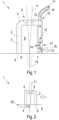
- the device 1 according to the invention is shown in a highly schematic manner, wherein the device 1 has the shielding device 2, wherein the shielding device 2 is designed in a hood-like or bell-shaped manner, with a circumferential side wall 3 and a top wall 4, wherein the circumferential side wall 3 has a free circumferential edge opposite the top wall 4, with which the device 2 stands on a first workpiece 6 and a second workpiece 7.
- the circumferential side wall 3 and the top wall 4 of the welding cover 2 as well as the first workpiece 6 and the second workpiece 7 thus delimit a cavity 8 of the welding cover 2 during operation.
- the ceiling wall 4 there is an opening 9, which is optionally covered on the outside with a laser glass 10 to allow a laser beam 11 to pass through, the laser beam 11 being optionally generated by a laser generator which is arranged on the welding cover 2 (not shown).
- a bore 12 is arranged in the circumferential side wall 3, extending from the top wall 4 toward the circumferential edge 5.
- the bore 12 runs parallel to the longitudinal extent of the circumferential side wall 3.
- the bore 12 has at least one constriction 13 as a Venturi stage, but can also have a plurality of constrictions 13 along its length.
- a transverse bore 14 is provided from the cavity 8, which opens into the bore 12 in the area of the constriction.
- the bore 12 On the upper side, in the area of the top wall 4, the bore 12 has a fluid connection area 15 for receiving a fluid supply hose 16.
- a fluid can be guided through the bore 12 through the fluid supply hose 16 in the direction indicated by the arrows 17, with a Venturi effect being induced in a known manner by the constriction 13.
- This Venturi effect draws gas or air out of the cavity 8 of the welding cover 2 through the transverse bore 14.
- the bore 12 has a fluid outlet 18 which is directed outwards slightly away from the circumferential edge 5.
- the welding cover 2 of the device 1 is guided so that the laser beam is directed onto the welding joint 19 between the first workpiece 6 and the second workpiece 7.
- a plurality of bores 12 are provided, wherein, for example, the bores 12 are supplied with fluid via an annular channel (not shown) in the top wall 4, wherein a corresponding fluid connection region 15 of the annular channel is correspondingly provided for receiving a fluid supply hose 16.
- an annular channel not shown
- a corresponding fluid connection region 15 of the annular channel is correspondingly provided for receiving a fluid supply hose 16.
- a plurality of brush packs in particular metallic brush packs (not shown), are preferably provided, which extend the circumferential side wall 3 and preferably terminate with the circumferential edge 5, so that they rest snugly on a weld seam and are deflected by it, guiding them along it during movement.
- brush packs lamellae or sealing lips made of a heat-resistant material, in particular a metal foil or a thin metal sheet, or a heat-resistant plastic, such as PTFE, may also be provided.
- the bores 12 can be supplied with a gas as the fluid.
- the welding cover 2 is particularly small and therefore heats up considerably, it is also conceivable to flow a coolant as the fluid through the bores, which likewise brings about the Venturi effect and a water flow vacuum pump effect because the cooling may be even more intensive. In this case, the escaping coolant is collected and recirculated.
- a block element 24 is arranged on an edge in a form-fitting manner and is flush with the edge, so that the welding cover 2 rests positively on the peripheral edge 5 on all sides beyond the edge, so that the vacuum can be maintained.
- a block element 24 can be arranged on the edge with corresponding clamping elements.
- Dovetail guides are milled in and the block element 24 is formed with corresponding dovetails so that the block element is arranged firmly and form-fittingly on the edge.
- Another advantage here is that the dovetail arrangement fixes the blocks to be welded to one another particularly well.
- the welding process is ended, the vacuum is also released by turning off the flow and the welding cover 2 is removed.
- the block element 24 is then moved by removing it from the dovetail guides and inserting it into corresponding dovetail guides on the other edge.
- the welding process is then started by replacing the welding cover accordingly, pulling the vacuum and, if necessary, also moving the welding cover at a small distance from the edge and thus the laser begins welding.
- the short distance from the edge at which the welding is started or stopped is unproblematic, as the welding of such blocks involves very deep welds, ensuring sufficient overlap. If necessary, these very small areas, which are not particularly deep due to the 90° offset of the welds, can be rewelded by hand.
- the distances between the dovetail guides are preferably always the same, so that the block element 24 preferably has dovetails on one side which correspond to one distance of one edge, the other edge having dovetails at a different distance, so that the dovetail guides of the edges are not at the same height.
- the dovetail guides can also have the same distance but be offset by a certain amount, in which case the block element 24 is selected to be so large that even with such an offset the welding cover 2 is reliably covered from below with the block element 24.
- an automated device is used which is arranged on one or both sides of the welding cover 2.
- This covering device 25 has an automatically actuated extension block.
- the extension block 26 is automatically pivoted downwards by means of a guide structure or a guide slot at the moment when there is no longer any workpiece 6, 7 underneath it.
- Two slots for example, control the movement and an actuating element, for example a pneumatic or hydraulic cylinder 27, actuates the extension block 26.
- Control cams 27 of the actuating element 28 and the extension block 26 are preferably arranged on a support structure 29, which in turn is arranged on the device 1.
- slots 30 are arranged in the area of the circumferential side wall 3 at the bottom, wherein the slots or the slot, for example, describes the semicircular arc, so that the front half of the circumferential edge is provided with a slot.
- an extendable and adhesive cushion 31 which is particularly extendable by inflation and which lies against the side wall of the workpieces 6, 7 and adheres there, while the welding cover 2 with the circumferential side wall 3 or the circumferential edge 5 is moved beyond the edge.
- the cushion 31 is designed in particular as an inflatable seal which is so elastic that it can adhere to the workpieces accordingly.
- the expansion of the cushion 31 or the inflatable seal 31 only occurs when the corresponding section of the peripheral edge 5 moves over the edge.
- the seal preferably moves inwards automatically ( Figure 4 Center), as this is the lowest energy state. Increased stiffness at the tip of the seal increases the tendency to move inward.
- the welding cover is designed to be somewhat larger, so that the welding cover as a whole is box-shaped or is arranged within a box-like arrangement 32.
- the box-like arrangement has the passage opening for the laser beam on the underside, which is limited by the circumferential edge 5.
- the box-like arrangement has a flat Bottom wall 33, wherein in the flat bottom wall 33, leading in the direction of movement, a movable plate is arranged which closes off the bottom wall 33 and which, when the opening delimited by the circumferential edge 5 comes into the region of the edge, is moved with the corresponding edge finally over the opening, thus ensuring that no vacuum leak occurs.
- a through groove 35 is provided, which is located in the bottom wall 33 so that a corresponding weld seam can be guided therein.
- a plate-like element is also guided in the through groove 35, which is able to protrude into the opening delimited by the circumferential edge 5 in order to ensure vacuum tightness in the region of the edge when the welding process is started.
- the movable plate 34 and the plate-like element 36 are only displaced in the area of the edge and are otherwise located outside the circumferential edge 5 in order to be protected from the welding heat.
- a movable vacuum chamber 38 is carried below the welding cover 2 on the other side of the welding joint in order to prevent gas from being introduced into the cavity 8 by the welding joint and to ensure improved weld seam quality.
- the vacuum chamber 38 can be designed essentially like the welding cover 2 or slightly larger, wherein the vacuum is preferably generated according to the same principle.
- the cavity when blocks are welded which are later to be assembled to form a larger cavity, the cavity can already be assembled from the non-welded blocks, fixed to one another and then the entire cavity can be placed under vacuum, so that when welding from the outside, gas is sucked in through the possibly not entirely tight weld joints and in the area of the weld cover the cavity 8 can be more easily subjected to vacuum and in addition the weld seam quality can be improved in this area by the gas being evacuated from the weld joint immediately before welding.
Landscapes
- Engineering & Computer Science (AREA)
- Physics & Mathematics (AREA)
- Optics & Photonics (AREA)
- Plasma & Fusion (AREA)
- Mechanical Engineering (AREA)
- Laser Beam Processing (AREA)
- Arc Welding In General (AREA)
Claims (24)
- Dispositif de soudage sous vide, présentant un couvercle de soudage (2) en forme de cloche ou de capot avec une paroi latérale périphérique (3) et un espace creux (8) délimité par celle-ci, un bord libre périphérique (5) étant présent, avec lequel le couvercle de soudage (2) peut être posé sur une surface plane, de sorte que l'espace creux (8) est fermé par la surface plane et la paroi périphérique (3) et éventuellement une paroi de recouvrement (4),
caractérisé en ce qu'il est prévu dans la paroi latérale périphérique au moins un agencement avec un alésage (12) avec une zone de raccordement (15) pour une amenée de fluide et une sortie de fluide (18), une constriction (13) étant prévu dans l'alésage (12) afin de créer un effet Venturi et un alésage transversal (14) étant en outre prévu de l'espace creux (8) dans l'alésage (12) pour aspirer du gaz de l'espace creux (8) par l'effet Venturi à travers l'alésage transversal (14) pour produire une dépression. - Dispositif selon la revendication 1, caractérisé en ce qu'une pluralité d'agencements sont prévus avec l'alésage (12) dans la paroi latérale périphérique.
- Dispositif selon la revendication 1 ou 2, caractérisé en ce que la pluralité d'agencements est alimentée en fluide par un canal annulaire et le canal annulaire dispose d'une ou de plusieurs zones d'alimentation en fluide (15).
- Dispositif selon l'une des revendications précédentes, caractérisé en ce que les sorties de fluide (18) dudit au moins un agencement débouchent dans un deuxième canal annulaire dans lequel le fluide est collecté et évacué par une ou plusieurs sorties.
- Dispositif selon l'une des revendications précédentes, caractérisé en ce que, dans la zone d'un cordon de soudure prévu, la paroi latérale périphérique (3) est prolongée vers l'extérieur par une saillie (20), un tunnel de passage (21) pour un cordon de soudure étant prévu dans la zone d'un joint de soudure (19).
- Dispositif selon la revendication 5, caractérisé en ce que le tunnel de passage (21) a une largeur qui est suffisamment large pour qu'un cordon de soudure habituellement généré par laser puisse y passer.
- Dispositif selon la revendication 5 ou 6, caractérisé en ce qu'un alésage (12) s'étend au-dessus du tunnel de passage (21), l'alésage (12) s'étendant au-dessus du tunnel de passage (21) parallèlement au tunnel de passage (21) vers l'extérieur, de sorte que le tunnel de passage (21) peut être refroidi par le fluide s'écoulant à travers l'alésage.
- Dispositif selon l'une des revendications 5 à 7, caractérisé en ce qu'à l'intérieur du tunnel de passage (21) sont prévus un ou plusieurs paquets de brosses, en particulier des paquets de brosses métalliques, qui prolongent la paroi latérale périphérique (3), se terminent de préférence avec le bord périphérique (5), de sorte que ceux-ci reposent sur un cordon de soudure et sont déviés par celui-ci et sont guidés le long du cordon de soudure lors d'un mouvement du couvercle de soudage (2).
- Dispositif selon l'une des revendications 5 à 8, caractérisé en ce qu'en plus ou à la place de paquets de brosses, il y a des lamelles ou des lèvres d'étanchéité en un matériau résistant à la chaleur, en particulier une feuille métallique ou une tôle métallique mince ou une matière plastique résistant à la chaleur, comme le PTFE, les paquets de brosses et les lamelles ou les lèvres d'étanchéité étant disposés en alternance ou successivement.
- Dispositif selon l'une des revendications 5 à 9, caractérisé en ce que, dans la zone d'une voûte de tunnel (22) du tunnel de passage (21), il est prévu un ou plusieurs alésages transversaux (14) débouchant dans l'alésage (12), avec respectivement une constriction de Venturi (13) interagissant, afin d'aspirer des gaz s'écoulant à travers le tunnel de passage (21) de l'extérieur vers l'espace creux (8) et de refroidir simultanément cette zone de manière intensive.
- Dispositif selon l'une des revendications précédentes, caractérisé en ce que, pour le soudage à proximité immédiate des bords des pièces à souder (6, 7), il existe un dispositif de recouvrement automatisé (25) qui est disposé sur un côté ou sur les deux côtés du couvercle de soudage (2), le dispositif de recouvrement (25) possède un bloc d'extension (26) pouvant être actionné automatiquement et qui, lorsque le couvercle de soudage (2) atteint le bord, est amené par pivotement jusqu'au bord correspondant et y est maintenu pendant que le couvercle de soudage (2) glisse sur ce bloc d'extension (26),
le bloc d'extension (26) étant automatiquement pivoté vers le bas au moyen d'une structure de guidage ou d'une coulisse de guidage au moment où il n'y a plus de pièce à usiner (6, 7) sous lui, deux cames de commande (27) commandant par exemple le mouvement et un élément d'actionnement, par exemple un vérin pneumatique ou hydraulique (28), actionnant le bloc d'extension (26), les cames de commande (27), l'élément d'actionnement (28) et le bloc d'extension (26) étant disposés sur une structure de support (29) qui est à son tour disposée sur le dispositif (1). - Dispositif selon l'une des revendications précédentes, caractérisé en ce que dans la zone de la paroi latérale périphérique (3), des fentes (30) sont disposées en bas à partir du bord périphérique (5) et s'étendent depuis le bord périphérique (5) dans la paroi périphérique (3), les fentes ou la fente (30) décrivant par exemple un arc semi-circulaire, de sorte que la moitié avant du bord périphérique (5) dans le sens de déplacement est pourvu d'une fente (30), un coussin (31) ou un joint d'étanchéité (31) pouvant être déployé et adhérant, en particulier par gonflage, reposant dans la fente, lequel s'applique contre la paroi latérale des pièces à usiner (6, 7) et y adhère, tandis que le couvercle de soudage (2) est déplacé au-delà du bord avec la paroi latérale périphérique (3) ou le bord périphérique (5).
- Dispositif selon l'une des revendications 1 à 11, caractérisé en ce que le couvercle de soudage est réalisé en forme de caisson ou est disposé à l'intérieur d'un agencement en forme de caisson (32), l'agencement en forme de caisson (32) possédant sur sa face inférieure une ouverture de passage (37) pour le faisceau laser (11), qui est délimitée par le bord périphérique (5), l'agencement en forme de caisson (32) présentant une paroi de fond plane (33), une plaque mobile (34) étant disposée dans la paroi de fond plane (33) en avance dans le sens de déplacement et se terminant par la paroi de fond (33), qui, lorsque l'ouverture (37) délimitée par le bord périphérique (5) arrive dans la zone de le bord, peut être déplacée avec le bord correspondant se terminant au-dessus de l'ouverture (37), de sorte qu'il est garanti qu'aucune fuite de vide ne se produit, une rainure de passage (35) étant prévue sur le côté opposé de l'ouverture, laquelle se trouve dans la paroi de fond (33), de sorte qu'un cordon de soudure correspondant peut y être guidé, un élément en forme de plaque (36) est également guidé dans la rainure de passage (35) et est capable de faire saillie dans l'ouverture (37) délimitée par le bord périphérique (5) afin d'assurer l'étanchéité au vide dans la zone du bord lorsque le procédé de soudage est lancé, la plaque mobile (34) et l'élément en forme de plaque (36) ne sont déplacés que dans la zone du bord et se trouvent sinon à l'extérieur du bord périphérique (5) afin d'être protégés de la chaleur de soudage.
- Procédé de soudage sous vide au moyen d'un laser, dans lequel un dispositif selon l'une des revendications précédentes est guidé le long d'un joint de soudure (19) entre une première pièce à usiner (6) et une deuxième pièce à usiner (7) et, dans la zone du joint de soudure (19), un faisceau laser (11) fait fondre les pièces à usiner (6, 7) et les relie ainsi l'une à l'autre.
- Procédé selon la revendication 14, caractérisé en ce que les alésages (12)n du dispositif (1) sont traversés par un gaz ou un liquide.
- Procédé selon la revendication 14 ou 15, caractérisé en ce que le liquide amené est reçu à la sortie de fluide (18) et est en particulier évacué.
- Procédé selon l'une des revendications 14 à 16, caractérisé en ce que, pour le soudage de corps creux, en particulier en aluminium, on fait le vide dans le corps creux pendant l'opération de soudage jusqu'à une dépression souhaitée, de sorte que le joint de soudure (19) dans la zone du couvercle de soudage soutient la dépression ou qu'aucun gaz provenant de l'espace intérieur du corps creux n'est attiré dans le couvercle de soudage (2) par la dépression dans celui-ci.
- Procédé selon l'une des revendications 14 à 16, caractérisé en ce qu'une chambre à dépression mobile (38) est entraînée sous le couvercle de soudage (2), de l'autre côté du joint de soudure (19), afin d'empêcher que du gaz ne soit amené dans l'espace creux (8) par le joint de soudage et afin d'assurer une meilleure qualité de la soudure.
- Procédé selon l'une des revendications 14 à 16, caractérisé en ce que, sur un bord commun des pièces à usiner (6, 7) qui doit être dépassé par le dispositif (1) pour le soudage, un élément de bloc (24) est disposé par complémentarité de forme et en se terminant avec le bord, de sorte que le couvercle de soudage (2) repose par complémentarité de forme de tous côtés avec le bord périphérique (5) au-delà du bord, de sorte que le vide peut être maintenu.
- Procédé selon la revendication 19, caractérisé en ce que l'élément de bloc (24) est disposé sur le bord avec des éléments de serrage correspondants et/ou des guides en queue d'aronde sont par exemple fraisés ou disposés d'une autre manière sur le côté du joint de soudure (19) et l'élément de bloc (24) est formé avec des queues d'aronde correspondantes, de sorte que l'élément de bloc (24) est disposé de manière fixe, par complémentarité de forme et de manière définitive sur le bord.
- Procédé selon la revendication 19 ou 20, caractérisé en ce que, après que la soudure est terminée, le vide est également supprimé par l'arrêt de l'écoulement et le couvercle de soudage (2) est retiré, puis l'élément de bloc (24) est déplacé, en le retirant des guides en queue d'aronde et en l'insérant dans des guides en queue d'aronde correspondants de l'autre côté du bord, puis en commençant le processus de soudage en remettant en place le couvercle de soudage (2) de manière correspondante, en tirant le vide et, le cas échéant, en commençant également le mouvement du couvercle de soudage (2) à une faible distance du bord, et donc le laser avec le soudage.
- Procédé selon l'une quelconque des revendications 19 à 21, caractérisé en ce que les espacements des guides en queue d'aronde sont disposés de manière égale, de sorte que l'élément de bloc (24) possède de préférence sur un côté des queues d'aronde correspondant à l'un des espacements des guides en queue d'aronde sur un côté du bord, l'autre côté du bord possédant des queues d'aronde à un espacement différent, de sorte que les guides en queue d'aronde des bords ne sont pas situés à la même hauteur.
- Procédé selon l'une des revendications 19 à 21, caractérisé en ce que les guides en queue d'aronde présentent un même écartement, mais sont décalés d'une certaine valeur sur les côtés respectifs du bord, l'élément de bloc (24) étant alors choisi suffisamment grand pour que, même avec un tel décalage, le couvercle de soudage (2) soit recouvert de manière fiable par le dessous par l'élément de bloc (24).
- Procédé selon l'une des revendications 19 à 23, caractérisé en ce que les guidages en queue d'aronde dans les pièces à usiner (6, 7) sont fermés par des pièces d'ajustage une fois le soudage terminé.
Applications Claiming Priority (2)
| Application Number | Priority Date | Filing Date | Title |
|---|---|---|---|
| DE102021107422.3A DE102021107422A1 (de) | 2021-03-24 | 2021-03-24 | Vorrichtung und Verfahren zum Schweißen |
| PCT/EP2022/057517 WO2022200367A2 (fr) | 2021-03-24 | 2022-03-22 | Dispositif et procédé de soudage |
Publications (3)
| Publication Number | Publication Date |
|---|---|
| EP4313471A2 EP4313471A2 (fr) | 2024-02-07 |
| EP4313471B1 true EP4313471B1 (fr) | 2025-05-28 |
| EP4313471C0 EP4313471C0 (fr) | 2025-05-28 |
Family
ID=81346669
Family Applications (1)
| Application Number | Title | Priority Date | Filing Date |
|---|---|---|---|
| EP22717756.5A Active EP4313471B1 (fr) | 2021-03-24 | 2022-03-22 | Dispositif et procédé de soudage sous vide, avec une constriction afin de créer un effet venturi |
Country Status (3)
| Country | Link |
|---|---|
| EP (1) | EP4313471B1 (fr) |
| DE (1) | DE102021107422A1 (fr) |
| WO (1) | WO2022200367A2 (fr) |
Families Citing this family (3)
| Publication number | Priority date | Publication date | Assignee | Title |
|---|---|---|---|---|
| CN118357572B (zh) * | 2024-06-18 | 2024-12-31 | 江苏正力新能电池技术股份有限公司 | 激光焊接冷却装置 |
| CN118720534B (zh) * | 2024-06-27 | 2024-12-10 | 南通国星消防器材有限公司 | 一种用于铝制品焊接装置 |
| CN119703357B (zh) * | 2024-12-30 | 2025-07-25 | 广东东方绿能新能源有限公司 | 一种锂电池组生产用激光焊接装置 |
Family Cites Families (9)
| Publication number | Priority date | Publication date | Assignee | Title |
|---|---|---|---|---|
| US3609287A (en) | 1970-01-22 | 1971-09-28 | Smith Corp A O | Method and apparatus for electron beam welding |
| FR2609591B1 (fr) * | 1987-01-13 | 1990-12-07 | Soudure Autogene Francaise | Coiffe pour torche de travail a l'arc et torche correspondante |
| NZ272635A (en) | 1994-08-02 | 1998-02-26 | Mcneil Ppc Inc | Laser cutting/drilling processing head that creates a vortex gas flow within the head to clean and prevent back spatting of particles onto the lens therein |
| DE102008027322A1 (de) | 2008-06-07 | 2009-12-10 | Forschungszentrum Jülich GmbH | Druckstufensystem für eine Vorrichtung zum Elektronenstrahlschweißen und Verfahren zum Elektronenstrahlschweißen |
| JP6037741B2 (ja) | 2012-09-18 | 2016-12-07 | 三菱重工工作機械株式会社 | 移動型真空溶接装置 |
| DE102014103635C5 (de) | 2014-03-17 | 2019-12-19 | RWTH Aachen - Körperschaft des öffentlichen Rechts | Unterdruckkammer mit einem Schutzgehäuse |
| DE102014210838A1 (de) | 2014-06-06 | 2015-12-17 | Trumpf Laser Gmbh | Einkoppeloptik, Laserschweißkopf und Laserschweißvorrichtung mit Vakuumkammer |
| JP6852572B2 (ja) | 2017-06-01 | 2021-03-31 | トヨタ自動車株式会社 | レーザ溶接装置 |
| DE102019200189A1 (de) * | 2019-01-09 | 2020-07-09 | Thyssenkrupp Ag | Laserstrahlreinigungsdüse und Verfahren zum Laserreinigen |
-
2021
- 2021-03-24 DE DE102021107422.3A patent/DE102021107422A1/de active Pending
-
2022
- 2022-03-22 WO PCT/EP2022/057517 patent/WO2022200367A2/fr not_active Ceased
- 2022-03-22 EP EP22717756.5A patent/EP4313471B1/fr active Active
Also Published As
| Publication number | Publication date |
|---|---|
| WO2022200367A2 (fr) | 2022-09-29 |
| EP4313471C0 (fr) | 2025-05-28 |
| WO2022200367A3 (fr) | 2022-11-24 |
| DE102021107422A1 (de) | 2022-09-29 |
| EP4313471A2 (fr) | 2024-02-07 |
Similar Documents
| Publication | Publication Date | Title |
|---|---|---|
| EP4313471B1 (fr) | Dispositif et procédé de soudage sous vide, avec une constriction afin de créer un effet venturi | |
| DE102010052206B4 (de) | Vorrichtung zum Herstellen von dreidimensionalen Objekten | |
| DE19537924C2 (de) | Verfahren zum Kühlen des Schweißnahtbereichs beim Laserschweißen und Vorrichtung zum Durchführen dieses Verfahrens | |
| WO2019115140A1 (fr) | Appareil pour l'alimentation en gaz de protection, le chauffage et l'alimentation en poudre ainsi que dispositif et procédé pour la fabrication additive de pièces et pièce | |
| DE19739975C2 (de) | Verfahren zur Herstellung einer Laminatstruktur | |
| DE102014209161A1 (de) | Steuereinheit, Vorrichtung und Verfahren zum Herstellen eines dreidimensionalen Objekts | |
| WO2020104202A1 (fr) | Flux radial sur une base de construction | |
| EP3328619B1 (fr) | Procédé et dispositif de fabrication d'un objet tridimensionnel | |
| EP3720633B1 (fr) | Dispositif de fabrication multicouche pour la fabrication additive d'au moins une partie d'un composant et son procédé de fonctionnement | |
| DE102009033896A1 (de) | Durchlaufschweißmaschine | |
| DE4210518A1 (de) | Kopf für Laserfräs- und -graviermaschinen für die Bearbeitung von im wesentlichen plattenförmigem Gut | |
| DE202017106063U1 (de) | Kontaktschweißheizkomponente und Schweißautomat | |
| DE2250936A1 (de) | Verfahren und vorrichtung zum aufeinanderfolgenden schweissen von werkstuecken mittels elektronenstrahlen | |
| WO2007028404A1 (fr) | Dispositif destine a recevoir des materiaux sous forme de plaques pour au moins un processus de separation | |
| DE1615395A1 (de) | Verfahren zum Schweissen von Werkstuecken mittels gebuendelter Elektronenstrahlen und Elektronenstrahlschweissmaschine zur Durchfuehrung des Verfahrens | |
| EP1518633A1 (fr) | Procédé de soudage, article assemblé et l'utilisation d'un laser pour produire l'article assemblé | |
| DE102006047794A1 (de) | Laseranordnung zur Bearbeitung der Oberfläche eines Werkstücks | |
| WO2020043419A1 (fr) | Dispositif de construction par couches destiné à la fabrication additive d'au moins une zone d'élément structural d'un élément structural, procédé destiné à faire fonctionner un tel dispositif de construction par couches et support d'enregistrement | |
| DE102009052220A1 (de) | Verfahren zum Herstellen einer Schweißnaht mittels eines Energiestrahls | |
| DE2239764A1 (de) | Verfahren zur herstellung von geschweissten rohren und vorrichtung zur durchfuehrung des verfahrens | |
| DE19541899A1 (de) | Vorrichtung zum Spannen und Laserstrahlschweißen von Dünnblechen | |
| DE4016414C1 (en) | Appts. for prodn. of large plastic container(s) with planar walls - includes transport rail for weld extruder, carriage running parallel to weld, and adjustable carrier on carriage etc. | |
| EP2277654A1 (fr) | Procédé et dispositif de protection contre les projections lors du soudage de pièces usinées creuses | |
| DE102004026427B4 (de) | Verwendung einer Vorrichtung zur Behandlung eines Substrates mittels Laserstrahlen und Vorrichtung zur Behandlung des Substrates | |
| DE2748789A1 (de) | Verfahren und vorrichtung zum thermochemischen flaemmen |
Legal Events
| Date | Code | Title | Description |
|---|---|---|---|
| STAA | Information on the status of an ep patent application or granted ep patent |
Free format text: STATUS: UNKNOWN |
|
| STAA | Information on the status of an ep patent application or granted ep patent |
Free format text: STATUS: THE INTERNATIONAL PUBLICATION HAS BEEN MADE |
|
| PUAI | Public reference made under article 153(3) epc to a published international application that has entered the european phase |
Free format text: ORIGINAL CODE: 0009012 |
|
| STAA | Information on the status of an ep patent application or granted ep patent |
Free format text: STATUS: REQUEST FOR EXAMINATION WAS MADE |
|
| 17P | Request for examination filed |
Effective date: 20230830 |
|
| AK | Designated contracting states |
Kind code of ref document: A2 Designated state(s): AL AT BE BG CH CY CZ DE DK EE ES FI FR GB GR HR HU IE IS IT LI LT LU LV MC MK MT NL NO PL PT RO RS SE SI SK SM TR |
|
| DAV | Request for validation of the european patent (deleted) | ||
| DAX | Request for extension of the european patent (deleted) | ||
| GRAP | Despatch of communication of intention to grant a patent |
Free format text: ORIGINAL CODE: EPIDOSNIGR1 |
|
| STAA | Information on the status of an ep patent application or granted ep patent |
Free format text: STATUS: GRANT OF PATENT IS INTENDED |
|
| INTG | Intention to grant announced |
Effective date: 20241217 |
|
| GRAS | Grant fee paid |
Free format text: ORIGINAL CODE: EPIDOSNIGR3 |
|
| GRAA | (expected) grant |
Free format text: ORIGINAL CODE: 0009210 |
|
| STAA | Information on the status of an ep patent application or granted ep patent |
Free format text: STATUS: THE PATENT HAS BEEN GRANTED |
|
| AK | Designated contracting states |
Kind code of ref document: B1 Designated state(s): AL AT BE BG CH CY CZ DE DK EE ES FI FR GB GR HR HU IE IS IT LI LT LU LV MC MK MT NL NO PL PT RO RS SE SI SK SM TR |
|
| REG | Reference to a national code |
Ref country code: GB Ref legal event code: FG4D Free format text: NOT ENGLISH |
|
| REG | Reference to a national code |
Ref country code: CH Ref legal event code: EP |
|
| REG | Reference to a national code |
Ref country code: IE Ref legal event code: FG4D Free format text: LANGUAGE OF EP DOCUMENT: GERMAN Ref country code: DE Ref legal event code: R096 Ref document number: 502022004076 Country of ref document: DE |
|
| U01 | Request for unitary effect filed |
Effective date: 20250625 |
|
| U07 | Unitary effect registered |
Designated state(s): AT BE BG DE DK EE FI FR IT LT LU LV MT NL PT RO SE SI Effective date: 20250702 |
|
| PG25 | Lapsed in a contracting state [announced via postgrant information from national office to epo] |
Ref country code: ES Free format text: LAPSE BECAUSE OF FAILURE TO SUBMIT A TRANSLATION OF THE DESCRIPTION OR TO PAY THE FEE WITHIN THE PRESCRIBED TIME-LIMIT Effective date: 20250528 |
|
| PG25 | Lapsed in a contracting state [announced via postgrant information from national office to epo] |
Ref country code: GR Free format text: LAPSE BECAUSE OF FAILURE TO SUBMIT A TRANSLATION OF THE DESCRIPTION OR TO PAY THE FEE WITHIN THE PRESCRIBED TIME-LIMIT Effective date: 20250829 Ref country code: NO Free format text: LAPSE BECAUSE OF FAILURE TO SUBMIT A TRANSLATION OF THE DESCRIPTION OR TO PAY THE FEE WITHIN THE PRESCRIBED TIME-LIMIT Effective date: 20250828 |
|
| PG25 | Lapsed in a contracting state [announced via postgrant information from national office to epo] |
Ref country code: PL Free format text: LAPSE BECAUSE OF FAILURE TO SUBMIT A TRANSLATION OF THE DESCRIPTION OR TO PAY THE FEE WITHIN THE PRESCRIBED TIME-LIMIT Effective date: 20250528 |
|
| PG25 | Lapsed in a contracting state [announced via postgrant information from national office to epo] |
Ref country code: HR Free format text: LAPSE BECAUSE OF FAILURE TO SUBMIT A TRANSLATION OF THE DESCRIPTION OR TO PAY THE FEE WITHIN THE PRESCRIBED TIME-LIMIT Effective date: 20250528 |
|
| PG25 | Lapsed in a contracting state [announced via postgrant information from national office to epo] |
Ref country code: RS Free format text: LAPSE BECAUSE OF FAILURE TO SUBMIT A TRANSLATION OF THE DESCRIPTION OR TO PAY THE FEE WITHIN THE PRESCRIBED TIME-LIMIT Effective date: 20250828 |
|
| PG25 | Lapsed in a contracting state [announced via postgrant information from national office to epo] |
Ref country code: IS Free format text: LAPSE BECAUSE OF FAILURE TO SUBMIT A TRANSLATION OF THE DESCRIPTION OR TO PAY THE FEE WITHIN THE PRESCRIBED TIME-LIMIT Effective date: 20250928 |
|
| PG25 | Lapsed in a contracting state [announced via postgrant information from national office to epo] |
Ref country code: SM Free format text: LAPSE BECAUSE OF FAILURE TO SUBMIT A TRANSLATION OF THE DESCRIPTION OR TO PAY THE FEE WITHIN THE PRESCRIBED TIME-LIMIT Effective date: 20250528 |
|
| PG25 | Lapsed in a contracting state [announced via postgrant information from national office to epo] |
Ref country code: CZ Free format text: LAPSE BECAUSE OF FAILURE TO SUBMIT A TRANSLATION OF THE DESCRIPTION OR TO PAY THE FEE WITHIN THE PRESCRIBED TIME-LIMIT Effective date: 20250528 |
|
| PG25 | Lapsed in a contracting state [announced via postgrant information from national office to epo] |
Ref country code: SK Free format text: LAPSE BECAUSE OF FAILURE TO SUBMIT A TRANSLATION OF THE DESCRIPTION OR TO PAY THE FEE WITHIN THE PRESCRIBED TIME-LIMIT Effective date: 20250528 |
|
| PLBE | No opposition filed within time limit |
Free format text: ORIGINAL CODE: 0009261 |
|
| STAA | Information on the status of an ep patent application or granted ep patent |
Free format text: STATUS: NO OPPOSITION FILED WITHIN TIME LIMIT |
|
| REG | Reference to a national code |
Ref country code: CH Ref legal event code: L10 Free format text: ST27 STATUS EVENT CODE: U-0-0-L10-L00 (AS PROVIDED BY THE NATIONAL OFFICE) Effective date: 20260409 |
|
| U20 | Renewal fee for the european patent with unitary effect paid |
Year of fee payment: 5 Effective date: 20260312 |