EP4315821B1 - Procédé d'ajustement des paramètres d'imprimante d'une imprimante numérique - Google Patents
Procédé d'ajustement des paramètres d'imprimante d'une imprimante numérique Download PDFInfo
- Publication number
- EP4315821B1 EP4315821B1 EP22719840.5A EP22719840A EP4315821B1 EP 4315821 B1 EP4315821 B1 EP 4315821B1 EP 22719840 A EP22719840 A EP 22719840A EP 4315821 B1 EP4315821 B1 EP 4315821B1
- Authority
- EP
- European Patent Office
- Prior art keywords
- printer
- digital
- tonal
- hyperspectral
- data
- Prior art date
- Legal status (The legal status is an assumption and is not a legal conclusion. Google has not performed a legal analysis and makes no representation as to the accuracy of the status listed.)
- Active
Links
Images
Classifications
-
- H—ELECTRICITY
- H04—ELECTRIC COMMUNICATION TECHNIQUE
- H04N—PICTORIAL COMMUNICATION, e.g. TELEVISION
- H04N1/00—Scanning, transmission or reproduction of documents or the like, e.g. facsimile transmission; Details thereof
- H04N1/46—Colour picture communication systems
- H04N1/56—Processing of colour picture signals
- H04N1/60—Colour correction or control
- H04N1/603—Colour correction or control controlled by characteristics of the picture signal generator or the picture reproducer
- H04N1/6033—Colour correction or control controlled by characteristics of the picture signal generator or the picture reproducer using test pattern analysis
- H04N1/6036—Colour correction or control controlled by characteristics of the picture signal generator or the picture reproducer using test pattern analysis involving periodic tests or tests during use of the machine
-
- H—ELECTRICITY
- H04—ELECTRIC COMMUNICATION TECHNIQUE
- H04N—PICTORIAL COMMUNICATION, e.g. TELEVISION
- H04N1/00—Scanning, transmission or reproduction of documents or the like, e.g. facsimile transmission; Details thereof
- H04N1/46—Colour picture communication systems
- H04N1/56—Processing of colour picture signals
- H04N1/60—Colour correction or control
- H04N1/6097—Colour correction or control depending on the characteristics of the output medium, e.g. glossy paper, matt paper, transparency or fabrics
Definitions
- Colour is an essential feature of a printed decoration, which is created using various techniques, such as gravure or digital printing. In each of these techniques, the desired appearance of the print is achieved by overlaying different pigment layers of the basic colours.
- the gravure printing process is a printing technique in which the elements to be reproduced are present as depressions in a printing form, e.g. a printing roller, which is inked before printing.
- the printing ink is primarily located in the depressions and is pressed into the print surface by the pressure of the printing form and by adhesive forces onto the object to be printed.
- digital printing however, the print image is transferred directly from a computer to a digital printer, such as a laser printer or inkjet printer, whereby the use of static printing forms is not necessary.
- An open problem that represents a central theme in all areas of the ink-based or ink-processing industry is the achievement of a high degree of color fidelity, in other words the ability to reproduce specified colors with minimal chromatic difference in relation to an original, especially on different substrates or printing materials.
- a key step in this regard is, among other things, ensuring continuous control of print quality throughout the entire printing process.
- a central quality requirement for all printing processes is that color deviations between a master sample of a design and subsequent prints of the same Decors only occur below a specified target value.
- print quality refers to how well a print of a decor matches the original pattern. The greater the match, the higher the print quality.
- the printer used for printing has a significant influence on print quality. It is well known that in the printers used in the digital printing industry, several print heads are arranged in a row, each one being "responsible” for printing a specific section of a design. It is also known that the printing behavior of the individual print heads, and thus their print quality, changes over time. Print behavior refers to the printing characteristics of a print head, i.e., the density, print intensity, and color strength of the printed image. These printing characteristics can change irregularly over time.
- the printing behavior of a printer's print heads must be monitored and, if necessary, calibrated and/or adjusted.
- State-of-the-art technology requires that various tonal values of the printing media, such as the CMRK printing inks, be output as so-called tonal value patches in a tonal value target and measured using optical measuring methods or manual dot measurements with a densitometer. These measured values are then used to influence, change, adjust, and/or control the print head software or the software that processes the print files and/or separation data.
- the tonal value field is then measured point-by-point at a location that exhibits such a color deviation, an incorrect tonal value will be determined for this tonal value field. For example, a dark point or a bright, luminous point could be measured in a tonal value field that has a very light yellow. In both cases, a tonal value for the tonal value field would be determined that is not representative of this tonal value field. This would result in incorrect corrections or adjustments in the printing process.
- the DE 10 2017 202 031 A1 deals with the correction of color deviations in digital printing machines.
- the goal of the process is to enable true-to-color reproduction of a digital print template during the printing process.
- a test sample is measured using a colorimeter. Using colorimeters results in a point-by-point measurement of the test sample, with the associated disadvantages.
- the EP 3 020 565 B1 deals with a process for producing color- and detail-accurate reproductions of a printed decoration using various printing techniques.
- the object of the process is to produce decorative prints on substrates with a comparable quality appearance, regardless of whether the decoration was printed digitally or analogically.
- the WO 2014/154302 A1 discloses a method for calibrating a printer, which comprises measuring current colorimetric parameters of a printed calibration pattern, comparing these parameters with a corresponding reference measurement, and determining a current linearization based on this comparison.
- the object of the invention is to provide a method with which the print quality in a printing process can be increased and the disadvantages of the prior art can be eliminated.
- a digital tonal value target with 1 to n tonal value patches is created and saved using suitable software, where n ⁇ N.
- the tonal value patches of the tonal value target comprise at least some of the color components of the color system used for printing.
- Color systems frequently used in digital printing include, for example, the CYMK color system, the CRYK color system, or 1-color, 5-color, 6-color, 7-color, or 8-color color systems.
- the CRYK color system refers to a color system with the color components cyan, red, yellow, and black.
- the tonal value target has tonal value fields for all color components of the color system used, with tonal value fields with several different tonal values being present for each color component.
- the digital tonal target is printed onto a first carrier material under first printing conditions with first printer parameters by a first digital printer.
- At least the area of a tonal value field of a tonal value target that is covered by a printer head during printing is measured hyperspectrally.
- hyperspectral area measurement is understood to mean that part of the area of a tonal value field of a tonal value target is measured hyperspectrally.
- at least the area of a tonal value field of a tonal value target that is covered by a printer head during printing is measured hyperspectrally.
- at least one area of a tonal value target with a width between 0.01 mm and 50 mm and a length between 1 mm and 50 mm is therefore measured hyperspectrally.
- the width is to be understood as the direction corresponding to the printing width of the digital printer, and the length as the direction corresponding to the printing length, i.e. the direction in which the carrier material passes through the digital printer.
- ACMS ® Advanced Colour Measurement System
- Hyperspectral systems have a large number of detectors. The recording results in a hyperspectral data cube with two spatial and one spectral dimension. Four basic techniques are available for generating this hyperspectral data cube. With a so-called snapshot, the entire data set is delivered with a single detector output. In spatial scanning, each detector output delivers the spectrum of a narrow strip of the original. In spectral scanning, each detector output delivers a monochromatic, spatial map of the original. In spatial-spectral scanning, each detector output delivers a spectrally encoded, spatial map of the original.
- Well-known systems are the hyperspectral area measuring devices ACMS ® and ICMS ® from IPAC, whereby the ACMS ® is used offline in the printing process and the ICMS ® is used inline in the printing process.
- Hyperspectral area measurement has the advantage that a sample is measured using hyperspectral area measurement, and then an average of the measured data is calculated. This average of the measured data is representative of the hyperspectrally measured sample. The entire sample can be measured section by section using hyperspectral area measurement, with an average of the corresponding data being calculated for each section. The individual Sections are adjacent to each other but do not overlap.
- the method according to the invention can be used to hyperspectrally measure part of the area of a tonal value field or the entire area of a tonal value field, with an average value being calculated from the measured data. This average value is then representative of the measured tonal value field.
- mean values of the hyperspectral data are formed, assigned to different areas of tonal value fields of a tonal value target, wherein the different areas of the tonal value fields of a tonal value target are each covered by a printer head during printing.
- a mean value is thus determined for different areas of the tonal value fields, wherein each of these areas of the tonal value fields was printed by a printer head of the digital printer.
- the mean values for the different areas of the tonal value fields of the tonal value target are therefore each assigned to the printer head that printed the respective area of the tonal value field.
- the average values can be calculated not only for the printer heads, but even for the individual nozzles of the printer heads. This makes it possible to adjust printer parameters that affect individual nozzles of the printer heads, for example, controlling the electrical voltage of individual printer nozzles.
- the L*, a*, and b* values in the so-called L*a*b* color space are determined as colorimetric data from the data of the hyperspectral area measurement.
- the L*a*b* color space is a color space that covers the range of perceivable colors.
- the L*a*b* color space is described by a three-dimensional coordinate system.
- the L* axis describes the brightness (luminance) of the color with values from 0 (black) to 100 (white).
- the a* axis describes the green or red component of a color, with negative values representing green and positive values representing red.
- the b* axis describes the blue or yellow component of a color, with negative values representing blue and positive values representing yellow.
- a digital reference pattern comprising the colorimetric data and/or the color density values assigned to the area of the tonal value field that was used to form the at least one mean value of the hyperspectral data.
- a digital reference pattern is created comprising the colorimetric data and/or the color density values assigned to the areas of the tonal value fields used to form the mean values of the hyperspectral data.
- colorimetric data and/or color density values are created for one or more tonal value patches, assigned to at least one printer head or multiple printer heads of the digital printer.
- colorimetric data and/or color density values are created for each printer head for each of the 1 to n tonal value patches of a tonal value target.
- the method according to the invention therefore has the particular advantage that the tonal values of a printed tonal target are not only recorded point-by-point, as with methods known from the prior art, but rather a surface measurement is performed.
- averages are calculated from the measurement data of the hyperspectrally measured area, which then represent the tonal value of a region of the tonal value field. Inaccuracies due to inhomogeneous coloring of the printed tonal value field can thus be avoided. This significantly increases the accuracy in determining the tonal value of a region of the tonal value field.
- a hyperspectral area measuring device is used to measure the printed tonal value target, rather than a purely optical system. Due to the parameters of the chips and sensors used, optical measuring systems offer only limited options for capturing tonal values. A hyperspectral area measuring device captures significantly more measurement data, thereby increasing the data quality for subsequent process steps. As already described, the purely optical system operates without hyperspectral measurement and thus with sensors and chips designed for this type of measurement. The chips and sensors used for hyperspectral measurement, on the other hand, are specifically designed for this type of measurement technology.
- the digital tonal target is output onto a second carrier material under second printing conditions with second printer parameters by the first digital printer or a second digital printer.
- the digital reference pattern and the digital pattern are compared with each other and at least one similarity value is determined.
- the comparison can be carried out automatically using software or manually by a user. Suitable software for the automated execution of the comparison, such as Such comparisons, for example, are known to those skilled in the art, such as the Colorgate software from the company of the same name or software from IPAC Improve Process Analytics and Control GmbH. These compare the colorimetric data and/or color density values that can be assigned to the same area of a tonal value patch and thus to the same printer head(s). This means that the measurement data of two tonal value patches or of areas within two tonal value patches with identical positions in the tonal value target are compared.
- the measurement data are preferably determined to at least 4 decimal places and compared with the corresponding accuracy.
- the digital reference pattern and the digital pattern contain colorimetric data, in one embodiment these are directly compared with each other. If the colorimetric data are L*a*b* values, an L* value of the digital reference pattern and an L* value of the digital pattern are compared with each other. The same applies to the a* and b* values. The comparison thus reveals any deviation in one of the colorimetric values, in particular one of the L*a*b* values. In this embodiment, this deviation represents the similarity value and can be specified in absolute numbers or as a percentage. Both values can be converted into one another using simple mathematical operations. In this embodiment, the results of the comparisons represent the similarity value for the area of the tonal value field on which the averaging of the hyperspectral data is based.
- the calculated color distances each represent the similarity value for the area of the tonal field underlying the averaging of the hyperspectral data
- the digital reference pattern and the digital pattern contain color density values, in one embodiment these are directly compared with each other.
- the comparison thus reveals any deviation of one of the color density values of the digital pattern from a color density value of the digital reference pattern. This deviation can be specified in absolute numbers or as a percentage. Both values can be converted into each other using simple mathematical operations.
- the results of the comparisons each represent the similarity value for the area of the tonal value field underlying the averaging of the hyperspectral data.
- similarity indices can also be output when comparing the digital reference pattern with the digital pattern.
- the similarity index represents the deviation between two measured values. The higher the similarity index, the less the measured values being compared deviate from each other.
- the similarity comparison is performed by software on a computing unit. If the ACMS® method is used for hyperspectral area measurement, the similarity comparison can advantageously be performed using the similarity index of the associated software. This application is known to those skilled in the art.
- the colorimetric data in particular the L*a*b* values and/or the color density values, are also compared.
- a similarity index of 100% means that there are no deviations between an L*a*b* value of the digital reference sample and the digital sample, and both are identical to each other.
- the tonal value fields of the tonal value target output in process step g) can, for various reasons, have a higher or lower tonal value printed on the carrier material.
- the at least one similarity index represents the at least one similarity value.
- the comparison can also be performed manually by a user, based on the user's experience. The user can then initiate further actions based on the comparison result.
- the tolerance range is determined based on the quality requirements of the respective printing process and the colors it contains, and can therefore be flexibly adapted to specific needs. This allows a customer's individual print quality requirements for a print job to be taken into account.
- a tolerance range is specified for all tonal value fields.
- different tolerance ranges are specified for different tonal value fields. The latter embodiment allows for the fact that a viewer does not perceive differences in color with the same sensitivity for every tonal value level.
- the adjustment of at least one printer parameter or a combination of several printer parameters of the first or second digital printer can be carried out automatically or manually.
- a separation file is created at the beginning of the printing process, in which the decoration is broken down into the basic colors to be printed.
- the separation data is generated for the color system used in the print, such as the CMYK color system, from the decoration's print file.
- CMYK color system CMYK color system
- software creates print data for each color component of the color system, which is then assigned to the print heads. Print data for each color component of the color system used for a decor is called separation data.
- both the separation data are adjusted and the electrical voltage at the print head is controlled. Changing the separation data using software can be used to adjust the tonal values very evenly. This can be done with precision down to just a few pixels during printing. At the same time, by controlling the electrical voltage at the print head, a coarser adjustment can be made or the density of the ink application during printing can be changed for the entire controllable area of the print head.
- a portion of the unprinted substrate can be measured hyperspectrally, and the measured values of the unprinted substrate are then assigned a tonal value level of 0%.
- suitable software can then be used to calculate out the influence of the color of the substrate material on the measurement results of the hyperspectral measurement of the tonal value patches of the tonal value target.
- the absolute density values thus obtained can, for example, advantageously be compared with measured values from a measurement using a densitometer.
- a portion of the unprinted substrate is therefore also measured hyperspectrally.
- the first printing conditions and the second printing conditions as well as the first and second carrier materials are the same in the process according to the invention.
- This embodiment makes it possible to To carry out a quality check in a printing process that lasts for a long time.
- Process steps g) to m) are carried out at a time interval from process steps a) to f).
- the tonal value target is output onto the second carrier material by the first printer with which the tonal value target was also output onto the first carrier material.
- This embodiment makes it possible to carry out a quality check of a printer over a predetermined period of time. Changes in print quality are immediately detected when the digital sample is compared with the digital reference sample. If at least one similarity value lies outside a predetermined tolerance range, this can be counteracted by adjusting a printer parameter or a combination of printer parameters.
- method steps g) to m) are repeated after a predetermined time.
- the print quality of a printer can be monitored hourly or daily. Changes in print quality are immediately detected when the digital sample is compared with the digital reference sample. Should at least one similarity value lie outside the predetermined tolerance range, this can be counteracted by adjusting a printer parameter or a combination of printer parameters.
- the tonal value target is printed onto a substrate during decorative printing.
- the tonal value target can be printed onto the substrate in one or both edge areas during decorative printing. If this is done at intervals or continuously, a Deviations in the tonal values of the tonal fields can be immediately determined, and appropriate adjustments can be made. Even if only print heads near the edge of the substrate can be monitored, any color drift occurring during the printing process can be quickly detected. This design thus serves as a continuous quality control tool during the printing process.
- the tonal value target is printed onto a first carrier material using a first digital printer and onto a second carrier material using a second digital printer.
- the printer parameters of the second digital printer are then preferably adjusted such that the at least one similarity value lies within a predetermined tolerance range. This makes it possible to adapt the print quality of the second digital printer to that of the first digital printer.
- the tonal values output by the second digital printer when printing the tonal value target are thus calibrated to the tonal values output by the first digital printer when printing the tonal value target.
- the first and second digital printers can then print decorations with the same quality onto the type of carrier material used for calibration, whereby the printing conditions must also be constant. This calibration can be repeated repeatedly during the printing process, thereby simultaneously performing quality control.
- an additional tonal value target is optionally created and printed onto a substrate using a first or second digital printer.
- the tonal value target comprises tonal fields that extend across the entire width of the substrate. Different tonal values of a color component are arranged one behind the other along the print length.
- the additional tonal value target has the same tonal values of the color components as the tonal value target created in process step a).
- the printer parameters, printing conditions, and the substrate used are the same as in process steps b) and g).
- the step of printing a further tonal value target onto a carrier material using a first or second digital printer is omitted, with each tonal value field of the tonal value target being printed across the entire width of the carrier material.
- At least one image of the tonal target output in method step g) or in method step n) is recorded with an optical camera system.
- the optical camera system can comprise one or more individual cameras. If multiple individual cameras are used, their individual images are preferably combined into an overall image using suitable software.
- the overall image can thus comprise the image from one camera or the combined individual images from multiple individual cameras.
- the at least one image or the overall image preferably depicts all of the tonal value fields of the tonal value target that were output. In a further embodiment, the at least one image or the overall image depicts only a portion of the tonal value fields of the tonal value target that were output.
- each tonal value field of the tonal value target or of the further tonal value target in this embodiment comprises the entire width of the carrier material. Different tonal value fields are then arranged one behind the other in the print length. According to the invention, several regions of the tonal value field can therefore be evaluated for one tonal value field. The individual regions preferably border one another but do not overlap. Particularly preferably, the size of each region corresponds to the area covered by a printer head during printing. In this embodiment, colorimetric data of the tonal value field can then be assigned to each printer head. This makes it possible to check the print quality of each printer head in the printer used. Ideally, the colorimetric data should be identical for each region of a tonal value field.
- L* values are calculated from the overall image for each area of a tonal value field that can be assigned to a printer head.
- Software suitable for calculating L* values from an image captured with an optical camera is known from the prior art.
- Calibration factors are then calculated from the L* values from at least one image and the L* values of the digital reference pattern by comparing the L* values of identical print head areas. Two calibration factors are then compared, and a similarity value is calculated from their deviation. To calculate the similarity value, a A calibration factor is used as a reference, which is assumed to be correct. For this purpose, the calibration factor calculated for the L* values of the printer heads already adjusted in process steps a) to m) is used. All other calibration factors within a tonal value field are compared with this calibration factor, and a similarity value is determined. The similarity value is preferably specified in %. If the similarity value lies outside a specified tolerance range, at least one printer parameter or a combination of printer parameters is adjusted.
- the tolerance range in this embodiment is preferably specified in %.
- the tolerance range is between 0% and ⁇ 5%, preferably between 0% and ⁇ 3%, particularly preferably between 0% and ⁇ 0.5%. Since a deviation can occur in both a positive and a negative direction, the tolerance range is specified as a ⁇ range.
- an L* value is calculated from the at least one image or the overall image for each area of a tonal value field that can be assigned to a printer head using suitable software.
- Calibration factors can then be calculated from the L* values of the digital reference pattern and the L* values of the at least one image.
- the calibration factors are calculated for each individual area of the tonal value field that can be assigned to a printer head.
- a calibration factor must serve as a reference that is assumed to be correct.
- the calibration factor calculated for the L* values of the printer heads already adjusted in method steps a) to m) is used. All other calibration factors within a tonal value field are each compared with this calibration factor, and a similarity value is determined. If the similarity value lies outside a specified tolerance range, at least one printer parameter or a combination of printer parameters is adjusted.
- This embodiment combines the advantages of hyperspectral area measurement with an optical camera system.
- the printer parameters can then be adjusted across the entire area of the substrate, with the hyperspectral data serving to calibrate the data from the optical camera system.
- the tonal value target from process step a) is a tonal value target which has tonal value fields that extend across the entire width of the carrier material. Different tonal values of a color component are then arranged one behind the other in the print length.
- the tonal value target is applied to the carrier material and hyperspectrally measured in the edge area. From the hyperspectral measurement, a digital reference pattern is created which has L* values. The tonal value target is again applied to a carrier material and the same area is again hyperspectrally measured. From these measured values, a digital pattern is created which also has L* values.
- At least one image of the tonal target printed in process step g) is captured with an optical camera system.
- the at least one image or an overall image depicts the entire tonal target.
- an L* value is calculated from the at least one image or the overall image for each area of a tonal value field that can be assigned to a printer head using suitable software.
- Calibration factors can then be calculated from the L* values of the digital reference pattern and the L* values of the at least one image.
- the calibration factors are calculated for each individual area of the tonal value field that can be assigned to a printer head.
- a calibration factor must serve as a reference that is assumed to be correct.
- the calibration factor calculated for the L* values of the printer heads already adjusted in process steps a) to m) is used. All other calibration factors within a tonal value field are each compared with this calibration factor, and a similarity value is determined. If the similarity value lies outside a specified tolerance range, at least one printer parameter or a combination of printer parameters is adjusted. This allows all printer heads to be adjusted even though not the entire tonal value target was hyperspectrally measured.
- the device comprises a hyperspectral area measuring device. Suitable devices have already been described.
- the device optionally comprises at least one means for further processing the decoration printed on a carrier material.
- Such a means for further processing is preferably selected from the group comprising an impregnation device, a device for pressing the printed carrier material with further layers, such as an impregnation layer, and a device for profiling the printed carrier material.
- the pressing means is a short-cycle press (KT press).
- the profiling means is also a short-cycle press.
- the short-cycle press used for pressing is also used for profiling.
- the device comprises several means for further processing a decoration printed on a carrier material. This can be a combination of the previously mentioned means for further processing a decoration printed on a carrier material.
- the computing unit is, for example, a suitable PC or process computer, which is preferably integrated into the device.
- the computing unit can also be not integrated into the device and thus be located externally.
- the device has an interface for the computing unit.
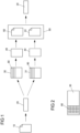
- Figure 2 represents an embodiment of a printed tonal value target in which the tonal value fields 80 of the tonal value target are applied only in the edge region of the carrier material 30.
- Example 1 Offline - manual hyperspectral area measurement and adjustment of the separation data using software
- the individual tonal value fields were each 10x10 mm in size, and the tonal value fields of the individual color components were arranged next to each other in the print width.
- the arrangement of the tonal value fields corresponds to the Figure 2 These were measured offline with a hyperspectral area measuring device, and for each of the 160 tonal fields, an L*, a*, and b* value was calculated and saved. Paper was used as the carrier material.
- a digital reference pattern was created from the averaged reference values of the 160 tonal value patches, which included, among other things, L*a*b* values for each tonal value patch.
- the tonal target was printed again on the 4-color CRYK digital paper printing system with a print width of 210 cm, between a substrate width of 50 cm and a substrate width of 54 cm.
- the substrate type and printing conditions remained the same.
- the printed tonal targets were measured hyperspectrally, and images were captured across the entire print width of all tonal fields using the optical camera system.
- a digital sample was created from the measured data each day, which was compared with the digital reference sample. A tolerance range of ⁇ 2% was specified.
- the measurement revealed a deviation in the digital sample compared to the digital reference sample.
- the comparison revealed a b* value that was 1.4 times higher for all tonal value levels starting at the 60% tonal value level. This resulted in a similarity value of 4% for the corresponding b* values. These similarity values were thus outside the tolerance range of ⁇ 2%. This is reflected in the printed image as a yellow tint.
- the tonal target was then printed once again on the 4-color CRYK paper digital printing system with a print width of 210 cm between a width of 50 cm and a width of 54 cm of the carrier material.
- Software filters were used for the separation data.
- the substrate type remained unchanged, as did the printing conditions.
- the output tonal targets were again measured hyperspectrally.
- a digital sample was created from the measured data, which was compared with the digital reference sample. No deviations were detected between the digital sample and the digital reference sample. The similarity value was 0% for all tonal patches, thus within the tolerance range.
- the tonal fields of the additional tonal target had a width that corresponded to the width of the substrate. All 40 tonal fields for each color component were printed one after the other on the substrate along the entire print length.
- the printing system had an optical camera system that captured images across the entire print width of all tonal fields.
- the camera system comprised four individual cameras, each of which captured one image.
- a composite image was then created from the four individual images per line, depicting the entire width of the substrate. This means that 160 lines (with each line containing a gradation of the tonal values of each color component of the CRYK color system) were printed and recorded along the print length.
- all print heads or their individual sections could be assigned to the printed tonal fields in 10-pixel units.
- an L* value was calculated from the optical image.
- Each L* value was compared with the L* value for that tonal value level from the digital reference pattern, and a calibration factor was generated.
- the calibration factors for a tonal value level were compared with a reference value, and a similarity value was determined for each.
- the reference value used was the calibration factor calculated for the L* values of the print heads already adjusted in the previous process steps a) to m). All other calibration factors within a tonal value field were each compared with this calibration factor, and a similarity value was determined for each.
- Example 2 Inline hyperspectral area measurement and adjustment of the separation data using software
- a tonal value target was created for a CRYK color system.
- the tonal value target comprised 40 tonal value patches with graduated tonal values for each color component.
- the tonal values of consecutive tonal value patches of a color component each differed by 2.5% in tonal value.
- Each tonal value patch had a length of 15 mm in the direction of the print length, and the individual tonal value patches were printed one behind the other in the direction of the print length. All tonal value patches of the tonal value target were output. Paper was used as the substrate.
- the tonal target was printed again the next day on the 4-color CRYK paper digital printing press, using the same substrate type, the same printing conditions, and the same printer parameters.
- the tonal patches were again measured inline with the traversing hyperspectral area measuring device.
- the same division of the tonal patches into individual areas was used for evaluation as in the creation of the digital reference sample.
- L*a*b* values were calculated from the measured values, and a digital sample was created, which was compared with the digital reference sample.
- Example 3 Hyperspectral area measurement inline and combination of adjustment of the separation data using software and control of the electrical voltage of the print heads
- the tonal target contained a tonal patch for each color component, each with a tonal value of 100%.
- the tonal patches of the four color components of the CRYK color system were each printed across the entire width of the substrate and measured with a traversing hyperspectral colorimeter. The measurement range was 15 mm in print length and 1 mm in print width, with the recorded data being averaged.
- the traverse was divided into four areas where the hyperspectral area measurement device recorded the measurement data.
- L*a*b* values were calculated from the measurement data and a digital reference pattern was created.
- the substrate material corresponded to the substrate used in the decorative printing.
- the tonal target was printed again on a substrate by the 4-color CRYK paper digital printing system.
- the same substrate type was used, and the printing conditions and printer parameters remained unchanged.
- the tonal patches of the 4 color components of the CRYK color system were measured using a traversing hyperspectral colorimeter. The measurement range was 15 mm in print length and 1 mm in print width, with the acquired data being averaged. L*a*b* values were calculated, and a digital sample was created, which was compared to the digital reference sample. For each tonal patch, several similarity values were determined, which were assigned to the individual print heads. A tolerance range of ⁇ 2% was specified.
- Example 3 the process described in Example 3 was performed. However, since only larger areas or entire print heads can be uniformly adjusted using electrical voltage, the process described in Example 2 was performed in a second step. The result was a homogeneous output across the print width of all tonal values in the print. This process can be performed regularly, manually or fully automatically, to ensure quality control in printing processes.
- the ink batch for the cyan color component was replaced.
- the new batch is lighter in tone value than the old one.
- the detected difference was corrected by adjusting at least one printer parameter or a combination of printer parameters. This made it possible to compensate for deviations in tonal value caused by a new batch of ink.
- the process was carried out analogously to the method described in Example 6, with the digital reference pattern being created based on the printing of a tonal value target on the old paper batch, and the digital pattern based on the printing of a tonal value target on the new paper batch. Based on the detected deviation, the electrical voltage of all print head areas was increased, which corrected the lack of intensity in the tonal values and enabled color-accurate printing of decorations in a subsequent printing process.
- a tonal value target was created for a CRYK color system.
- the tonal value target comprised 40 tonal value patches with graduated tonal values for each color component.
- the tonal values of consecutive tonal value patches of a color component each differed by 2.5% in tonal value.
- Each tonal value patch had a length of 15 mm in the direction of the print length, and the individual tonal value patches were printed one behind the other in the direction of the print length. Paper was used as the substrate.
- the tonal value patches were measured inline using a traversing hyperspectral area measuring device.
- a 0.3 mm print width was assigned to a print head or separation data area. The entire width of a tonal value patch was thus divided into several individual areas.
- hyperspectral averages were recorded from the individual areas in the 0.3 x 15 mm format.
- L*a*b* values were calculated from the measured data, and a digital reference pattern was created. A tolerance range of ⁇ 2% was specified.
Landscapes
- Engineering & Computer Science (AREA)
- Multimedia (AREA)
- Signal Processing (AREA)
- Spectrometry And Color Measurement (AREA)
- Accessory Devices And Overall Control Thereof (AREA)
Claims (15)
- Procédé permettant l'ajustement des paramètres d'imprimante et/ou des données de séparation d'une imprimante numérique, présentant les étapes consistant àa) créer et stocker une cible de valeur de ton numérique comportant 1 à n champs de valeur de ton, dans lequel n e N ;b) distribuer la cible de valeur de ton sur un premier matériau de support dans de premières conditions d'impression comportant de premiers paramètres d'imprimante par une première imprimante numérique ;c) mesurer de manière hyperspectrale en planimétrie au moins une partie de la cible de valeur de ton distribuée à l'étape b), dans lequel au moins la surface de la cible de valeur de ton qui est recouverte par une tête d'impression dans l'impression est mesurée de manière hyperspectrale et dans lequel des données dont les gammes de longueurs d'onde sont contiguës les unes aux autres sont enregistrées lors de la mesure hyperspectrale en planimétrie ;d) former au moins une valeur moyenne des données hyperspectrales associées à une région d'un champ de valeur de ton d'une cible de valeur de ton recouverte par une tête d'impression dans l'impression ;e) calculer des données colorimétriques et/ou des valeurs de densité de couleur à partir de l'au moins une valeur moyenne des données hyperspectrales ;f) créer un motif de référence numérique présentant au moins les données colorimétriques et/ou les valeurs de densité de couleur associées à la région du champ de valeur de ton utilisée pour la formation de l'au moins une valeur moyenne des données hyperspectrales ;g) distribuer la cible de valeur de ton numérique sur un second matériau de support dans de secondes conditions d'impression comportant de seconds paramètres d'imprimante par la première imprimante numérique ou par une seconde imprimante numérique ;h) mesurer de manière hyperspectrale en planimétrie au moins une partie de la cible de valeur de ton distribuée à l'étape g), dans lequel au moins la surface de la cible de valeur de ton qui est recouverte par une tête d'impression dans l'impression est mesurée de manière hyperspectrale et dans lequel des données dont les gammes de longueurs d'onde sont contiguës les unes aux autres sont enregistrées lors de la mesure hyperspectrale en planimétrie ;i) former au moins une valeur moyenne des données hyperspectrales associées à une région d'un champ de valeur de ton d'une cible de valeur de ton recouverte par une tête d'impression dans l'impression ;j) calculer des données colorimétriques et/ou des valeurs de densité de couleur à partir de l'au moins une valeur moyenne des données hyperspectrales ;k) créer un motif numérique présentant au moins les données colorimétriques et/ou les valeurs de densité de couleur associées à la région du champ de valeur de ton utilisée pour la formation de l'au moins une valeur moyenne des données hyperspectrales ;l) comparer le motif de référence numérique au motif numérique et déterminer au moins une valeur de similitude ; etm) ajuster au moins un paramètre d'imprimante et/ou les données de séparation ou une combinaison de plusieurs paramètres d'imprimante ou une combinaison de plusieurs paramètres d'imprimante et les données de séparation de la première ou de la seconde imprimante numérique si l'au moins une valeur de similitude est en dehors d'au moins une plage de tolérance prédéfinie, dans lequel les paramètres d'imprimante sont choisis dans le groupe présentant une tension électrique dans la tête d'impression, commande logicielle de l'imprimante et température.
- Procédé selon la revendication 1, caractérisé en ce que les premières conditions d'impression et les secondes conditions d'impression, ainsi que le premier et le second matériau de support, sont identiques.
- Procédé selon l'une des revendications précédentes, caractérisé en ce que• aux étapes de procédé d) et i), des valeurs moyennes des données hyperspectrales associées à différentes régions de champs de valeur de ton d'une cible de valeur de ton sont formées, dans lequel les différentes régions des champs de valeur de ton d'une cible de valeur de ton sont respectivement couvertes par une tête d'impression dans l'impression ;• aux étapes de procédé e) et j), des données colorimétriques et/ou des valeurs de densité de couleur sont calculées à partir de chaque valeur moyenne des données hyperspectrales ;• à l'étape de procédé f), un motif de référence numérique est créé, lequel présente les données colorimétriques et/ou les valeurs de densité de couleur associées aux régions des champs de valeur de ton qui ont été utilisées pour la formation des valeurs moyennes des données hyperspectrales ; et• à l'étape de procédé k), un motif numérique est créé, lequel présente les données colorimétriques et/ou les valeurs de densité de couleur associées aux régions des champs de valeur de ton qui ont été utilisées pour la formation des valeurs moyennes des données hyperspectrales.
- Procédé selon l'une des revendications précédentes, caractérisé en ce que la comparaison du motif de référence numérique au motif numérique à l'étape de procédé l) est effectuée de manière manuelle ou automatisée.
- Procédé selon l'une des revendications précédentes, caractérisé en ce que l'au moins une valeur de similitude est présente en tant que déviation entre des données colorimétriques, en particulier des valeurs L*a*b* et/ou en tant que déviations entre des valeurs de densité de couleur et/ou en tant qu'écart de couleur ΔE et/ou en tant qu'indice de similitude.
- Procédé selon l'une des revendications précédentes, caractérisé en ce que l'ajustement d'au moins un paramètre d'imprimante ou d'une combinaison de plusieurs paramètres d'imprimante de la première ou de la seconde imprimante numérique est effectué de manière automatique ou manuelle.
- Procédé selon l'une des revendications précédentes, caractérisé en ce que les étapes de procédé g) à m) sont exécutées autant de fois que la valeur de similitude se situe à l'intérieur d'au moins une plage de tolérance prédéfinie.
- Procédé selon l'une des revendications précédentes, caractérisé en ce que les étapes de procédé g) à m) sont répétées après un temps prédéfini.
- Procédé selon l'une des revendications précédentes, caractérisé en ce que le matériau de support est choisi dans le groupe présentant du papier, verre, métal, films, panneaux en matériau dérivé du bois, en particulier panneaux MDF ou HDF,
panneaux CBP, contreplacages, couches de vernis, panneaux en matière plastique et panneaux de support inorganiques. - Procédé selon l'une des revendications précédentes, caractérisé en ce qu'un décor est imprimé sur le second matériau de support outre la cible de valeur de ton, dans lequel le décor est imprimé sur le second matériau de support avec la même imprimante numérique que la cible de valeur de ton.
- Procédé selon l'une des revendications précédentes, caractérisé en ce que, en outre, après l'ajustement d'au moins un paramètre d'imprimante ou d'une combinaison de plusieurs paramètres d'imprimante, un décor est imprimé sur le second matériau de support, dans lequel le décor est imprimé sur le second matériau de support avec la même imprimante numérique que la cible de valeur de ton.
- Procédé selon l'une des revendications précédentes, caractérisé en ce que le procédé est intégré en ligne dans un processus d'impression ou est réalisé hors ligne.
- Procédé selon l'une des revendications précédentes, caractérisé en ce que le procédé comprend en outre les étapes consistant àn) éventuellement, créer et distribuer une autre cible de valeur de ton sur un matériau de support avec une première ou une seconde imprimante numérique, dans lequel chaque champ de valeur de ton de la cible de valeur de ton est distribué sur toute la largeur du matériau de support ;o) capturer au moins une image de la cible de valeur de ton distribuée à l'étape de procédé g) ou à l'étape de procédé n) avec un système formant caméra optique ;p) calculer les valeurs L* pour chaque région d'un champ de valeur de ton à partir de l'au moins une image qui peut être associée à une tête d'impression ;q) calculer des facteurs d'étalonnage avec les valeurs L* provenant de l'au moins une image et les valeurs L* du motif de référence numérique ;r) comparer les facteurs d'étalonnage et calculer au moins une valeur de similitude ; ets) ajuster au moins un paramètre d'imprimante ou une combinaison de plusieurs paramètres d'imprimante de la première ou de la seconde imprimante numérique si l'au moins une valeur de similitude est en dehors d'au moins une plage de tolérance prédéfinie.
- Dispositif, en particulier installation d'impression, configuré pour réaliser un procédé permettant l'ajustement des paramètres d'imprimante et/ou des données de séparation d'une imprimante numérique selon l'une des revendications 1 à 13, dans lequel le dispositif présente• au moins un appareil formant planimètre hyperspectral ;• au moins une unité de calcul ;• au moins une première imprimante numérique permettant d'imprimer une cible de valeur de ton ;• éventuellement, une seconde imprimante numérique permettant d'imprimer une cible de valeur de ton ; et• éventuellement, au moins un moyen permettant le traitement ultérieur d'un décor imprimé sur un matériau de support.
- Dispositif selon la revendication 14, présentant en outre un système formant caméra optique.
Priority Applications (1)
| Application Number | Priority Date | Filing Date | Title |
|---|---|---|---|
| EP25161867.4A EP4561049A3 (fr) | 2021-03-30 | 2022-03-30 | Procédé d'ajustement des paramètres d'imprimante d'une imprimante numérique |
Applications Claiming Priority (2)
| Application Number | Priority Date | Filing Date | Title |
|---|---|---|---|
| EP21165922.2A EP4068743B1 (fr) | 2021-03-30 | 2021-03-30 | Procédé d'ajustement des paramètres d'imprimante d'une imprimante numérique |
| PCT/EP2022/058387 WO2022207690A1 (fr) | 2021-03-30 | 2022-03-30 | Procédé d'adaptation des paramètres d'impression d'une imprimante numérique |
Related Child Applications (2)
| Application Number | Title | Priority Date | Filing Date |
|---|---|---|---|
| EP25161867.4A Division EP4561049A3 (fr) | 2021-03-30 | 2022-03-30 | Procédé d'ajustement des paramètres d'imprimante d'une imprimante numérique |
| EP25161867.4A Division-Into EP4561049A3 (fr) | 2021-03-30 | 2022-03-30 | Procédé d'ajustement des paramètres d'imprimante d'une imprimante numérique |
Publications (3)
| Publication Number | Publication Date |
|---|---|
| EP4315821A1 EP4315821A1 (fr) | 2024-02-07 |
| EP4315821B1 true EP4315821B1 (fr) | 2025-04-09 |
| EP4315821C0 EP4315821C0 (fr) | 2025-04-09 |
Family
ID=75302331
Family Applications (3)
| Application Number | Title | Priority Date | Filing Date |
|---|---|---|---|
| EP21165922.2A Active EP4068743B1 (fr) | 2021-03-30 | 2021-03-30 | Procédé d'ajustement des paramètres d'imprimante d'une imprimante numérique |
| EP22719840.5A Active EP4315821B1 (fr) | 2021-03-30 | 2022-03-30 | Procédé d'ajustement des paramètres d'imprimante d'une imprimante numérique |
| EP25161867.4A Pending EP4561049A3 (fr) | 2021-03-30 | 2022-03-30 | Procédé d'ajustement des paramètres d'imprimante d'une imprimante numérique |
Family Applications Before (1)
| Application Number | Title | Priority Date | Filing Date |
|---|---|---|---|
| EP21165922.2A Active EP4068743B1 (fr) | 2021-03-30 | 2021-03-30 | Procédé d'ajustement des paramètres d'imprimante d'une imprimante numérique |
Family Applications After (1)
| Application Number | Title | Priority Date | Filing Date |
|---|---|---|---|
| EP25161867.4A Pending EP4561049A3 (fr) | 2021-03-30 | 2022-03-30 | Procédé d'ajustement des paramètres d'imprimante d'une imprimante numérique |
Country Status (6)
| Country | Link |
|---|---|
| US (1) | US12126780B2 (fr) |
| EP (3) | EP4068743B1 (fr) |
| CN (1) | CN117099362A (fr) |
| ES (2) | ES3032855T3 (fr) |
| PL (2) | PL4068743T3 (fr) |
| WO (1) | WO2022207690A1 (fr) |
Families Citing this family (4)
| Publication number | Priority date | Publication date | Assignee | Title |
|---|---|---|---|---|
| EP3961166A1 (fr) * | 2020-08-24 | 2022-03-02 | Swiss Krono TEC AG | Procédé d'impression d'un décor et dispositif correspondant |
| EP4383694A1 (fr) * | 2022-12-06 | 2024-06-12 | Unilin, BV | Un procédé de fabrication d'une feuille décorative et un procédé de fabrication d'un panneau décoratif comprenant une feuille décorative |
| EP4645846A1 (fr) * | 2024-04-30 | 2025-11-05 | SWISS KRONO Tec AG | Procédé et dispositif d'impression d'un décor à imprimer |
| EP4679809A1 (fr) * | 2024-07-11 | 2026-01-14 | Unilin, BV | Procédé d'impression d'une image en couleur sur un substrat |
Family Cites Families (8)
| Publication number | Priority date | Publication date | Assignee | Title |
|---|---|---|---|---|
| US8259369B2 (en) * | 2005-06-30 | 2012-09-04 | Xerox Corporation | Color characterization or calibration targets with noise-dependent patch size or number |
| US9375963B2 (en) | 2013-03-28 | 2016-06-28 | Hewlett-Packard Development Company, L.P. | Printer calibration |
| PL3020565T3 (pl) | 2014-11-14 | 2017-04-28 | Flooring Technologies Ltd. | Sposób wytwarzania przynajmniej jednego drukowanego dekoru do stosowania w przynajmniej dwóch różnych metodach druku i urządzenie do realizacji tego sposobu |
| CN107181892B (zh) | 2016-03-11 | 2020-01-17 | 海德堡印刷机械股份公司 | 数字印刷机中颜色偏差的修正 |
| US10768497B2 (en) * | 2016-10-03 | 2020-09-08 | Xerox Corporation | Hyperspectral imaging system |
| HUE052890T2 (hu) * | 2018-06-06 | 2021-05-28 | Flooring Technologies Ltd | Eljárás hordozóanyagokon lévõ dekornyomatok online minõségellenõrzésére |
| ES3060627T3 (en) * | 2020-02-20 | 2026-03-27 | Flooring Technologies Ltd | Method for transferring analog templates to a decor print |
| EP3961166A1 (fr) * | 2020-08-24 | 2022-03-02 | Swiss Krono TEC AG | Procédé d'impression d'un décor et dispositif correspondant |
-
2021
- 2021-03-30 EP EP21165922.2A patent/EP4068743B1/fr active Active
- 2021-03-30 PL PL21165922.2T patent/PL4068743T3/pl unknown
- 2021-03-30 ES ES21165922T patent/ES3032855T3/es active Active
-
2022
- 2022-03-30 ES ES22719840T patent/ES3026124T3/es active Active
- 2022-03-30 PL PL22719840.5T patent/PL4315821T3/pl unknown
- 2022-03-30 WO PCT/EP2022/058387 patent/WO2022207690A1/fr not_active Ceased
- 2022-03-30 EP EP22719840.5A patent/EP4315821B1/fr active Active
- 2022-03-30 CN CN202280025917.XA patent/CN117099362A/zh active Pending
- 2022-03-30 US US18/284,910 patent/US12126780B2/en active Active
- 2022-03-30 EP EP25161867.4A patent/EP4561049A3/fr active Pending
Also Published As
| Publication number | Publication date |
|---|---|
| WO2022207690A1 (fr) | 2022-10-06 |
| EP4561049A2 (fr) | 2025-05-28 |
| EP4068743C0 (fr) | 2025-04-23 |
| PL4315821T3 (pl) | 2025-08-04 |
| EP4561049A3 (fr) | 2025-07-16 |
| PL4068743T3 (pl) | 2025-10-06 |
| CN117099362A (zh) | 2023-11-21 |
| EP4315821A1 (fr) | 2024-02-07 |
| ES3026124T3 (en) | 2025-06-10 |
| EP4315821C0 (fr) | 2025-04-09 |
| ES3032855T3 (en) | 2025-07-28 |
| US12126780B2 (en) | 2024-10-22 |
| EP4068743A1 (fr) | 2022-10-05 |
| EP4068743B1 (fr) | 2025-04-23 |
| US20240275905A1 (en) | 2024-08-15 |
Similar Documents
| Publication | Publication Date | Title |
|---|---|---|
| EP4315821B1 (fr) | Procédé d'ajustement des paramètres d'imprimante d'une imprimante numérique | |
| EP3578939B1 (fr) | Procédé de contrôle de qualité en ligne de l'impression de décors sur des matériaux supports | |
| EP0228347B1 (fr) | Procédé de commande de l'alimentation en encre pour une machine à imprimer, dispositif d'impression équipé de manière correspondante et dispositif de mesure pour un tel appareil d'impression | |
| EP2362633B9 (fr) | Procédé de détermination de données de caractérisation d'un processus d'impression | |
| EP0324718A1 (fr) | Procédé et dispositif pour régler l'encre dans une machine à imprimer | |
| DE102015205275B3 (de) | Verfahren zur Korrektur von Abweichungen gemessener Bilddaten | |
| DE3903981A1 (de) | Verfahren zur regelung der farbgebung von druckerzeugnissen | |
| DE102008016538A1 (de) | Überwachung der visuellen Qualität von in Druckprodukten eingebetteten Farbbildern | |
| EP0914945A2 (fr) | Procédé pour régler l'encrage dans une machine d'impression | |
| DE3925011B4 (de) | Verfahren und Anordnung zur Überwachung einer Druckqualität mehrfarbiger Druckvorlagen einer Offset-Druckmaschine | |
| WO2024156674A1 (fr) | Procédé de surveillance en ligne du mode de fonctionnement d'au moins une tête d'impression | |
| DE102011012806A1 (de) | Graubalancekorrektur eines Druckverfahrens | |
| EP1759845B1 (fr) | Procédé de contrôle pour une méthode à imprimer | |
| DE102011075343B4 (de) | Systeme zur Beurteilung eines Produktexemplars am Leitstand einer Druckmaschine | |
| EP3972233B1 (fr) | Procédé de caractérisation automatisée d'un système d'impression en continu | |
| DE102011075340B4 (de) | System zur Beurteilung eines Produktexemplars am Leitstand einer Druckmaschine | |
| DE102011075347B4 (de) | System zur Anzeige einer ein Druckbild einer Druckmaschine simulierenden Druckbildreferenz | |
| EP3939245B1 (fr) | Procédé d'amélioration qualitative d'une image imprimée à jet d'encre | |
| DE102022108751A1 (de) | Verfahren zum Betreiben einer Tintenstrahldruckmaschine zum Erzeugen reproduzierbarer Druckergebnisse | |
| EP0649743B1 (fr) | Procédé pour contrÔler l'apport de couleur dans une presse fonctionnant suivant le procédé de similigravure | |
| EP4622235A1 (fr) | Procédé de surveillance du fonctionnement d'au moins une tête d'impression | |
| EP1033247B1 (fr) | Procédé de controle de l'encrage dans une machine à imprimer | |
| EP4645846A1 (fr) | Procédé et dispositif d'impression d'un décor à imprimer | |
| EP1279502A1 (fr) | Plages de contrôle pour héliogravure | |
| EP4716206A1 (fr) | Procédé de contrôle du fonctionnement fidèle d'au moins une imprimante |
Legal Events
| Date | Code | Title | Description |
|---|---|---|---|
| STAA | Information on the status of an ep patent application or granted ep patent |
Free format text: STATUS: UNKNOWN |
|
| STAA | Information on the status of an ep patent application or granted ep patent |
Free format text: STATUS: THE INTERNATIONAL PUBLICATION HAS BEEN MADE |
|
| PUAI | Public reference made under article 153(3) epc to a published international application that has entered the european phase |
Free format text: ORIGINAL CODE: 0009012 |
|
| STAA | Information on the status of an ep patent application or granted ep patent |
Free format text: STATUS: REQUEST FOR EXAMINATION WAS MADE |
|
| 17P | Request for examination filed |
Effective date: 20231020 |
|
| AK | Designated contracting states |
Kind code of ref document: A1 Designated state(s): AL AT BE BG CH CY CZ DE DK EE ES FI FR GB GR HR HU IE IS IT LI LT LU LV MC MK MT NL NO PL PT RO RS SE SI SK SM TR |
|
| DAV | Request for validation of the european patent (deleted) | ||
| DAX | Request for extension of the european patent (deleted) | ||
| GRAP | Despatch of communication of intention to grant a patent |
Free format text: ORIGINAL CODE: EPIDOSNIGR1 |
|
| STAA | Information on the status of an ep patent application or granted ep patent |
Free format text: STATUS: GRANT OF PATENT IS INTENDED |
|
| INTG | Intention to grant announced |
Effective date: 20241107 |
|
| GRAS | Grant fee paid |
Free format text: ORIGINAL CODE: EPIDOSNIGR3 |
|
| GRAA | (expected) grant |
Free format text: ORIGINAL CODE: 0009210 |
|
| STAA | Information on the status of an ep patent application or granted ep patent |
Free format text: STATUS: THE PATENT HAS BEEN GRANTED |
|
| AK | Designated contracting states |
Kind code of ref document: B1 Designated state(s): AL AT BE BG CH CY CZ DE DK EE ES FI FR GB GR HR HU IE IS IT LI LT LU LV MC MK MT NL NO PL PT RO RS SE SI SK SM TR |
|
| REG | Reference to a national code |
Ref country code: GB Ref legal event code: FG4D Free format text: NOT ENGLISH |
|
| REG | Reference to a national code |
Ref country code: CH Ref legal event code: EP |
|
| REG | Reference to a national code |
Ref country code: DE Ref legal event code: R096 Ref document number: 502022003521 Country of ref document: DE |
|
| REG | Reference to a national code |
Ref country code: IE Ref legal event code: FG4D Free format text: LANGUAGE OF EP DOCUMENT: GERMAN |
|
| REG | Reference to a national code |
Ref country code: ES Ref legal event code: FG2A Ref document number: 3026124 Country of ref document: ES Kind code of ref document: T3 Effective date: 20250610 |
|
| U01 | Request for unitary effect filed |
Effective date: 20250506 |
|
| U07 | Unitary effect registered |
Designated state(s): AT BE BG DE DK EE FI FR IT LT LU LV MT NL PT RO SE SI Effective date: 20250512 |
|
| PG25 | Lapsed in a contracting state [announced via postgrant information from national office to epo] |
Ref country code: NO Free format text: LAPSE BECAUSE OF FAILURE TO SUBMIT A TRANSLATION OF THE DESCRIPTION OR TO PAY THE FEE WITHIN THE PRESCRIBED TIME-LIMIT Effective date: 20250709 Ref country code: GR Free format text: LAPSE BECAUSE OF FAILURE TO SUBMIT A TRANSLATION OF THE DESCRIPTION OR TO PAY THE FEE WITHIN THE PRESCRIBED TIME-LIMIT Effective date: 20250710 |
|
| PG25 | Lapsed in a contracting state [announced via postgrant information from national office to epo] |
Ref country code: HR Free format text: LAPSE BECAUSE OF FAILURE TO SUBMIT A TRANSLATION OF THE DESCRIPTION OR TO PAY THE FEE WITHIN THE PRESCRIBED TIME-LIMIT Effective date: 20250409 |
|
| PG25 | Lapsed in a contracting state [announced via postgrant information from national office to epo] |
Ref country code: RS Free format text: LAPSE BECAUSE OF FAILURE TO SUBMIT A TRANSLATION OF THE DESCRIPTION OR TO PAY THE FEE WITHIN THE PRESCRIBED TIME-LIMIT Effective date: 20250709 |
|
| PG25 | Lapsed in a contracting state [announced via postgrant information from national office to epo] |
Ref country code: IS Free format text: LAPSE BECAUSE OF FAILURE TO SUBMIT A TRANSLATION OF THE DESCRIPTION OR TO PAY THE FEE WITHIN THE PRESCRIBED TIME-LIMIT Effective date: 20250809 |
|
| PG25 | Lapsed in a contracting state [announced via postgrant information from national office to epo] |
Ref country code: SM Free format text: LAPSE BECAUSE OF FAILURE TO SUBMIT A TRANSLATION OF THE DESCRIPTION OR TO PAY THE FEE WITHIN THE PRESCRIBED TIME-LIMIT Effective date: 20250409 |
|
| PG25 | Lapsed in a contracting state [announced via postgrant information from national office to epo] |
Ref country code: CZ Free format text: LAPSE BECAUSE OF FAILURE TO SUBMIT A TRANSLATION OF THE DESCRIPTION OR TO PAY THE FEE WITHIN THE PRESCRIBED TIME-LIMIT Effective date: 20250409 |
|
| PG25 | Lapsed in a contracting state [announced via postgrant information from national office to epo] |
Ref country code: SK Free format text: LAPSE BECAUSE OF FAILURE TO SUBMIT A TRANSLATION OF THE DESCRIPTION OR TO PAY THE FEE WITHIN THE PRESCRIBED TIME-LIMIT Effective date: 20250409 |
|
| PLBE | No opposition filed within time limit |
Free format text: ORIGINAL CODE: 0009261 |
|
| STAA | Information on the status of an ep patent application or granted ep patent |
Free format text: STATUS: NO OPPOSITION FILED WITHIN TIME LIMIT |
|
| REG | Reference to a national code |
Ref country code: CH Ref legal event code: L10 Free format text: ST27 STATUS EVENT CODE: U-0-0-L10-L00 (AS PROVIDED BY THE NATIONAL OFFICE) Effective date: 20260218 |
|
| 26N | No opposition filed |
Effective date: 20260112 |
|
| REG | Reference to a national code |
Ref country code: CH Ref legal event code: U11 Free format text: ST27 STATUS EVENT CODE: U-0-0-U10-U11 (AS PROVIDED BY THE NATIONAL OFFICE) Effective date: 20260401 |
|
| U20 | Renewal fee for the european patent with unitary effect paid |
Year of fee payment: 5 Effective date: 20260227 |
|
| PGFP | Annual fee paid to national office [announced via postgrant information from national office to epo] |
Ref country code: GB Payment date: 20260324 Year of fee payment: 5 |
|
| PGFP | Annual fee paid to national office [announced via postgrant information from national office to epo] |
Ref country code: TR Payment date: 20260325 Year of fee payment: 5 |
|
| PGFP | Annual fee paid to national office [announced via postgrant information from national office to epo] |
Ref country code: PL Payment date: 20260227 Year of fee payment: 5 |