EP4316557A1 - Respirateur d'anesthésie pour la surveillance et la régulation dynamiques de la pression partielle de dioxyde de carbone - Google Patents
Respirateur d'anesthésie pour la surveillance et la régulation dynamiques de la pression partielle de dioxyde de carbone Download PDFInfo
- Publication number
- EP4316557A1 EP4316557A1 EP23792859.3A EP23792859A EP4316557A1 EP 4316557 A1 EP4316557 A1 EP 4316557A1 EP 23792859 A EP23792859 A EP 23792859A EP 4316557 A1 EP4316557 A1 EP 4316557A1
- Authority
- EP
- European Patent Office
- Prior art keywords
- gas supply
- source
- supply branch
- filter
- fixedly connected
- Prior art date
- Legal status (The legal status is an assumption and is not a legal conclusion. Google has not performed a legal analysis and makes no representation as to the accuracy of the status listed.)
- Granted
Links
Images

Classifications
-
- A—HUMAN NECESSITIES
- A61—MEDICAL OR VETERINARY SCIENCE; HYGIENE
- A61M—DEVICES FOR INTRODUCING MEDIA INTO, OR ONTO, THE BODY; DEVICES FOR TRANSDUCING BODY MEDIA OR FOR TAKING MEDIA FROM THE BODY; DEVICES FOR PRODUCING OR ENDING SLEEP OR STUPOR
- A61M16/00—Devices for influencing the respiratory system of patients by gas treatment, e.g. ventilators; Tracheal tubes
- A61M16/01—Devices for influencing the respiratory system of patients by gas treatment, e.g. ventilators; Tracheal tubes specially adapted for anaesthetising
-
- A—HUMAN NECESSITIES
- A61—MEDICAL OR VETERINARY SCIENCE; HYGIENE
- A61M—DEVICES FOR INTRODUCING MEDIA INTO, OR ONTO, THE BODY; DEVICES FOR TRANSDUCING BODY MEDIA OR FOR TAKING MEDIA FROM THE BODY; DEVICES FOR PRODUCING OR ENDING SLEEP OR STUPOR
- A61M16/00—Devices for influencing the respiratory system of patients by gas treatment, e.g. ventilators; Tracheal tubes
- A61M16/0003—Accessories therefor, e.g. sensors, vibrators, negative pressure
-
- A—HUMAN NECESSITIES
- A61—MEDICAL OR VETERINARY SCIENCE; HYGIENE
- A61M—DEVICES FOR INTRODUCING MEDIA INTO, OR ONTO, THE BODY; DEVICES FOR TRANSDUCING BODY MEDIA OR FOR TAKING MEDIA FROM THE BODY; DEVICES FOR PRODUCING OR ENDING SLEEP OR STUPOR
- A61M16/00—Devices for influencing the respiratory system of patients by gas treatment, e.g. ventilators; Tracheal tubes
- A61M16/0051—Devices for influencing the respiratory system of patients by gas treatment, e.g. ventilators; Tracheal tubes with alarm devices
-
- A—HUMAN NECESSITIES
- A61—MEDICAL OR VETERINARY SCIENCE; HYGIENE
- A61M—DEVICES FOR INTRODUCING MEDIA INTO, OR ONTO, THE BODY; DEVICES FOR TRANSDUCING BODY MEDIA OR FOR TAKING MEDIA FROM THE BODY; DEVICES FOR PRODUCING OR ENDING SLEEP OR STUPOR
- A61M16/00—Devices for influencing the respiratory system of patients by gas treatment, e.g. ventilators; Tracheal tubes
- A61M16/0087—Environmental safety or protection means, e.g. preventing explosion
- A61M16/009—Removing used or expired gases or anaesthetic vapours
- A61M16/0093—Removing used or expired gases or anaesthetic vapours by adsorption, absorption or filtration
-
- A—HUMAN NECESSITIES
- A61—MEDICAL OR VETERINARY SCIENCE; HYGIENE
- A61M—DEVICES FOR INTRODUCING MEDIA INTO, OR ONTO, THE BODY; DEVICES FOR TRANSDUCING BODY MEDIA OR FOR TAKING MEDIA FROM THE BODY; DEVICES FOR PRODUCING OR ENDING SLEEP OR STUPOR
- A61M16/00—Devices for influencing the respiratory system of patients by gas treatment, e.g. ventilators; Tracheal tubes
- A61M16/10—Preparation of respiratory gases or vapours
- A61M16/104—Preparation of respiratory gases or vapours specially adapted for anaesthetics
-
- A—HUMAN NECESSITIES
- A61—MEDICAL OR VETERINARY SCIENCE; HYGIENE
- A61M—DEVICES FOR INTRODUCING MEDIA INTO, OR ONTO, THE BODY; DEVICES FOR TRANSDUCING BODY MEDIA OR FOR TAKING MEDIA FROM THE BODY; DEVICES FOR PRODUCING OR ENDING SLEEP OR STUPOR
- A61M16/00—Devices for influencing the respiratory system of patients by gas treatment, e.g. ventilators; Tracheal tubes
- A61M16/10—Preparation of respiratory gases or vapours
- A61M16/105—Filters
- A61M16/106—Filters in a path
- A61M16/107—Filters in a path in the inspiratory path
-
- A—HUMAN NECESSITIES
- A61—MEDICAL OR VETERINARY SCIENCE; HYGIENE
- A61M—DEVICES FOR INTRODUCING MEDIA INTO, OR ONTO, THE BODY; DEVICES FOR TRANSDUCING BODY MEDIA OR FOR TAKING MEDIA FROM THE BODY; DEVICES FOR PRODUCING OR ENDING SLEEP OR STUPOR
- A61M16/00—Devices for influencing the respiratory system of patients by gas treatment, e.g. ventilators; Tracheal tubes
- A61M16/10—Preparation of respiratory gases or vapours
- A61M16/1075—Preparation of respiratory gases or vapours by influencing the temperature
-
- A—HUMAN NECESSITIES
- A61—MEDICAL OR VETERINARY SCIENCE; HYGIENE
- A61M—DEVICES FOR INTRODUCING MEDIA INTO, OR ONTO, THE BODY; DEVICES FOR TRANSDUCING BODY MEDIA OR FOR TAKING MEDIA FROM THE BODY; DEVICES FOR PRODUCING OR ENDING SLEEP OR STUPOR
- A61M16/00—Devices for influencing the respiratory system of patients by gas treatment, e.g. ventilators; Tracheal tubes
- A61M16/10—Preparation of respiratory gases or vapours
- A61M16/12—Preparation of respiratory gases or vapours by mixing different gases
-
- A—HUMAN NECESSITIES
- A61—MEDICAL OR VETERINARY SCIENCE; HYGIENE
- A61M—DEVICES FOR INTRODUCING MEDIA INTO, OR ONTO, THE BODY; DEVICES FOR TRANSDUCING BODY MEDIA OR FOR TAKING MEDIA FROM THE BODY; DEVICES FOR PRODUCING OR ENDING SLEEP OR STUPOR
- A61M16/00—Devices for influencing the respiratory system of patients by gas treatment, e.g. ventilators; Tracheal tubes
- A61M16/10—Preparation of respiratory gases or vapours
- A61M16/14—Preparation of respiratory gases or vapours by mixing different fluids, one of them being in a liquid phase
- A61M16/16—Devices to humidify the respiration air
-
- A—HUMAN NECESSITIES
- A61—MEDICAL OR VETERINARY SCIENCE; HYGIENE
- A61M—DEVICES FOR INTRODUCING MEDIA INTO, OR ONTO, THE BODY; DEVICES FOR TRANSDUCING BODY MEDIA OR FOR TAKING MEDIA FROM THE BODY; DEVICES FOR PRODUCING OR ENDING SLEEP OR STUPOR
- A61M16/00—Devices for influencing the respiratory system of patients by gas treatment, e.g. ventilators; Tracheal tubes
- A61M16/20—Valves specially adapted to medical respiratory devices
- A61M16/208—Non-controlled one-way valves, e.g. exhalation, check, pop-off non-rebreathing valves
-
- B—PERFORMING OPERATIONS; TRANSPORTING
- B03—SEPARATION OF SOLID MATERIALS USING LIQUIDS OR USING PNEUMATIC TABLES OR JIGS; MAGNETIC OR ELECTROSTATIC SEPARATION OF SOLID MATERIALS FROM SOLID MATERIALS OR FLUIDS; SEPARATION BY HIGH-VOLTAGE ELECTRIC FIELDS
- B03C—MAGNETIC OR ELECTROSTATIC SEPARATION OF SOLID MATERIALS FROM SOLID MATERIALS OR FLUIDS; SEPARATION BY HIGH-VOLTAGE ELECTRIC FIELDS
- B03C3/00—Separating dispersed particles from gases or vapour, e.g. air, by electrostatic effect
- B03C3/017—Combinations of electrostatic separation with other processes, not otherwise provided for
-
- B—PERFORMING OPERATIONS; TRANSPORTING
- B03—SEPARATION OF SOLID MATERIALS USING LIQUIDS OR USING PNEUMATIC TABLES OR JIGS; MAGNETIC OR ELECTROSTATIC SEPARATION OF SOLID MATERIALS FROM SOLID MATERIALS OR FLUIDS; SEPARATION BY HIGH-VOLTAGE ELECTRIC FIELDS
- B03C—MAGNETIC OR ELECTROSTATIC SEPARATION OF SOLID MATERIALS FROM SOLID MATERIALS OR FLUIDS; SEPARATION BY HIGH-VOLTAGE ELECTRIC FIELDS
- B03C3/00—Separating dispersed particles from gases or vapour, e.g. air, by electrostatic effect
- B03C3/02—Plant or installations having external electricity supply
- B03C3/04—Plant or installations having external electricity supply dry type
-
- B—PERFORMING OPERATIONS; TRANSPORTING
- B03—SEPARATION OF SOLID MATERIALS USING LIQUIDS OR USING PNEUMATIC TABLES OR JIGS; MAGNETIC OR ELECTROSTATIC SEPARATION OF SOLID MATERIALS FROM SOLID MATERIALS OR FLUIDS; SEPARATION BY HIGH-VOLTAGE ELECTRIC FIELDS
- B03C—MAGNETIC OR ELECTROSTATIC SEPARATION OF SOLID MATERIALS FROM SOLID MATERIALS OR FLUIDS; SEPARATION BY HIGH-VOLTAGE ELECTRIC FIELDS
- B03C3/00—Separating dispersed particles from gases or vapour, e.g. air, by electrostatic effect
- B03C3/02—Plant or installations having external electricity supply
- B03C3/04—Plant or installations having external electricity supply dry type
- B03C3/09—Plant or installations having external electricity supply dry type characterised by presence of stationary flat electrodes arranged with their flat surfaces at right angles to the gas stream
-
- B—PERFORMING OPERATIONS; TRANSPORTING
- B03—SEPARATION OF SOLID MATERIALS USING LIQUIDS OR USING PNEUMATIC TABLES OR JIGS; MAGNETIC OR ELECTROSTATIC SEPARATION OF SOLID MATERIALS FROM SOLID MATERIALS OR FLUIDS; SEPARATION BY HIGH-VOLTAGE ELECTRIC FIELDS
- B03C—MAGNETIC OR ELECTROSTATIC SEPARATION OF SOLID MATERIALS FROM SOLID MATERIALS OR FLUIDS; SEPARATION BY HIGH-VOLTAGE ELECTRIC FIELDS
- B03C3/00—Separating dispersed particles from gases or vapour, e.g. air, by electrostatic effect
- B03C3/02—Plant or installations having external electricity supply
- B03C3/04—Plant or installations having external electricity supply dry type
- B03C3/14—Plant or installations having external electricity supply dry type characterised by the additional use of mechanical effects, e.g. gravity
- B03C3/155—Filtration
-
- B—PERFORMING OPERATIONS; TRANSPORTING
- B03—SEPARATION OF SOLID MATERIALS USING LIQUIDS OR USING PNEUMATIC TABLES OR JIGS; MAGNETIC OR ELECTROSTATIC SEPARATION OF SOLID MATERIALS FROM SOLID MATERIALS OR FLUIDS; SEPARATION BY HIGH-VOLTAGE ELECTRIC FIELDS
- B03C—MAGNETIC OR ELECTROSTATIC SEPARATION OF SOLID MATERIALS FROM SOLID MATERIALS OR FLUIDS; SEPARATION BY HIGH-VOLTAGE ELECTRIC FIELDS
- B03C3/00—Separating dispersed particles from gases or vapour, e.g. air, by electrostatic effect
- B03C3/34—Constructional details or accessories or operation thereof
- B03C3/40—Electrode constructions
- B03C3/41—Ionising-electrodes
-
- B—PERFORMING OPERATIONS; TRANSPORTING
- B03—SEPARATION OF SOLID MATERIALS USING LIQUIDS OR USING PNEUMATIC TABLES OR JIGS; MAGNETIC OR ELECTROSTATIC SEPARATION OF SOLID MATERIALS FROM SOLID MATERIALS OR FLUIDS; SEPARATION BY HIGH-VOLTAGE ELECTRIC FIELDS
- B03C—MAGNETIC OR ELECTROSTATIC SEPARATION OF SOLID MATERIALS FROM SOLID MATERIALS OR FLUIDS; SEPARATION BY HIGH-VOLTAGE ELECTRIC FIELDS
- B03C3/00—Separating dispersed particles from gases or vapour, e.g. air, by electrostatic effect
- B03C3/34—Constructional details or accessories or operation thereof
- B03C3/40—Electrode constructions
- B03C3/45—Collecting-electrodes
- B03C3/47—Collecting-electrodes flat, e.g. plates, discs, gratings
-
- B—PERFORMING OPERATIONS; TRANSPORTING
- B03—SEPARATION OF SOLID MATERIALS USING LIQUIDS OR USING PNEUMATIC TABLES OR JIGS; MAGNETIC OR ELECTROSTATIC SEPARATION OF SOLID MATERIALS FROM SOLID MATERIALS OR FLUIDS; SEPARATION BY HIGH-VOLTAGE ELECTRIC FIELDS
- B03C—MAGNETIC OR ELECTROSTATIC SEPARATION OF SOLID MATERIALS FROM SOLID MATERIALS OR FLUIDS; SEPARATION BY HIGH-VOLTAGE ELECTRIC FIELDS
- B03C3/00—Separating dispersed particles from gases or vapour, e.g. air, by electrostatic effect
- B03C3/34—Constructional details or accessories or operation thereof
- B03C3/74—Cleaning the electrodes
- B03C3/743—Cleaning the electrodes by using friction, e.g. by brushes or sliding elements
-
- B—PERFORMING OPERATIONS; TRANSPORTING
- B03—SEPARATION OF SOLID MATERIALS USING LIQUIDS OR USING PNEUMATIC TABLES OR JIGS; MAGNETIC OR ELECTROSTATIC SEPARATION OF SOLID MATERIALS FROM SOLID MATERIALS OR FLUIDS; SEPARATION BY HIGH-VOLTAGE ELECTRIC FIELDS
- B03C—MAGNETIC OR ELECTROSTATIC SEPARATION OF SOLID MATERIALS FROM SOLID MATERIALS OR FLUIDS; SEPARATION BY HIGH-VOLTAGE ELECTRIC FIELDS
- B03C3/00—Separating dispersed particles from gases or vapour, e.g. air, by electrostatic effect
- B03C3/34—Constructional details or accessories or operation thereof
- B03C3/86—Electrode-carrying means
-
- A—HUMAN NECESSITIES
- A61—MEDICAL OR VETERINARY SCIENCE; HYGIENE
- A61M—DEVICES FOR INTRODUCING MEDIA INTO, OR ONTO, THE BODY; DEVICES FOR TRANSDUCING BODY MEDIA OR FOR TAKING MEDIA FROM THE BODY; DEVICES FOR PRODUCING OR ENDING SLEEP OR STUPOR
- A61M15/00—Inhalators
- A61M15/02—Inhalators with activated or ionised fluids, e.g. electrohydrodynamic [EHD] or electrostatic devices; Ozone-inhalators with radioactive tagged particles
-
- A—HUMAN NECESSITIES
- A61—MEDICAL OR VETERINARY SCIENCE; HYGIENE
- A61M—DEVICES FOR INTRODUCING MEDIA INTO, OR ONTO, THE BODY; DEVICES FOR TRANSDUCING BODY MEDIA OR FOR TAKING MEDIA FROM THE BODY; DEVICES FOR PRODUCING OR ENDING SLEEP OR STUPOR
- A61M16/00—Devices for influencing the respiratory system of patients by gas treatment, e.g. ventilators; Tracheal tubes
- A61M16/20—Valves specially adapted to medical respiratory devices
- A61M16/201—Controlled valves
- A61M16/202—Controlled valves electrically actuated
- A61M16/203—Proportional
- A61M16/205—Proportional used for exhalation control
-
- A—HUMAN NECESSITIES
- A61—MEDICAL OR VETERINARY SCIENCE; HYGIENE
- A61M—DEVICES FOR INTRODUCING MEDIA INTO, OR ONTO, THE BODY; DEVICES FOR TRANSDUCING BODY MEDIA OR FOR TAKING MEDIA FROM THE BODY; DEVICES FOR PRODUCING OR ENDING SLEEP OR STUPOR
- A61M16/00—Devices for influencing the respiratory system of patients by gas treatment, e.g. ventilators; Tracheal tubes
- A61M16/0003—Accessories therefor, e.g. sensors, vibrators, negative pressure
- A61M2016/0027—Accessories therefor, e.g. sensors, vibrators, negative pressure pressure meter
-
- A—HUMAN NECESSITIES
- A61—MEDICAL OR VETERINARY SCIENCE; HYGIENE
- A61M—DEVICES FOR INTRODUCING MEDIA INTO, OR ONTO, THE BODY; DEVICES FOR TRANSDUCING BODY MEDIA OR FOR TAKING MEDIA FROM THE BODY; DEVICES FOR PRODUCING OR ENDING SLEEP OR STUPOR
- A61M16/00—Devices for influencing the respiratory system of patients by gas treatment, e.g. ventilators; Tracheal tubes
- A61M16/0003—Accessories therefor, e.g. sensors, vibrators, negative pressure
- A61M2016/003—Accessories therefor, e.g. sensors, vibrators, negative pressure with a flowmeter
- A61M2016/0033—Accessories therefor, e.g. sensors, vibrators, negative pressure with a flowmeter electrical
- A61M2016/0039—Accessories therefor, e.g. sensors, vibrators, negative pressure with a flowmeter electrical in the inspiratory circuit
-
- A—HUMAN NECESSITIES
- A61—MEDICAL OR VETERINARY SCIENCE; HYGIENE
- A61M—DEVICES FOR INTRODUCING MEDIA INTO, OR ONTO, THE BODY; DEVICES FOR TRANSDUCING BODY MEDIA OR FOR TAKING MEDIA FROM THE BODY; DEVICES FOR PRODUCING OR ENDING SLEEP OR STUPOR
- A61M2202/00—Special media to be introduced, removed or treated
- A61M2202/02—Gases
- A61M2202/0208—Oxygen
-
- A—HUMAN NECESSITIES
- A61—MEDICAL OR VETERINARY SCIENCE; HYGIENE
- A61M—DEVICES FOR INTRODUCING MEDIA INTO, OR ONTO, THE BODY; DEVICES FOR TRANSDUCING BODY MEDIA OR FOR TAKING MEDIA FROM THE BODY; DEVICES FOR PRODUCING OR ENDING SLEEP OR STUPOR
- A61M2202/00—Special media to be introduced, removed or treated
- A61M2202/02—Gases
- A61M2202/0225—Carbon oxides, e.g. Carbon dioxide
-
- A—HUMAN NECESSITIES
- A61—MEDICAL OR VETERINARY SCIENCE; HYGIENE
- A61M—DEVICES FOR INTRODUCING MEDIA INTO, OR ONTO, THE BODY; DEVICES FOR TRANSDUCING BODY MEDIA OR FOR TAKING MEDIA FROM THE BODY; DEVICES FOR PRODUCING OR ENDING SLEEP OR STUPOR
- A61M2202/00—Special media to be introduced, removed or treated
- A61M2202/02—Gases
- A61M2202/0241—Anaesthetics; Analgesics
-
- A—HUMAN NECESSITIES
- A61—MEDICAL OR VETERINARY SCIENCE; HYGIENE
- A61M—DEVICES FOR INTRODUCING MEDIA INTO, OR ONTO, THE BODY; DEVICES FOR TRANSDUCING BODY MEDIA OR FOR TAKING MEDIA FROM THE BODY; DEVICES FOR PRODUCING OR ENDING SLEEP OR STUPOR
- A61M2202/00—Special media to be introduced, removed or treated
- A61M2202/02—Gases
- A61M2202/0266—Nitrogen (N)
- A61M2202/0283—Nitrous oxide (N2O)
-
- A—HUMAN NECESSITIES
- A61—MEDICAL OR VETERINARY SCIENCE; HYGIENE
- A61M—DEVICES FOR INTRODUCING MEDIA INTO, OR ONTO, THE BODY; DEVICES FOR TRANSDUCING BODY MEDIA OR FOR TAKING MEDIA FROM THE BODY; DEVICES FOR PRODUCING OR ENDING SLEEP OR STUPOR
- A61M2205/00—General characteristics of the apparatus
- A61M2205/18—General characteristics of the apparatus with alarm
-
- A—HUMAN NECESSITIES
- A61—MEDICAL OR VETERINARY SCIENCE; HYGIENE
- A61M—DEVICES FOR INTRODUCING MEDIA INTO, OR ONTO, THE BODY; DEVICES FOR TRANSDUCING BODY MEDIA OR FOR TAKING MEDIA FROM THE BODY; DEVICES FOR PRODUCING OR ENDING SLEEP OR STUPOR
- A61M2205/00—General characteristics of the apparatus
- A61M2205/75—General characteristics of the apparatus with filters
- A61M2205/7545—General characteristics of the apparatus with filters for solid matter, e.g. microaggregates
-
- A—HUMAN NECESSITIES
- A61—MEDICAL OR VETERINARY SCIENCE; HYGIENE
- A61M—DEVICES FOR INTRODUCING MEDIA INTO, OR ONTO, THE BODY; DEVICES FOR TRANSDUCING BODY MEDIA OR FOR TAKING MEDIA FROM THE BODY; DEVICES FOR PRODUCING OR ENDING SLEEP OR STUPOR
- A61M2205/00—General characteristics of the apparatus
- A61M2205/75—General characteristics of the apparatus with filters
- A61M2205/7554—General characteristics of the apparatus with filters with means for unclogging or regenerating filters
-
- B—PERFORMING OPERATIONS; TRANSPORTING
- B03—SEPARATION OF SOLID MATERIALS USING LIQUIDS OR USING PNEUMATIC TABLES OR JIGS; MAGNETIC OR ELECTROSTATIC SEPARATION OF SOLID MATERIALS FROM SOLID MATERIALS OR FLUIDS; SEPARATION BY HIGH-VOLTAGE ELECTRIC FIELDS
- B03C—MAGNETIC OR ELECTROSTATIC SEPARATION OF SOLID MATERIALS FROM SOLID MATERIALS OR FLUIDS; SEPARATION BY HIGH-VOLTAGE ELECTRIC FIELDS
- B03C2201/00—Details of magnetic or electrostatic separation
- B03C2201/26—Details of magnetic or electrostatic separation for use in medical or biological applications
Definitions
- the present invention relates to the field of anesthesia technology, particularly to an anesthesia ventilator device that dynamically monitors and regulates partial pressure of carbon dioxide.
- An anesthesia ventilator is a device that delivers anesthetic gas to a patient's alveoli using oxygen and air as carriers, forming an anesthetic gas partial pressure. After diffusion into the blood, it directly inhibits the central nervous system, resulting in a general anesthesia effect.
- Existing anesthesia ventilators due to excessive ventilation during use, can cause the patient to exhale too much carbon dioxide, resulting in a decrease in the partial pressure of carbon dioxide in the body and causing respiratory alkalosis (hyperventilation).
- the present invention provides an anesthesia ventilator device that dynamically monitors and regulates partial pressure of carbon dioxide to solve the technical problem of respiratory alkalosis caused by excessive ventilation and excessive exhalation of carbon dioxide in existing anesthesia ventilators during use.
- anesthesia ventilator device that dynamically monitors and regulates partial pressure of carbon dioxide, comprising a ventilator main body connected to an oxygen source, an air source, an anesthetic gas source, and a carbon dioxide source at the input end, and a mask connected to the output end of the ventilator main body.
- the ventilator main body comprises:
- the gas supply branch comprises:
- the main gas supply pipeline is sequentially connected to the air source, a first filter, a first check valve, a second check valve, a third check valve, a first pressure sensor, and a first flow sensor, and the output end of the main gas supply pipeline is connected to the mask.
- a heated humidifier Preferably, between the first flow sensor and the mask, there is a heated humidifier, and between the second check valve and the third check valve, there is a breath gas generator.
- the first gas supply branch is sequentially connected to the oxygen source, a second filter, a second pressure sensor, a first flow control valve, and a second flow sensor, and the output end of the first gas supply branch is connected between the first filter and the first check valve;
- the second gas supply branch is sequentially connected to the anesthetic gas source, a third filter, a third pressure sensor, a second flow control valve, and a third flow sensor, and the output end of the second gas supply branch is connected between the first check valve and the second check valve.
- the third gas supply branch is sequentially connected to the carbon dioxide source, a fourth filter, a fourth pressure sensor, and a third flow control valve, and the output end of the third gas supply branch is connected between the third check valve and the first pressure sensor.
- one end of the exhalation circuit is connected to the first gas supply branch, and the other end is connected to the mask.
- a fourth flow control valve In the direction from the first gas supply branch to the mask, there are sequentially connected a fourth flow control valve, a fifth pressure sensor, and a pressure regulating diaphragm valve.
- the output end of the pressure regulating diaphragm valve is connected to the environment.
- the fifth pressure sensor and the pressure regulating diaphragm valve are connected by an exhalation circuit, and a throttle valve is provided on the exhalation circuit.
- the output end of the throttle valve is connected to the environment.
- the anesthetic gas source comprises any one of nitrous oxide source, ether source, sevoflurane source, and desflurane source.
- the anesthesia ventilator device also comprises:
- the exhaled impurity filtration cleaning assembly comprises:
- the filter mesh cleaning assembly comprises:
- the air source is equipped with a dust supplement assembly, which comprises:
- Ventilator main body 100. Oxygen source; 101. Air source; 102. Anesthetic gas source; 103. Carbon dioxide source; 104. Mask; 105. Main gas supply pipeline; 1050. First filter; 1051. First check valve; 1052. Second check valve; 1053. Third check valve; 1054. First pressure sensor; 1055. First flow sensor; 1056. Heated humidifier; 1057. Breath gas generator; 106. First gas supply branch; 1060. Second filter; 1061. Second pressure sensor; 1062. First flow control valve; 1063. Second flow sensor; 107. Second gas supply branch; 1070. Third filter; 1071. Third pressure sensor; 1072. Second flow control valve; 1073. Third flow sensor; 108.
- first,” “second,” etc. are used for descriptive purposes only and do not imply any particular order or priority, nor do they limit the present invention. They are merely used to distinguish components or operations described using the same technical terms and should not be construed as indicating or implying the relative importance of the indicated technical features or the quantity of the indicated technical features. Therefore, features designated as “first,” “second,” etc., may include at least one of such features, either explicitly or implicitly.
- the technical solutions and technical features of various embodiments can be combined with each other, but such combinations must be based on the ability of ordinary skilled artisans in the field to implement them. When the combination of technical solutions conflicts with each other or cannot be implemented, it should be considered that the combination of such technical solutions does not exist and is not within the scope of protection required by the present invention.
- the present invention provides the following embodiments.
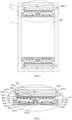
- the present embodiment of the invention provides an anesthesia ventilator device that dynamically monitors and regulates partial pressure of carbon dioxide, as shown in Figures 1-4 .
- the device comprises a ventilator main body1 with an input end connected to an oxygen source 100, an air source 101, an anesthetic gas source 102, and a carbon dioxide source 103, and an output end connected to a mask 104.
- the anesthetic gas source 102 comprises any one of nitrous oxide gas source, ether gas source, sevoflurane gas source, and desflurane gas source.
- the mask 104 When in use, the mask 104 is placed on the patient's face, and the oxygen source 100, air source 101, anesthetic gas source 102, and carbon dioxide source 103 are used to provide oxygen, air, anesthetic gas, and carbon dioxide, respectively. Oxygen, air, anesthetic gas, and carbon dioxide are mixed inside the ventilator main body 1 and delivered to the patient's body through the mask 104.
- the present invention uses a mixture of oxygen, air source, and carbon dioxide as the carrier gas for delivering anesthetic gas. This can avoid respiratory alkalosis in patients during the use of the anesthesia ventilator device. That is, when the patient eliminates excessive carbon dioxide from the body, the carbon dioxide source 103 can timely replenish the carbon dioxide in the patient's body, thereby preventing a decrease in the partial pressure of carbon dioxide in the patient's body.
- the present invention solves the technical problem in existing anesthesia ventilator devices where excessive ventilation during use can cause the patient to exhale too much carbon dioxide, leading to a decrease in the partial pressure of carbon dioxide in the body and causing respiratory alkalosis.
- the ventilator main body 1 comprises:
- the gas supply branch 2 comprises:
- air from the air source 101 flows into the main gas supply pipeline 105
- oxygen from the oxygen source 100 enters the main gas supply pipeline 105 through the second filter 1060, the second pressure sensor 1061, the first flow control valve 1062, and the second flow sensor 1063.
- Anesthetic gas from the anesthetic gas source 102 enters the main gas supply pipeline 105 through the third filter 1070, the third pressure sensor 1071, the second flow control valve 1072, and the third flow sensor 1073.
- Carbon dioxide from the carbon dioxide source 103 enters the main gas supply pipeline 105 through the fourth filter 1080, the fourth pressure sensor 1081, and the third flow control valve 1082.
- the mixed gas of air, oxygen, anesthetic gas, and carbon dioxide is delivered to the patient for anesthesia through the mask 104 via the main gas supply pipeline 105.
- the design of the carbon dioxide source 103 prevents the occurrence of excessive ventilation in the patient during the use of the anesthesia ventilator.
- the exhaled gas from the patient enters the exhalation circuit 109 through the mask 104 and is discharged to the environment 1093 through the pressure regulating diaphragm valve 1092.
- the first filter 1050, the second filter 1060, the thirdThe first filter 1050, the second filter 1060, the third filter 1070, and the fourth filter 1080 are used to filter the air from the air source 101 entering the main gas supply pipeline 105, the oxygen from the oxygen source 100 entering the first gas supply branch 106, the anesthetic gas from the anesthetic gas source 102 entering the second gas supply branch 107, and the carbon dioxide from the carbon dioxide source 103 entering the third gas supply branch 108, respectively.
- the first pressure sensor 1054, the second pressure sensor 1061, the third pressure sensor 1071, the fourth pressure sensor 1081, and the fifth pressure sensor 1091 are used to detect the pressure in the main gas supply pipeline 105, the first gas supply branch 106, the second gas supply branch 107, the third gas supply branch 108, and the exhalation circuit 109, respectively.
- the first flow sensor 1055, the second flow sensor 1063, and the third flow sensor 1073 are used to detect the flow rate of the mixed gas in the main gas supply pipeline 105, the flow rate of oxygen in the first gas supply branch 106, and the flow rate of anesthetic gas in the second gas supply branch 107, respectively.
- the first flow control valve 1062, the second flow control valve 1072, and the third flow control valve1082 are used to regulate and control the flow rate of oxygen in the first gas supply branch 106, the flow rate of anesthetic gas in the second gas supply branch 107, and the flow rate of carbon dioxide in the third gas supply branch 108, respectively.
- the first check valve 1051, the second check valve 1052, and the third check valve 1053 prevent backflow of the mixed gas in the main gas supply pipeline 105.
- the breath gas generator 1057 is used to generate the mixed input gas, also known as tidal gas, which consists of oxygen, air, and anesthetic gas.
- the heated humidifier 1056 is used to heat and humidify the tidal gas to make it suitable for patient respiration.
- the oxygen from the oxygen source 100 can flow into the environment 1093 through the fourth flow control valve 1090, the fifth pressure sensor 1091, and the throttle valve 1094.
- the fourth flow control valve 1090 By adjusting the fourth flow control valve 1090, the pressure value of the exhalation circuit 109 can be adjusted, which in turn adjusts the detection value of the fifth pressure sensor 1091.
- the detection value of the fifth pressure sensor 1091 represents the pressure value (end-expiratory positive pressure) at the pressure regulating diaphragm valve 1092.By adjusting the end-expiratory positive pressure, the respiratory tract can be maintained at a certain positive pressure during the expiration phase, avoiding early closure of the alveoli and promoting the expansion of partially non-ventilated alveoli due to exudation or lung collapse, thereby increasing the functional residual capacity and improving blood oxygenation.
- the described technical solution provides a ventilator system with multiple gas sources (air, oxygen, anesthetic gas, and carbon dioxide) that are filtered, controlled, and mixed to deliver a suitable gas mixture to the patient for anesthesia. It comprises various sensors and valves to monitor and regulate gas pressure and flow rates, ensuring the safety and effectiveness of the respiratory process. Additionally, features such as the carbon dioxide source design and the pressure regulation mechanism contribute to optimizing ventilation and maintaining positive pressure in the respiratory tract.
- gas sources air, oxygen, anesthetic gas, and carbon dioxide
- the anesthesia ventilator device further comprises:
- the exhaled impurity filtration cleaning assembly 3 comprises:
- the exhaled gas from the patient passes through two impurity filter meshes 3000 and is finally discharged into the environment 1093.
- impurities in the gas adhere to the impurity filter mesh 3000, preventing impurities from blocking the exhalation circuit 109 and ensuring the smooth operation of the anesthesia ventilator.
- the magnetic compression piston 3005 When replacing the impurity filter mesh 3000, the magnetic compression piston 3005 is manually pressed, causing the magnetic compression piston 3005 to compress the piezoelectric ceramic 3007. After the piezoelectric ceramic 3007 is compressed, the electromagnet 3020 is energized, and the two electromagnets 3020 attract and compress the second elastic element 302. At the same time, the sliding block 3009 transitions from a state of mutual cooperation with the mounting hole 3003 to a state of disengagement from the mounting hole 3003. At this point, the impurity filter mesh 3000 can be manually pulled out for replacement.
- the second driving component is used to drive the partition 3023 to slide upward and close the recovery filter assembly casing 300, preventing cleaning liquid from entering the exhalation circuit 109.
- the first driving component drives the threaded shaft 3011 to rotate.
- the rotation of the threaded shaft 3011 moves the threaded nut 3012 along the threaded shaft 3011.
- the threaded nut 3012 moves downward along the threaded shaft 3011.
- the compression airbag 3017 and the third elastic element 3018 are compressed.
- the first driving component drives the threaded shaft 3011 to reverse, causing the threaded nut 3012 to move upward along the threaded shaft 3011.
- the compression airbag 3017 gradually returns to its original length under the action of the third elastic element 3018.
- the suction tube 3024 draws water from the cleaning liquid storage tank 3021 into the compressed airbag 3017.
- the compression airbag 3017 is compressed again, and the water inside the compression airbag 3017 is pressed into the water outlet barrel 3014 and sprayed out through the water outlet hole 3015.
- the electric cleaning extensible brush 3016 is driven to move up and down, thereby cleaning the impurity filter mesh 3000.
- the cleaning intensity of the electric cleaning extensible brush 3016 can be adjusted by extending or retracting it. The cleaned impurities are collected in the impurity collection hole 3019.
- the air source 101 is equipped with a dust supplement assembly 4, which comprises:
- the negative ion emitter 407 emits negative ions into the air source 101, causing the dust in the air inside the air source 101 to carry a negative charge.
- the third driving component drives the connecting rod 4064 to rotate.
- the rotation of the connecting rod 4064 drives the electrostatic adsorption net connecting rod 4065 to flip 180 degrees from the position shown in Figure 4 .
- power is supplied to the electrostatic adsorption net 4066, and the electrostatic adsorption net 4066 adsorbs the negatively charged dust in the air source 101.
- the length of the electrostatic adsorption net 4066 can be adjusted by sliding along the guide groove 4062 with the help of the guide plate 4061.
- the electrostatic adsorption net 4066 flips back to the position shown in Figure 4 , and the second power supply component is disconnected from the strip-shaped electromagnet 405, while the first power supply component is disconnected from the coil electromagnet 401 (initially, the second power supply component supplies power to the strip-shaped electromagnet 405, and the first power supply component supplies power to the coil electromagnet 401, causing the cleaning plate 402 to be located inside the cleaning plate storage groove 4000 under the action ofthe electromagnetic force). Under the action of the reset spring 404, the cleaning plate 402 extends out of the cleaning plate storage groove 4000, and the cleaning bristles 403 on it come into contact with the electrostatic adsorption net 4066.
- the electrostatic adsorption net 4066 is powered off, and the fourth driving component drives the electrostatic adsorption net connecting rod 4065 to rotate.
- the rotation of the electrostatic adsorption net connecting rod 4065 drives the electrostatic adsorption net 4066 to rotate, causing the dust on the electrostatic adsorption net 4066 to adhere to the cleaning bristles 403.
- the electrostatic adsorption net connecting rod 4065 flips again to engage in the adsorption work.
- the fifth driving component drives the negative pressure fan 408 to rotate, and the negative pressure fan 408 sucks the dust on the cleaning bristles 403 onto the dust adsorption net 4081.
- the sprayer 4083 wets the dust adsorption net 4081, and the sliding driving component drives the dust scraping sleeve 4082 to slide along the dust adsorption net 4081, scraping the dust on the dust adsorption net 4081 into the dust collection trough 4084.
- the anesthesia ventilator device further comprises:
- the filter replacement alarm system comprises:
- the controller compares the actual clogging condition of the air filter with the preset clogging condition. If the actual clogging condition is greater than the preset condition, the alarm will be triggered.
- the greater the difference in airflow velocity on both sides of the air filter the more severe the actual clogging condition.
- the higher the dynamic viscosity of the air the more severe the actual clogging condition.
- the thicker the air filter the more severe the actual clogging condition.
- the higher the preset impurity density in the air source 101 the more severe the actual clogging condition of the air filter.
- the design of the filter replacement alarm system ensures timely replacement of the air filter, guarantees the cleanliness of the air in the oxygen source 101, and improves the safety of the anesthesia ventilator.
Landscapes
- Health & Medical Sciences (AREA)
- Anesthesiology (AREA)
- Pulmonology (AREA)
- Life Sciences & Earth Sciences (AREA)
- Engineering & Computer Science (AREA)
- General Health & Medical Sciences (AREA)
- Heart & Thoracic Surgery (AREA)
- Hematology (AREA)
- Emergency Medicine (AREA)
- Animal Behavior & Ethology (AREA)
- Biomedical Technology (AREA)
- Public Health (AREA)
- Veterinary Medicine (AREA)
- Biodiversity & Conservation Biology (AREA)
- Ecology (AREA)
- Environmental & Geological Engineering (AREA)
- Environmental Sciences (AREA)
- Respiratory Apparatuses And Protective Means (AREA)
Applications Claiming Priority (2)
| Application Number | Priority Date | Filing Date | Title |
|---|---|---|---|
| CN202210578227.9A CN114870179B (zh) | 2022-05-25 | 2022-05-25 | 一种动态监控与调控二氧化碳分压的麻醉呼吸机装置 |
| PCT/CN2023/089765 WO2023226651A1 (fr) | 2022-05-25 | 2023-04-21 | Respirateur d'anesthésie pour la surveillance et la régulation dynamiques de la pression partielle de dioxyde de carbone |
Publications (4)
| Publication Number | Publication Date |
|---|---|
| EP4316557A1 true EP4316557A1 (fr) | 2024-02-07 |
| EP4316557A4 EP4316557A4 (fr) | 2024-08-28 |
| EP4316557C0 EP4316557C0 (fr) | 2025-01-01 |
| EP4316557B1 EP4316557B1 (fr) | 2025-01-01 |
Family
ID=82678320
Family Applications (1)
| Application Number | Title | Priority Date | Filing Date |
|---|---|---|---|
| EP23792859.3A Active EP4316557B1 (fr) | 2022-05-25 | 2023-04-21 | Respirateur d'anesthésie pour la surveillance et la régulation dynamiques de la pression partielle de dioxyde de carbone |
Country Status (4)
| Country | Link |
|---|---|
| US (1) | US20250082880A1 (fr) |
| EP (1) | EP4316557B1 (fr) |
| CN (1) | CN114870179B (fr) |
| WO (1) | WO2023226651A1 (fr) |
Families Citing this family (8)
| Publication number | Priority date | Publication date | Assignee | Title |
|---|---|---|---|---|
| CN114870179B (zh) * | 2022-05-25 | 2023-04-18 | 广州蓝仕威克医疗科技有限公司 | 一种动态监控与调控二氧化碳分压的麻醉呼吸机装置 |
| CN116688300B (zh) * | 2023-07-03 | 2024-02-06 | 广州蓝仕威克医疗科技有限公司 | 一种连接通用呼吸机的co2及其它气体补偿装置及系统 |
| CN117100966B (zh) * | 2023-10-12 | 2024-05-17 | 广州蓝仕威克医疗科技有限公司 | 一种空氧及氧气和二氧化碳混合通气控制气路及呼吸装置 |
| CN117949612B (zh) * | 2024-03-26 | 2024-09-06 | 于观留 | 一种大气污染环境监测装置 |
| CN118276498B (zh) * | 2024-06-03 | 2024-07-30 | 中润华谷(南京)科技有限公司 | 一种工业控制物联设备的安全控制方法及系统 |
| CN118987858B (zh) * | 2024-10-21 | 2025-02-07 | 广东绿韶环保工程有限公司 | 一种具有降噪除尘功能的烟草生产废气异味处理设备 |
| CN119770807B (zh) * | 2024-12-27 | 2025-07-11 | 垠雨医疗科技(浙江)有限公司 | 一种二氧化碳呼吸机 |
| CN121162728B (zh) * | 2025-11-21 | 2026-03-27 | 福建科迪厨卫有限公司 | 一种伸缩式厨房水龙头及其使用方法 |
Family Cites Families (18)
| Publication number | Priority date | Publication date | Assignee | Title |
|---|---|---|---|---|
| US5320093A (en) * | 1990-12-21 | 1994-06-14 | Brigham And Women's Hospital | Rapid anesthesia emergence system using closed-loop PCO2 control |
| JPH0984876A (ja) * | 1995-09-20 | 1997-03-31 | Daido Hoxan Inc | 二酸化炭素吸入療法用ガス混合装置 |
| JP3947493B2 (ja) * | 2003-05-26 | 2007-07-18 | 日本無線株式会社 | 光コネクタの端面清掃具 |
| JP5366738B2 (ja) * | 2009-09-25 | 2013-12-11 | 株式会社アンレット | ミスト及び粉塵の捕集装置 |
| US9233218B2 (en) * | 2011-01-10 | 2016-01-12 | General Electric Comapny | System and method of controlling the delivery of medical gases to a patient |
| HUP1400421A2 (hu) * | 2014-09-10 | 2016-03-29 | Gyarmathy Agnes Dr Pomozine | Berendezés belélegzett levegõ CO2 tartalmának beállítására és/vagy szabályozására |
| GB2548548B (en) * | 2016-02-23 | 2020-12-09 | Sagetech Medical Equipment Ltd | Improvements in the capture and elution of halocarbons by supercritical fluids |
| CN105727412A (zh) * | 2016-05-04 | 2016-07-06 | 南京乐基医疗器械有限公司 | 一种麻醉机系统及其控制方法 |
| CN106139343B (zh) * | 2016-06-29 | 2018-11-23 | 广州蓝仕威克医疗科技有限公司 | 一种气体中毒急救设备 |
| CN106178210A (zh) * | 2016-08-08 | 2016-12-07 | 珠海威泓医疗科技有限公司 | 气体中毒急救呼吸机 |
| US10946160B2 (en) * | 2017-03-23 | 2021-03-16 | General Electric Company | Medical vaporizer with carrier gas characterization, measurement, and/or compensation |
| CN108731014B (zh) * | 2018-05-31 | 2019-09-13 | 重庆市永川区植成家俱厂 | 锅炉烟气除尘系统 |
| DE102021006542B3 (de) * | 2020-05-13 | 2025-06-26 | Drägerwerk AG & Co. KGaA | Gasverteilungseinheit für ein System zu Beatmung und Oxygenierung |
| CN111734659B (zh) * | 2020-06-30 | 2021-07-20 | 洲洲机电股份有限公司 | 一种纺织厂用自清洁排风机 |
| GB202013882D0 (en) * | 2020-09-03 | 2020-10-21 | Peninsula Medical Tech Ltd | Improvements in or relating to anaesthesia |
| CN113456962A (zh) * | 2021-07-26 | 2021-10-01 | 苏州鱼得水电气科技有限公司 | 一种具有加湿加热功能的呼吸机阻塞报警装置 |
| CN114366971A (zh) * | 2022-02-22 | 2022-04-19 | 驻马店市中心医院 | 一种安全性高的麻醉工作站系统 |
| CN114870179B (zh) * | 2022-05-25 | 2023-04-18 | 广州蓝仕威克医疗科技有限公司 | 一种动态监控与调控二氧化碳分压的麻醉呼吸机装置 |
-
2022
- 2022-05-25 CN CN202210578227.9A patent/CN114870179B/zh active Active
-
2023
- 2023-04-21 US US18/290,448 patent/US20250082880A1/en active Pending
- 2023-04-21 EP EP23792859.3A patent/EP4316557B1/fr active Active
- 2023-04-21 WO PCT/CN2023/089765 patent/WO2023226651A1/fr not_active Ceased
Also Published As
| Publication number | Publication date |
|---|---|
| US20250082880A1 (en) | 2025-03-13 |
| EP4316557A4 (fr) | 2024-08-28 |
| CN114870179B (zh) | 2023-04-18 |
| EP4316557C0 (fr) | 2025-01-01 |
| CN114870179A (zh) | 2022-08-09 |
| WO2023226651A1 (fr) | 2023-11-30 |
| EP4316557B1 (fr) | 2025-01-01 |
Similar Documents
| Publication | Publication Date | Title |
|---|---|---|
| EP4316557B1 (fr) | Respirateur d'anesthésie pour la surveillance et la régulation dynamiques de la pression partielle de dioxyde de carbone | |
| JP7232879B2 (ja) | 酸化窒素を生成するためのシステムおよび方法 | |
| JP6948436B2 (ja) | 酸化窒素を生成するためのシステムおよび方法 | |
| US20220162070A1 (en) | Systems and Methods for Generating Nitric Oxide | |
| JP5818214B2 (ja) | 人工呼吸器 | |
| US6196222B1 (en) | Tracheal gas insufflation delivery system for respiration equipment | |
| US8584676B2 (en) | Breath responsive filter blower respirator system | |
| EP3254632A1 (fr) | Humidification de circuits respiratoires | |
| CN117279685A (zh) | 用于生成和输送一氧化氮的系统和方法 | |
| WO1999013931A1 (fr) | Respirateur portable | |
| CN106422011A (zh) | 一种可移动自动调节呼吸机 | |
| CN113069653A (zh) | 一种新型多功能呼吸机 | |
| WO2004074746A2 (fr) | Dispositif et procede de reduction de circulation de polarisation dans des ventilateurs oscillatoires | |
| CN110464950A (zh) | 一种高频呼吸机系统及通气控制方法 | |
| DE102021000128A1 (de) | Verfahren und Vorrichtung zur Anfeuchtung von Atemgas | |
| CN210020707U (zh) | 一种便携式制氧正压通气治疗机 | |
| CN107308531A (zh) | 呼吸机及其多功能吸气阀 | |
| CN204484979U (zh) | 一种具有气体质量改善功能的呼吸机 | |
| CN110464949B (zh) | 一种高频呼吸机系统 | |
| CN222983476U (zh) | 呼吸同步超声波气道给药系统 | |
| JP2006255080A (ja) | 酸素濃縮装置 | |
| CN117899318B (zh) | 一种单水平正压通气治疗机及智能控制系统 | |
| CN222899933U (zh) | 一种呼吸机过滤装置 | |
| JP3122293U (ja) | 酸素濃縮装置 | |
| CN222488449U (zh) | 一种用于急救一体机的呼吸装置及急救一体机 |
Legal Events
| Date | Code | Title | Description |
|---|---|---|---|
| STAA | Information on the status of an ep patent application or granted ep patent |
Free format text: STATUS: UNKNOWN |
|
| STAA | Information on the status of an ep patent application or granted ep patent |
Free format text: STATUS: THE INTERNATIONAL PUBLICATION HAS BEEN MADE |
|
| PUAI | Public reference made under article 153(3) epc to a published international application that has entered the european phase |
Free format text: ORIGINAL CODE: 0009012 |
|
| STAA | Information on the status of an ep patent application or granted ep patent |
Free format text: STATUS: REQUEST FOR EXAMINATION WAS MADE |
|
| 17P | Request for examination filed |
Effective date: 20231030 |
|
| AK | Designated contracting states |
Kind code of ref document: A1 Designated state(s): AL AT BE BG CH CY CZ DE DK EE ES FI FR GB GR HR HU IE IS IT LI LT LU LV MC ME MK MT NL NO PL PT RO RS SE SI SK SM TR |
|
| A4 | Supplementary search report drawn up and despatched |
Effective date: 20240730 |
|
| RIC1 | Information provided on ipc code assigned before grant |
Ipc: B03C 3/74 20060101ALI20240724BHEP Ipc: B03C 3/04 20060101ALI20240724BHEP Ipc: A61M 16/16 20060101ALI20240724BHEP Ipc: A61M 16/10 20060101ALI20240724BHEP Ipc: A61M 16/00 20060101ALI20240724BHEP Ipc: A61M 16/01 20060101AFI20240724BHEP |
|
| GRAP | Despatch of communication of intention to grant a patent |
Free format text: ORIGINAL CODE: EPIDOSNIGR1 |
|
| STAA | Information on the status of an ep patent application or granted ep patent |
Free format text: STATUS: GRANT OF PATENT IS INTENDED |
|
| DAV | Request for validation of the european patent (deleted) | ||
| DAX | Request for extension of the european patent (deleted) | ||
| INTG | Intention to grant announced |
Effective date: 20240917 |
|
| GRAS | Grant fee paid |
Free format text: ORIGINAL CODE: EPIDOSNIGR3 |
|
| GRAA | (expected) grant |
Free format text: ORIGINAL CODE: 0009210 |
|
| STAA | Information on the status of an ep patent application or granted ep patent |
Free format text: STATUS: THE PATENT HAS BEEN GRANTED |
|
| AK | Designated contracting states |
Kind code of ref document: B1 Designated state(s): AL AT BE BG CH CY CZ DE DK EE ES FI FR GB GR HR HU IE IS IT LI LT LU LV MC ME MK MT NL NO PL PT RO RS SE SI SK SM TR |
|
| REG | Reference to a national code |
Ref country code: GB Ref legal event code: FG4D |
|
| REG | Reference to a national code |
Ref country code: DE Ref legal event code: R096 Ref document number: 602023001605 Country of ref document: DE |
|
| REG | Reference to a national code |
Ref country code: CH Ref legal event code: EP |
|
| REG | Reference to a national code |
Ref country code: IE Ref legal event code: FG4D |
|
| U01 | Request for unitary effect filed |
Effective date: 20250124 |
|
| U07 | Unitary effect registered |
Designated state(s): AT BE BG DE DK EE FI FR IT LT LU LV MT NL PT RO SE SI Effective date: 20250131 |
|
| U20 | Renewal fee for the european patent with unitary effect paid |
Year of fee payment: 3 Effective date: 20250430 |
|
| PG25 | Lapsed in a contracting state [announced via postgrant information from national office to epo] |
Ref country code: PL Free format text: LAPSE BECAUSE OF FAILURE TO SUBMIT A TRANSLATION OF THE DESCRIPTION OR TO PAY THE FEE WITHIN THE PRESCRIBED TIME-LIMIT Effective date: 20250101 |
|
| PG25 | Lapsed in a contracting state [announced via postgrant information from national office to epo] |
Ref country code: ES Free format text: LAPSE BECAUSE OF FAILURE TO SUBMIT A TRANSLATION OF THE DESCRIPTION OR TO PAY THE FEE WITHIN THE PRESCRIBED TIME-LIMIT Effective date: 20250101 |
|
| PG25 | Lapsed in a contracting state [announced via postgrant information from national office to epo] |
Ref country code: NO Free format text: LAPSE BECAUSE OF FAILURE TO SUBMIT A TRANSLATION OF THE DESCRIPTION OR TO PAY THE FEE WITHIN THE PRESCRIBED TIME-LIMIT Effective date: 20250401 Ref country code: IS Free format text: LAPSE BECAUSE OF FAILURE TO SUBMIT A TRANSLATION OF THE DESCRIPTION OR TO PAY THE FEE WITHIN THE PRESCRIBED TIME-LIMIT Effective date: 20250501 |
|
| PG25 | Lapsed in a contracting state [announced via postgrant information from national office to epo] |
Ref country code: HR Free format text: LAPSE BECAUSE OF FAILURE TO SUBMIT A TRANSLATION OF THE DESCRIPTION OR TO PAY THE FEE WITHIN THE PRESCRIBED TIME-LIMIT Effective date: 20250101 |
|
| PG25 | Lapsed in a contracting state [announced via postgrant information from national office to epo] |
Ref country code: GR Free format text: LAPSE BECAUSE OF FAILURE TO SUBMIT A TRANSLATION OF THE DESCRIPTION OR TO PAY THE FEE WITHIN THE PRESCRIBED TIME-LIMIT Effective date: 20250402 |
|
| PG25 | Lapsed in a contracting state [announced via postgrant information from national office to epo] |
Ref country code: CZ Free format text: LAPSE BECAUSE OF FAILURE TO SUBMIT A TRANSLATION OF THE DESCRIPTION OR TO PAY THE FEE WITHIN THE PRESCRIBED TIME-LIMIT Effective date: 20250101 |
|
| PG25 | Lapsed in a contracting state [announced via postgrant information from national office to epo] |
Ref country code: SM Free format text: LAPSE BECAUSE OF FAILURE TO SUBMIT A TRANSLATION OF THE DESCRIPTION OR TO PAY THE FEE WITHIN THE PRESCRIBED TIME-LIMIT Effective date: 20250101 |
|
| PG25 | Lapsed in a contracting state [announced via postgrant information from national office to epo] |
Ref country code: SK Free format text: LAPSE BECAUSE OF FAILURE TO SUBMIT A TRANSLATION OF THE DESCRIPTION OR TO PAY THE FEE WITHIN THE PRESCRIBED TIME-LIMIT Effective date: 20250101 |
|
| PLBE | No opposition filed within time limit |
Free format text: ORIGINAL CODE: 0009261 |
|
| STAA | Information on the status of an ep patent application or granted ep patent |
Free format text: STATUS: NO OPPOSITION FILED WITHIN TIME LIMIT |
|
| U1N | Appointed representative for the unitary patent procedure changed after the registration of the unitary effect |
Representative=s name: SANTARELLI; FR |
|
| 26N | No opposition filed |
Effective date: 20251002 |
|
| PG25 | Lapsed in a contracting state [announced via postgrant information from national office to epo] |
Ref country code: MC Free format text: LAPSE BECAUSE OF FAILURE TO SUBMIT A TRANSLATION OF THE DESCRIPTION OR TO PAY THE FEE WITHIN THE PRESCRIBED TIME-LIMIT Effective date: 20250101 |
|
| PG25 | Lapsed in a contracting state [announced via postgrant information from national office to epo] |
Ref country code: IE Free format text: LAPSE BECAUSE OF NON-PAYMENT OF DUE FEES Effective date: 20250421 |