EP4316760A2 - Système d'application d'un matériel de construction - Google Patents
Système d'application d'un matériel de construction Download PDFInfo
- Publication number
- EP4316760A2 EP4316760A2 EP23200998.5A EP23200998A EP4316760A2 EP 4316760 A2 EP4316760 A2 EP 4316760A2 EP 23200998 A EP23200998 A EP 23200998A EP 4316760 A2 EP4316760 A2 EP 4316760A2
- Authority
- EP
- European Patent Office
- Prior art keywords
- building material
- print head
- mixing
- binder composition
- mixing device
- Prior art date
- Legal status (The legal status is an assumption and is not a legal conclusion. Google has not performed a legal analysis and makes no representation as to the accuracy of the status listed.)
- Pending
Links
Images

Classifications
-
- B—PERFORMING OPERATIONS; TRANSPORTING
- B28—WORKING CEMENT, CLAY, OR STONE
- B28B—SHAPING CLAY OR OTHER CERAMIC COMPOSITIONS; SHAPING SLAG; SHAPING MIXTURES CONTAINING CEMENTITIOUS MATERIAL, e.g. PLASTER
- B28B1/00—Producing shaped prefabricated articles from the material
- B28B1/001—Rapid manufacturing of 3D objects by additive depositing, agglomerating or laminating of material
-
- B—PERFORMING OPERATIONS; TRANSPORTING
- B01—PHYSICAL OR CHEMICAL PROCESSES OR APPARATUS IN GENERAL
- B01F—MIXING, e.g. DISSOLVING, EMULSIFYING OR DISPERSING
- B01F25/00—Flow mixers; Mixers for falling materials, e.g. solid particles
- B01F25/40—Static mixers
- B01F25/42—Static mixers in which the mixing is affected by moving the components jointly in changing directions, e.g. in tubes provided with baffles or obstructions
- B01F25/43—Mixing tubes, e.g. wherein the material is moved in a radial or partly reversed direction
- B01F25/431—Straight mixing tubes with baffles or obstructions that do not cause substantial pressure drop; Baffles therefor
-
- B—PERFORMING OPERATIONS; TRANSPORTING
- B01—PHYSICAL OR CHEMICAL PROCESSES OR APPARATUS IN GENERAL
- B01F—MIXING, e.g. DISSOLVING, EMULSIFYING OR DISPERSING
- B01F27/00—Mixers with rotary stirring devices in fixed receptacles; Kneaders
- B01F27/05—Stirrers
- B01F27/07—Stirrers characterised by their mounting on the shaft
- B01F27/071—Fixing of the stirrer to the shaft
-
- B—PERFORMING OPERATIONS; TRANSPORTING
- B01—PHYSICAL OR CHEMICAL PROCESSES OR APPARATUS IN GENERAL
- B01F—MIXING, e.g. DISSOLVING, EMULSIFYING OR DISPERSING
- B01F27/00—Mixers with rotary stirring devices in fixed receptacles; Kneaders
- B01F27/05—Stirrers
- B01F27/07—Stirrers characterised by their mounting on the shaft
- B01F27/072—Stirrers characterised by their mounting on the shaft characterised by the disposition of the stirrers with respect to the rotating axis
- B01F27/0722—Stirrers characterised by their mounting on the shaft characterised by the disposition of the stirrers with respect to the rotating axis perpendicular with respect to the rotating axis
-
- B—PERFORMING OPERATIONS; TRANSPORTING
- B01—PHYSICAL OR CHEMICAL PROCESSES OR APPARATUS IN GENERAL
- B01F—MIXING, e.g. DISSOLVING, EMULSIFYING OR DISPERSING
- B01F27/00—Mixers with rotary stirring devices in fixed receptacles; Kneaders
- B01F27/05—Stirrers
- B01F27/11—Stirrers characterised by the configuration of the stirrers
- B01F27/112—Stirrers characterised by the configuration of the stirrers with arms, paddles, vanes or blades
- B01F27/1121—Stirrers characterised by the configuration of the stirrers with arms, paddles, vanes or blades pin-shaped
-
- B—PERFORMING OPERATIONS; TRANSPORTING
- B01—PHYSICAL OR CHEMICAL PROCESSES OR APPARATUS IN GENERAL
- B01F—MIXING, e.g. DISSOLVING, EMULSIFYING OR DISPERSING
- B01F27/00—Mixers with rotary stirring devices in fixed receptacles; Kneaders
- B01F27/21—Mixers with rotary stirring devices in fixed receptacles; Kneaders characterised by their rotating shafts
- B01F27/2123—Shafts with both stirring means and feeding or discharging means
-
- B—PERFORMING OPERATIONS; TRANSPORTING
- B28—WORKING CEMENT, CLAY, OR STONE
- B28C—PREPARING CLAY; PRODUCING MIXTURES CONTAINING CLAY OR CEMENTITIOUS MATERIAL, e.g. PLASTER
- B28C5/00—Apparatus or methods for producing mixtures of cement with other substances, e.g. slurries, mortars, porous or fibrous compositions
- B28C5/08—Apparatus or methods for producing mixtures of cement with other substances, e.g. slurries, mortars, porous or fibrous compositions using driven mechanical means affecting the mixing
- B28C5/10—Mixing in containers not actuated to effect the mixing
- B28C5/12—Mixing in containers not actuated to effect the mixing with stirrers sweeping through the materials, e.g. with incorporated feeding or discharging means or with oscillating stirrers
- B28C5/1238—Mixing in containers not actuated to effect the mixing with stirrers sweeping through the materials, e.g. with incorporated feeding or discharging means or with oscillating stirrers for materials flowing continuously through the mixing device and with incorporated feeding or discharging devices
- B28C5/1292—Mixing in containers not actuated to effect the mixing with stirrers sweeping through the materials, e.g. with incorporated feeding or discharging means or with oscillating stirrers for materials flowing continuously through the mixing device and with incorporated feeding or discharging devices with rotating stirring and feeding or discharging means fixed on the same axis, e.g. in an inclined container fed at its lower part
-
- B—PERFORMING OPERATIONS; TRANSPORTING
- B28—WORKING CEMENT, CLAY, OR STONE
- B28C—PREPARING CLAY; PRODUCING MIXTURES CONTAINING CLAY OR CEMENTITIOUS MATERIAL, e.g. PLASTER
- B28C7/00—Controlling the operation of apparatus for producing mixtures of clay or cement with other substances; Supplying or proportioning the ingredients for mixing clay or cement with other substances; Discharging the mixture
- B28C7/02—Controlling the operation of the mixing
- B28C7/022—Controlling the operation of the mixing by measuring the consistency or composition of the mixture, e.g. with supply of a missing component
- B28C7/024—Controlling the operation of the mixing by measuring the consistency or composition of the mixture, e.g. with supply of a missing component by measuring properties of the mixture, e.g. moisture, electrical resistivity, density
-
- B—PERFORMING OPERATIONS; TRANSPORTING
- B33—ADDITIVE MANUFACTURING TECHNOLOGY
- B33Y—ADDITIVE MANUFACTURING, i.e. MANUFACTURING OF THREE-DIMENSIONAL [3D] OBJECTS BY ADDITIVE DEPOSITION, ADDITIVE AGGLOMERATION OR ADDITIVE LAYERING, e.g. BY 3D PRINTING, STEREOLITHOGRAPHY OR SELECTIVE LASER SINTERING
- B33Y30/00—Apparatus for additive manufacturing; Details thereof or accessories therefor
-
- E—FIXED CONSTRUCTIONS
- E04—BUILDING
- E04G—SCAFFOLDING; FORMS; SHUTTERING; BUILDING IMPLEMENTS OR AIDS, OR THEIR USE; HANDLING BUILDING MATERIALS ON THE SITE; REPAIRING, BREAKING-UP OR OTHER WORK ON EXISTING BUILDINGS
- E04G21/00—Preparing, conveying, or working-up building materials or building elements in situ; Other devices or measures for constructional work
- E04G21/02—Conveying or working-up concrete or similar masses able to be heaped or cast
- E04G21/04—Devices for both conveying and distributing
- E04G21/0418—Devices for both conveying and distributing with distribution hose
-
- B—PERFORMING OPERATIONS; TRANSPORTING
- B33—ADDITIVE MANUFACTURING TECHNOLOGY
- B33Y—ADDITIVE MANUFACTURING, i.e. MANUFACTURING OF THREE-DIMENSIONAL [3D] OBJECTS BY ADDITIVE DEPOSITION, ADDITIVE AGGLOMERATION OR ADDITIVE LAYERING, e.g. BY 3D PRINTING, STEREOLITHOGRAPHY OR SELECTIVE LASER SINTERING
- B33Y10/00—Processes of additive manufacturing
Definitions
- the invention relates to a system for applying a building material and the use of the system for producing three-dimensional objects from curable building materials, in particular from mineral binders or mineral binder compositions, in particular from concrete and/or mortar compositions.
- generative manufacturing process refers to processes in which a spatial object or a shaped body is produced through targeted spatial deposition, application and/or solidification of material.
- the deposition, application and/or solidification of the material takes place in particular on the basis of a data model of the object to be created and in particular in layers or layers.
- Each object is typically made from one or more layers using generative manufacturing processes.
- a shapeless material e.g. liquids, powders, granules, etc.
- a shape-neutral material e.g. strips, wires
- Generative manufacturing processes are also referred to as “additive manufacturing processes”, “additive manufacturing” or “3D printing”, among other things.
- WO 2013/064826 A1 a method and a device for applying cementitious materials.
- Liquid cementitious material is applied to a destination using a movable robot arm.
- the disadvantage of such systems is that the building material is often not sufficiently constant with regard to various Properties, especially regarding mixing of components. This can lead to irregularities in a structure made with the building material.
- the cured building material composition depending on the objects to be manufactured, different requirements are placed on the cured building material composition. For example, it may be necessary to control the flow properties, kinetics and shrinkage behavior during the solidification and curing process or the strength and surface finish after curing in order to produce an object with the desired properties.
- the object of the present invention is therefore to create improved systems for the generative production of moldings.
- the systems should in particular enable efficient, reliable and as flexible as possible production of moldings from curable building materials, in particular from mineral binder compositions. If possible, this should be done with as little outlay on equipment as possible and as cost-effectively as possible.
- Binder compositions are produced. Due to the limited expenditure on equipment, the costs for the systems according to the invention can be kept relatively low.
- the system can also be expanded in a relatively simple manner for various applications using designed control units and/or optional measuring units.
- building material is understood to mean a material which is formed from or consists of at least two separate components.
- the building material is used in particular to construct three-dimensional objects, which can, for example, be components of structures and/or buildings.
- a “hardenable building material” refers to a building material that is typically flowable or liquefiable and can harden as a solid after mixing, for example by adding mixing water and/or by mixing components.
- these are reactive resins, a mineral Binders, mineral binder compositions or mixtures thereof.
- a “setting building material” is a hardenable building material in a setting or hardening state, in which the setting process has been initiated, for example by adding mixing water and/or a hardener.
- Reactive resins are in particular liquid or liquefiable synthetic resins that harden to duromers through polymerization or polyaddition.
- unsaturated polyester resins vinyl ester resins, acrylic resins, epoxy resins, polyurethane resins and/or silicone resins can be used.
- mineral binder is understood to mean, in particular, a binder which reacts in the presence of water in a hydration reaction to form solid hydrates or hydrate phases.
- This can be, for example, a hydraulic binder (e.g. cement or hydraulic lime), a latent hydraulic binder (e.g. slag), a pozzolanic binder (e.g. fly ash) or a non-hydraulic binder (e.g. gypsum or white lime).
- a “mineral binder composition” is accordingly a composition containing at least one mineral binder. In the present case, this contains in particular the binder, aggregates and optionally one or more additives. Aggregates that can be present include, for example, aggregates, gravel, sand (in natural and/or processed (e.g. broken) form) and/or fillers.
- the mixing device is designed in particular in such a way that it can be operated continuously while the setting building material is being applied.
- the mixing device is preferably designed such that an average residence time of the components of the curable building material in the mixing device, in particular a dynamic mixer, is less than 10 s, more preferably less than 7 s, particularly preferably less than 4 s.
- the average residence time of the components of the curable building material in the mixing device is the average length of time that a particle of the curable building material stays in the mixing device, from the inlet to the outlet.
- the mixing device preferably includes a dynamic mixer.
- a “dynamic mixer” is understood to mean a mixing device which comprises movable elements and is suitable for mixing solid and/or liquid components by moving the movable elements. Using a dynamic mixer, particularly effective mixing of the components can be achieved and energy can be introduced into the curable building material during the mixing process. This is particularly advantageous if the curable building material comprises a mineral binder composition.
- a static mixer can also be used.
- a static mixer is a mixer in which mixing is effected solely by the flow movement of the fluids moved through the mixer, without any moving elements being present.
- a static mixer has flow-influencing elements in a tubular mixing chamber. The flow-influencing elements can deflect, divide and/or merge the material flow, thereby achieving mixing.
- the print head is advantageously arranged spatially separated and/or spaced apart from the mixing device, in particular a dynamic mixer. This applies in particular to all dynamic mixers in the system.
- the mixing device in particular a dynamic mixer, is arranged such that when the print head moves during operation, a position of the print head is changed relative to the mixing device, in particular a dynamic mixer. This applies in particular to all dynamic mixers.
- the mixing device in particular a dynamic mixer of the mixing device, is preferably arranged stationary. This means that it does not have to move with the moving print head during operation. All dynamic mixers are preferably arranged stationary.
- the mixing device in particular a dynamic mixer, is not arranged on the movable print head and/or no mixing device, in particular no dynamic mixer, is arranged on the movable print head.
- the mixing device includes a dynamic mixer and a static mixer, the static mixer preferably being arranged in the delivery line and/or in the print head.
- the dynamic mixer is preferably arranged at a distance from the static mixer in the direction of flow.
- the dynamic mixer is arranged in front of the static mixer in the direction of flow.
- the hardenable building material can be mixed again in the static mixer after initial mixing in the dynamic mixer. If the static mixer is arranged directly in front of the print head or in the print head itself, this can be done immediately before the setting building material exits the print head, which can improve the homogeneity of the setting building material emerging from the print head.
- a static mixer in the area of the print head also has the advantage that it can be integrated into the delivery line or be present as part of it, whereby the area of the print head can be kept compact.
- static mixers are typically relatively light compared to dynamic mixers, which means that the mechanics for moving the print head have to be less robust, which reduces both the equipment complexity and the costs.
- the device for influencing the chemical and/or physical properties of the setting building material there is also a device for influencing the chemical and/or physical properties of the setting building material.
- the device for influencing the chemical and/or physical properties is preferably arranged in or on the delivery line and/or the print head. Especially in or on the print head.
- setting building material can be controlled and/or adjusted, for example with regard to the flow properties and/or the solidification behavior.
- an inlet nozzle for adding an additive to the setting building material.
- the additive serves in particular to influence the chemical and/or physical properties of the setting building material.
- the additive is preferably selected from a retarder, a rheology aid and/or a flow agent. This is preferably a retarder, a rheology aid or a flow agent for mineral binder compositions.
- Retarders are, for example, selected from the list comprising hydroxycarboxylic acids, sucrose and/or phosphates. This is particularly true if the curable building material is a mineral binder or a mineral binder composition.
- rheological aid is understood to mean a substance that can change the rheological properties of the setting building material, in particular a water-containing mineral binder composition, in particular it increases the viscosity, the yield point and/or the thixotropy.
- the rheology aid is selected from the group consisting of modified starches, modified celluloses, microbial polysaccharides and/or mineral thickeners.
- the modified starch is preferably a starch ether, in particular hydroxypropyl starch, carboxymethyl starch or carboxymethylhydroxypropyl starch.
- the modified cellulose is preferably methyl cellulose, Ethylcellulose, hydroxymethylcellulose, hydroxyethylcellulose or methylhydroxyethylcellulose.
- the above-mentioned representatives of additives can be used to adjust the flow, setting or hardening behavior of curable building materials in the form of mineral binder compositions particularly well.
- the rheology aid is particularly suitable for ensuring the dimensional stability of the water-containing binder composition and for giving an applied layer sufficient stability to support one or more further layers without significantly changing the shape.
- the use of retarders can be advantageous because it extends the processing time of the water-containing binder composition.
- the inlet nozzle is located in the flow direction in front of any static mixer and/or in the area of an outlet opening of the print head. This means that the additive can be effectively added to the setting building material and mixed with it if necessary.
- an additive can also be present as part of a component and/or as a separate component when mixing the at least two components.
- a device for ventilation and/or ventilation of the setting building material This is in particular an air supply system, a vacuum treatment device and/or a vibration device.
- the device for ventilation and/or venting is preferably present on or in the delivery line and/or on or in the print head.
- the flow properties of the setting building material can be controlled and/or changed during application using a device for ventilation and/or venting. This can be useful, for example, to keep the flow properties constant under changing environmental conditions and/or to adapt the flow properties to the section of the object to be created.
- a device for changing the temperature of the setting building material This is in particular a heating element and/or a cooling element.
- the device for changing the temperature is preferably present on or in the delivery line and/or on or in the print head.
- the temperature of the setting building material can be controlled and/or changed during application. This can be useful, for example, to monitor and/or control the solidification and/or hardening processes.
- the temperature of the setting building material can be adjusted as environmental conditions change.
- the solidification and/or hardening processes can be changed for different sections of the object to be produced by adjusting the temperature.
- the feed device is advantageously designed in such a way that a solid component of the building material can be added to the mixing device via a first inlet and a liquid component via a second inlet.
- a solid component of a mineral binder composition which comprises, for example, a mineral binder and aggregates in solid form, to be added to the mixing device via the first inlet, while a liquid component, e.g. water, is added separately from the first component via the second inlet can be.
- a liquid component e.g. water
- the feed device is designed such that at least three separate components of the building material can be added to the mixing device via at least three separate inlets.
- a solid component of a mineral binder composition comprising, for example, a mineral binder and aggregates in solid form, may be added to the mixing device via the first inlet.
- a second component which comprises, for example, fibers, can then be added separately into the mixing device via the second inlet, while the third component, for example water, can be added into the mixing device separately from the other two components via the third inlet. This means that the mixing ratio of all three components can be adjusted at any time.
- curable building material can be adapted to almost any desired composition in terms of its composition.
- the feed device advantageously has a further inlet, which corresponds, for example, to an additive reservoir, and a further outlet, which is connected to the inlet nozzle.
- fibers are understood to mean materials whose ratio of length to diameter or length to equivalent diameter is at least 10:1. This ratio is also known as the form factor.
- equivalent diameter of a fiber is understood to mean the diameter of a circle having the same area as the cross-sectional area of a fiber with a non-round cross-section.
- the feeding device has in particular at least one or more metering devices.
- the at least one metering device is designed such that one or more of the components of the curable building material can be metered into the mixing device in a controlled manner and/or at a defined addition rate.
- each inlet of the mixing device prefferably has a separate and individually controllable metering device.
- the feed device advantageously has a further metering device, which is designed such that an additive can be added to the inlet nozzle in a controlled manner and/or at a defined addition rate.
- the metering device is a gravimetric metering device.
- such metering devices have proven to be easy to handle, but still precise.
- Providing a gravimetric metering device offers the advantage that a component, in particular a solid component, can be supplied to the system in precise quantities. This allows the quality of the building material to be kept constant.
- the metering device comprises a funnel and a conveyor device.
- the conveyor device can in particular be designed as a screw conveyor or conveyor belt.
- Providing a funnel and a conveyor device has the advantage that large units of a component of the building material, such as large containers or sacks (called “big bags” in technical language), can be used. For example, such large units can be hung in a container and fed to a conveyor device via a funnel.
- the funnel has the advantage that it can be used as a storage device, thus saving a period of time when the containers in the first one are replaced Part of the first component of the building material can bridge. For example, a first component can be fed to the metering device by the conveying device.
- the conveying device is present in the mixing device, in the conveying line and/or in the print head, or the conveying device is a component of these elements. This makes a compact design possible. However, arrangements of the conveyor device are also possible.
- a pump is used as the conveying device, for example a screw conveyor.
- the mixing device comprises a stirring shaft, which is equipped with stirring elements on a first section and on which a conveying element is arranged on a second section.
- the components of the curable building material can be mixed in this way in the mixing device and at the same time conveyed out of the mixing device in mixed form.
- the stirring elements are designed as pins.
- the stirring elements have an external thread, so that the stirring elements can be screwed into recesses with internal threads on the stirring shaft.
- the conveying element is designed as a screw conveyor.
- the first section of the agitator shaft is arranged in a first region of a drum of the mixer, in which the drum has at least two has inlets.
- the second section of the agitator shaft is arranged in a second area of the drum, in which the drum has an outlet.
- the conveying element can be removed from the agitator shaft in the direction of an axis of the agitator shaft.
- the conveying element comprises a fastening element for locking the conveying element on the agitator shaft.
- a drum of the mixer is designed in one piece and/or tubular.
- the system according to the invention has at least one container in which at least one of the two components of the building material can be stored.
- the system according to the invention particularly preferably has at least two containers in which the at least two components of the building material can be stored spatially separated.
- system according to the invention can have a reservoir for an additive.
- An additive which is added via the inlet nozzle, for example, can be stored in such a reservoir.
- the one or more containers preferably correspond to the feed device, so that a component present in a container can be fed directly into the mixing device via an assigned inlet.
- the system according to the invention can produce a defined part or the entire object to be produced essentially without further intervention after loading the containers and/or connecting to a transport line.
- a measuring unit with which a chemical and/or physical property of the curable building material can be determined in the mixing device, in the delivery line, in the print head and/or after delivery from the print head.
- a chemical and/or physical property of the setting building material By determining a chemical and/or physical property of the setting building material, its specific condition can be assessed. This makes it possible, if necessary, to adjust, for example, the ratio of the components, the conveying speed of the setting building material and/or the addition rate of an additive depending on the chemical and/or physical properties. Overall, a more constant quality of the curable building material can be achieved and/or the curable building material can be specifically adapted or changed for specific sections of the object to be produced.
- the measuring unit is in particular designed such that a measuring frequency for determining the chemical and/or physical property is >0.01 Hz, preferably >0.1 Hz, particularly preferably >1 Hz, very particularly preferably >10 Hz. This allows the chemical and/or physical properties of the setting building material to be determined at regular intervals or continuously.
- the measuring unit is particularly preferably designed in such a way that the chemical and/or physical property can be determined during the application of the building material, in particular in real time.
- the measuring unit is preferably arranged in the mixing device, in the delivery line and/or in the print head.
- the measuring device comprises a temperature measuring device, a pressure measuring device, a moisture measuring device, a measuring device for determining electrical conductivity, a penetrometer, an ultrasonic transducer and/or a rheometer.
- a temperature measuring device e.g., a thermometer, a pressure measuring device, a moisture measuring device, a measuring device for determining electrical conductivity, a penetrometer, an ultrasonic transducer and/or a rheometer.
- an outlet on the print head that can be controlled with respect to the size of the passage opening, the outlet preferably being completely closable.
- This can be done, for example, by means of a valve that can be opened and closed, the valve being able to be opened and closed in particular pneumatically and/or electromechanically. This allows the delivery rate to be specifically adjusted when applying the setting building material.
- the system according to the invention has a control unit.
- the control unit is designed in particular in such a way that at least some of the devices and units present in the system can be controlled and/or regulated in a controlled manner.
- the term “regulate” or “regulated” is understood in particular to mean the setting of a predetermined target value and its maintenance for a defined period of time.
- the control unit has in particular a processor, a data memory, an interface for receiving data from any existing measuring devices and/or an interface for controlling devices of the system according to the invention.
- the devices and units present in the system are preferably connected to the control unit via data lines, control lines and/or wireless communication systems.
- controllable devices are in particular the movable print head, the controllable outlet opening, the mixing device, the conveying device, the inlet nozzle and/or the feed device.
- a data model which represents at least part of the object to be created or the entire object to be created is preferably stored in the control unit.
- the control unit is also advantageously designed in such a way that parameters and/or target values to be maintained during the application can be determined taking the data model into account.
- parameters and/or target values are preferably defined for different sections of the object to be created and/or these are present in the control unit.
- the parameters or target values are, for example, the delivery rate of the conveying device, the size of the opening of the outlet nozzle, the mixing ratio of the at least two components, the addition rate of the additive via the inlet nozzle, the pressure of the setting building material, the viscosity of the setting building material, etc Temperature of the setting building material and/or the ambient temperature of the area in which the object to be created is created.
- one or more properties of the at least two components of the curable building material for example the chemical composition, a previously determined flow limit and/or a previously determined viscosity, can or are stored in the control unit.
- the control unit is preferably designed such that the size of the passage opening of the controllable outlet is controlled depending on the structure of the object to be produced. This allows the structure to be created to be produced more precisely and in a more controlled manner.
- control unit is designed in such a way that the conveying capacity of the conveying device is determined in relation to a chemical and/or physical property of the curable building material determined by the measuring unit, in particular in relation to a pressure of the curable building material in the conveying line and/or in the print head. is controlled and/or regulated.
- control unit is designed such that the conveying capacity of the conveying device is regulated in relation to a fill level of the components in one or more containers. This can prevent the system from running empty and air being introduced.
- control is designed in such a way that an addition rate of at least one component of the building material with the feed device depends on the chemical and/or physical properties of the curable building material and/or depending on the size and/or structure of the material to be created Object, can be regulated or takes place.
- the composition and properties of the curable building material can be kept constant and/or adjusted in a targeted manner.
- the control is advantageously designed in such a way that the addition rate can or does take place during the application of the curable building material, in particular in real time.
- control unit which is designed such that a volume flow of the curable building material emerging from the print head depends on the size and/or the structure of an object to be created with the curable building material.
- the control unit is preferably designed in such a way that the conveying device takes place depending on a chemical and/or physical property of the curable building material and/or depending on the size and/or structure of an object to be produced with the curable building material.
- control unit is designed in particular in such a way that an addition rate of an additive, in particular a rheology aid and/or a retarder, via the inlet nozzle depends on a chemical and/or physical property of the curable building material and/or depending on the size and/or the Structure of an object to be created with the curable building material is controlled.
- control unit is designed in such a way that the application of the setting building material is controlled and/or regulated taking into account the ambient temperature of an area in which the object to be created is created.
- the addition rate of an additive via the inlet nozzle, the delivery rate of the conveying device and/or the addition rate of at least one component of the building material can be controlled and/or regulated depending on the ambient temperature of an area in which the object to be created is produced.
- control unit is designed such that the delivery rate and the movement of the print head are coordinated with one another.
- the first component is a dry mineral binder composition comprising cement and mineral fillers, the binder composition containing at least one setting accelerator based on aluminum sulfate, at least one superplasticizer based on a polycarboxylate ether and comprises at least one rheology aid, wherein the polycarboxylate ether, assuming all carboxylic acid groups are present as a free acid, has at least 1 mmol, in particular at least 1.2 mmol, in particular at least 1.8 mmol, of carboxylic acid groups per gram of dry polycarboxylate ether.
- dry mineral binder composition is understood to mean a free-flowing mineral binder composition with a moisture content of less than 0.5% by weight.
- water-containing mineral binder composition is understood to mean a mineral binder composition mixed with water, in particular in fluid form. Accordingly, a “water-containing mineral binder composition” is a curable building material in a setting state.
- polycarboxylate ether is understood to mean a comb polymer comprising a backbone made of hydrocarbons with carboxylic acid groups or their salts bound thereto and polyalkylene glycol side chains also covalently bound to the backbone.
- the side chains are bonded to the polycarboxylate backbone in particular via ester, ether, imide and/or amide groups.
- the amount of carboxylic acid groups in the polycarboxylate ether is understood to be millimoles of carboxylic acid groups in one gram of the polycarboxylate ether (mmol/g).
- any salts of the carboxylic acids that may be present are counted among the carboxylic acid groups and the weight of the polycarboxylate ether is used in non-neutralized form.
- Carboxylic acid esters are not counted among the carboxylic acid groups here, even if they are present in latent form, that is, if they can be hydrolyzed in an alkaline medium at pH 12.
- dimensional stability is understood to mean a material property in which the material changes the individual dimensions by a maximum of 10% after shaping, provided that no external force other than gravity acts on the shaped material.
- “stability” is understood to mean the strength that a curable material has after application before curing.
- cement type or a mixture of two or more cement types can be used as cement, for example those classified under DIN EN 197-1 Cements: Portland cement (CEM I), Portland composite cement (CEM II), blast furnace slag cement (CEM III), Pozzolanic cement (CEM IV) and composite cement (CEM V).
- CEM I Portland cement
- CEM II Portland composite cement
- CEM III blast furnace slag cement
- CEM IV Pozzolanic cement
- CEM V composite cement
- cements produced according to an alternative standard such as the ASTM standard or the Indian standard, are equally suitable.
- Portland cement CEM I or CEM II according to DIN EN 197-1 is preferred.
- Portland cement CEM 142.5 or CEM I 52.5 is particularly preferred. Such cements provide good strength and good workability.
- the dry mineral binder composition advantageously also contains at least one latent hydraulic or pozzolanic binder, in particular metakaolin and/or silica fume (amorphous SiO 2 ).
- the latent hydraulic or pozzolanic binder is preferably present in the binder composition in 0.1 to 10% by weight, in particular in 0.5 to 5% by weight. These additives can increase the processability of the aqueous binder composition and the strength of the cured binder composition.
- the dry mineral binder composition contains mineral fillers.
- Fillers are chemically inert solid particulate materials and are offered in various shapes, sizes and materials, ranging from the finest sand particles to large coarse stones. In principle, all fillers that are commonly used for concrete and mortar are suitable. Examples of particularly suitable fillers are aggregates, gravel, sand, especially quartz sand, limestone sand and slag sand, crushed stones, calcined pebbles or light fillers such as expanded clay, expanded glass, foam glass, pumice, perlite and vermiculite. Further advantageous fillers are fine or very fine fillers such as ground limestone or dolomite, aluminum oxide, silica fume, quartz powder or ground steel slag with no or only weak latent hydraulic reactivity.
- Preferred fillers are selected from the group consisting of quartz sand, quartz powder, limestone sand, ground limestone and ground steel slag.
- the filler preferably comprises at least one finely ground crystalline filler, in particular limestone. This can promote the early strength development of the binder composition mixed with water.
- the particle size of the fillers depends on the application and ranges from 0.1 ⁇ m to 32 mm and more. Different particle sizes are preferably mixed in order to optimally adjust the properties of the binder composition. Fillers made from different materials can also be mixed. The particle size can be determined using a sieve analysis.
- the particle size is determined in particular by the planned layer thickness of the applied layers in 3D printing or the generative manufacturing process. A maximum particle size of the fillers is therefore sensibly as large as the layer thickness during application.
- the dry mineral binder composition preferably contains 20 to 40% by weight, in particular 22 to 36% by weight, based on the total weight of the dry binder composition, of fine fillers with a particle size of less than 0.125 mm.
- Suitable fillers with a small particle size are, in particular, fine quartz sand, quartz powder, ground calcium carbonate or ground steel slag.
- the mineral binder composition preferably contains 1 to 10% by weight, more preferably 2 to 5% by weight, of ground calcium carbonate with a particle size of less than 0.01 mm.
- the fine calcium carbonate improves the processability of the water-mixed binder composition and can increase the strength development of the binder composition.
- Aqueous binder compositions with such particle sizes are easy to convey, can be mixed well with the aqueous accelerator in the continuous mixer and result in a very homogeneous surface after application.
- fillers with particle sizes of up to 32 mm, more preferably up to 20 mm, most preferably up to 16 mm, can also be used.
- the mineral fillers are preferably present in 45 to 85% by weight, in particular 50 to 80% by weight, based on the total weight of the dry mineral binder composition.
- the dry mineral binder composition preferably contains an aluminum sulfate-based accelerator.
- the accelerator is a free-flowing powder and advantageously contains at least 30% by weight, preferably at least 35% by weight, more preferably at least 40% by weight, aluminum sulfate, calculated as aluminum sulfate hydrate Al 2 (SO 4 ) 3 ⁇ 16 H 2 O.
- the accelerator can advantageously contain other components such as amino alcohols, alkali and alkaline earth metal nitrates, alkali and alkaline earth metal nitrites, alkali and alkaline earth metal thiocyanates, alkali and alkaline earth metal halides, alkali carbonates, glycerol, glycerol derivatives, other aluminum salts, aluminum hydroxides, alkali and alkaline earth metal hydroxides, alkali - and alkaline earth metal silicates, alkali and alkaline earth metal oxides or alkali and alkaline earth metal salts of formic acid, or mixtures thereof.
- other components such as amino alcohols, alkali and alkaline earth metal nitrates, alkali and alkaline earth metal nitrites, alkali and alkaline earth metal thiocyanates, alkali and alkaline earth metal halides, alkali carbonates, glycerol, glycerol derivatives, other aluminum salt
- the accelerator consists of at least 90% by weight, in particular at least 95% by weight, of aluminum sulfate hydrate or is aluminum sulfate hydrate.
- the binder composition is preferably free of amino alcohols.
- Amino alcohols have an intense, unpleasant smell, can endanger health and lead to uncontrolled stiffening of the binder composition mixed with water.
- the accelerator based on aluminum sulfate is preferably present in 0.1 to 2% by weight, more preferably in 0.3 to 1.5% by weight, in particular in 0.4 to 1.0% by weight, based on the total weight of the dry mortar mixture.
- Such a dosage of the accelerator leads to a rapid development of strength of the binder composition mixed with water without restricting the processability for the printing process, especially in combination with polycarboxylate ethers.
- the binder composition comprises at least one superplasticizer based on a polycarboxylate ether.
- the at least one polycarboxylate ether contains carboxylic acid groups in the form of free, that is to say non-neutralized, carboxylic acid groups and/or in the form of their alkali metal and/or alkaline earth metal salts. Polycarboxylate ethers which have no further anionic groups in addition to the carboxylic acid groups are preferred.
- polycarboxylate ethers whose side chains consist of at least 80 mol%, preferably at least 90 mol%, particularly preferably 100 mol%, of ethylene glycol units.
- the side chains preferably have an average molecular weight Mw in the range from 500 to 10,000 g/mol, preferably 800 to 8,000 g/mol, particularly preferably 1,000 to 5,000 g/mol. It Side chains with different molecular weights may also be present in the polycarboxylate ether.
- polycarboxylate ethers which are made up of methacrylic acid and/or acrylic acid units and methyl polyalkylene glycol methacrylates or acrylates.
- the at least one polycarboxylate ether preferably has an average molecular weight Mw of 8,000 to 200,000 g/mol, in particular 10,000 to 100,000 g/mol, measured against polyethylene glycol standards.
- Such polycarboxylate ethers are particularly suitable for enabling good processability of the binder composition even at low water contents.
- a low water content results in high strength of a hardened molded body.
- such polycarboxylate ethers work particularly well as an agent for controlling the stiffening of the aqueous binder composition.
- the at least one polycarboxylate ether can be introduced into the binder composition as an aqueous solution, for example by spraying onto the fillers before mixing with the mineral binder.
- the at least one polycarboxylate ether is preferably present as a polymer powder in the dry binder composition.
- the at least one polycarboxylate ether has a block or gradient structure.
- “polycarboxylate ether with block or gradient structure” is understood to mean a polymer in which the monomer units are present in a non-random sequence, i.e. the sequence is not obtained randomly.
- at least one section comprises monomer units comprising polyalkylene glycol side chains and no or hardly any monomer units with carboxylate groups and at least one section comprises monomer units with carboxylate groups and no or hardly any monomer units with polyalkylene glycol side chains.
- Such block or gradient polymers therefore have sections with a high density of anionic groups and sections that contain no or only a few anionic groups.
- polycarboxylate ethers with a block or gradient structure very quickly develop their effect as plasticizers. They are therefore particularly suitable for applications in which the mixing time of binder composition and water is very short, especially for continuous mixing.
- Polycarboxylate ethers with a block or gradient structure also result in a low viscosity of the binder composition, which improves pumpability.
- the liquefying effect of the polycarboxylate ethers with block or gradient structure in the binder compositions according to the invention only lasts for a few minutes, which is advantageous for 3D printing because it ensures good processability of the aqueous binder composition directly after mixing and good stability after application can be achieved.
- the at least one polycarboxylate ether is preferably present at 0.02 to 5% by weight, preferably at 0.05 to 4% by weight, in particular at 0.1 to 3% by weight, calculated as a dry polymer, based on the total weight of the dry binder composition.
- the dosage of the at least one polycarboxylate ether in the binder composition is advantageously adapted to the respective printing task.
- the printing parameters such as typically the desired height of the molded body, the thickness of the applied layers, the printing speed and the expected ambient temperature, are advantageously recorded before printing and then the optimal amount of polycarboxylate ether in the binder composition is determined using empirical values, tables and/or a computer program determined.
- the total amount of polycarboxylate ether is provided in the dry binder composition.
- the further part of the polycarboxylate ether is advantageously added together with the mixing water in a continuous mixing process.
- the binder composition can thus be produced in large quantities, which is advantageous, and the adaptation to the respective pressure conditions is carried out easily and inexpensively on the construction site.
- the binder composition preferably contains at least one organic and/or inorganic rheology aid.
- Suitable rheology aids are, in particular, modified starch, amylopectin, modified cellulose, microbial polysaccharides, galactomannans, alginates, tragacanth, polydextrose, superabsorbents or mineral thickeners.
- the rheology aid is preferably selected from the group consisting of modified starches, modified celluloses, microbial polysaccharides, superabsorbers and mineral thickeners.
- the total amount of rheology aid is preferably 0.01 to 5% by weight, based on the total weight of the dry binder composition.
- the modified starch is preferably a starch ether, in particular hydroxypropyl starch, carboxymethyl starch or carboxymethylhydroxypropyl starch.
- the modified starch is preferably present in 0.01 to 2% by weight, based on the total weight of the dry binder composition.
- the modified cellulose is preferably methylcellulose, ethylcellulose, hydroxymethylcellulose, hydroxyethylcellulose or methylhydroxyethylcellulose and is preferably present in 0.01 to 2% by weight, based on the total weight of the dry binder composition.
- the microbial polysaccharide is preferably Welan Gum, Xanthan Gum or Diutan Gum and is preferably present in 0.01 to 0.1% by weight, based on the total weight of the dry binder composition.
- the superabsorber is preferably selected from the group comprising polyacrylamide, polyacrylonitrile, polyvinyl alcohol, isobutylene-maleic anhydride copolymers, polyvinylpyrrolidone, homo- and copolymers of monoethylenically unsaturated carboxylic acids such as (meth) acrylic acid, crotonic acid, sorbic acid, maleic acid, fumaric acid, itaconic acid, preferably polyacrylic acid, which can be partially or completely neutralized, and co- and terpolymers of the above-mentioned monoethylenically unsaturated carboxylic acids with vinyl sulfonic acid, (meth) acrylamidoalkyl sulfonic acids, allyl sulfonic acid, vinyl toluene sulfonic acid, Vinylphosphonic acid, (meth)acrylamide, N-alkylated (meth)acrylamide, N-methylol (meth)acrylamide, N-vinylform
- the superabsorbent homo- and copolymers can be linear or branched; the copolymers can be present randomly or as block or gradient polymers.
- the homo- and copolymers are preferably also cross-linked.
- the superabsorber is preferably polyacrylic acid, which can be partially or completely neutralized and crosslinked.
- the superabsorbent if present, is preferably present in 0.01 to 0.5% by weight, in particular in 0.05 to 0.3% by weight, based on the total weight of the dry binder composition.
- mineral thickeners For example, special silicates or clay minerals can be used as mineral thickeners. Bentonite and sepiolite are preferred.
- the mineral thickener is preferably present in 0.1 to 1% by weight, based on the total weight of the dry binder composition.
- the binder composition preferably contains at least two, more preferably at least three, different rheology aids.
- the rheology aid is particularly suitable for ensuring the dimensional stability of the water-containing binder composition and for giving an applied layer sufficient stability to support one or more further layers without significantly changing the shape before the cement begins to hydrate.
- the different thickening properties of the rheology aids can be optimally coordinated with one another. This results in good processability and good stability of the water-containing binder composition.
- a combination of rheology aids which comprises at least one superabsorber is particularly preferred.
- the superabsorbent also acts as a means of reducing shrinkage, which is particularly advantageous.
- the binder composition preferably also contains 0.1 to 5% by weight, preferably 0.5 to 3% by weight, of calcium sulfoaluminate, based on the total weight of the dry binder composition.
- the calcium sulfoaluminate especially in the preferred dosage, can on the one hand increase the early strength development of the aqueous binder composition and at the same time reduce shrinkage.
- a higher level of calcium sulfoaluminate in the binder composition can reduce the final strength of a printed article and increases the cost of the composition.
- the special combination of calcium sulfoaluminate and rheology aids can greatly reduce the shrinkage of the binder composition after application. Shrinkage can lead to the formation of cracks in the molded article produced. Cracks can reduce the durability of the printed structures and disrupt the visual impression.
- Calcium sulfoaluminate is particularly advantageous as a calcium sulfoaluminate cement.
- the binder composition advantageously contains at least one further additive for reducing shrinkage selected from the group consisting of glycols, polyglycols and water-storing materials, such as in particular porous stones, ground bricks, and/or ground cement stone.
- the binder composition preferably also contains at least one defoamer, in particular selected from the group consisting of oil-based defoamers, in particular defoamers based on mineral oil, vegetable oil or white oil which contain a wax and/or hydrophobic silica, silicone-based defoamers which can be modified, for example, by alkoxylation or fluorination, alkyl esters of phosphoric or phosphonic acid, alkoxylated polyols, in particular ethoxylated diols, fatty acid-based defoamers, in particular mono- and diglycerides of fatty acids and alkoxylated fatty alcohols, and mixtures thereof.
- defoamer in particular selected from the group consisting of oil-based defoamers, in particular defoamers based on mineral oil, vegetable oil or white oil which contain a wax and/or hydrophobic silica, silicone-based defoamers which can be modified, for example, by alkoxylation or flu
- the defoamer is preferably selected from the group comprising ethoxylated 2,4,7,9-tetramethyl-5-decyn-4,7-diol, a combination of fatty alcohol alkoxylates and polysiloxane and a combination of mineral oil and a silicone oil containing hydrophobic silica.
- the defoamer is preferably present in 0.01 to 1% by weight, in particular in 0.1 to 0.8% by weight, based on the total weight of the dry binder composition.
- a defoamer is advantageous because it prevents or reduces the formation of air voids when the dry binder composition is mixed with water. Air pores can disrupt the delivery of the water-containing binder composition to the print head, and reduce the strength of the cured molded body, and pores disrupt the visual impression of the molded body.
- the defoamer also reduces shrinkage and thus the formation of cracks in the hardened molded body.
- the mineral binder composition can contain at least one further additive, for example a concrete additive and/or a mortar additive.
- the at least one further additive includes in particular a flow agent, a retarder, a defoamer, a wetting agent, fibers, a dye, a preservative, a further accelerator, a dispersion polymer, a cationic polymer, a cationic polycondensate, a cationic comb polymer, an air entraining agent, a another shrinkage reducer or a corrosion inhibitor or combinations thereof.
- the flow agent is in particular sodium gluconate, a lignosulfonate, a sulfonated naphthalene-formaldehyde condensate, a sulfonated melamine-formaldehyde condensate, a sulfonated vinyl copolymer, a polyalkylene glycol with phosphonate groups, a polyalkylene glycol with phosphate groups or an aromatic condensate with phosphonate groups and polyalkylene glycol chains.
- the use of hardening retarders can be advantageous because it extends the processing time of the water-containing binder composition.
- the hardening retarder is preferably a hydroxycarboxylic acid, in particular tartaric acid, Citric acid or gluconic acid, a sugar, especially sucrose, a phosphate or a phosphonate, or their salts or mixtures thereof.
- the accelerator and the polycarboxylate ether are preferably metered in such an amount that a binder composition mixed with water remains easily moldable for several seconds to a few minutes.
- the layers can be applied homogeneously, form a good cohesion and the surface of the shaped body produced can, if desired, be further treated, for example smoothed.
- a water-containing mineral binder composition that is optimal for the process is obtained in a setting state.
- Mixing with water is preferably carried out using a continuous mixer.
- the strength development of the water-containing binder composition is advantageously determined before its application. This helps to be able to set the printing parameters and/or to adjust the binder composition, in particular the content of polycarboxylate ether in the dry and/or water-containing binder composition.
- the start of setting of the water-containing binder composition is between about 10 minutes and 1 hour, and the end of setting is between about 30 minutes and 3 hours, measured according to DIN EN 196-3 at 20 ° C with an automatic Vicat apparatus.
- the binder composition reaches a strength of at least 0.05 MPa, preferably at least 0.08 MPa, in particular at least 0.1 MPa, one hour after application, and at least 0.5 MPa, in particular 1 MPa, after 3 hours, preferably 2 hours.
- Strength can be determined using a penetration method such as that described in ASTM C 403.
- Such strength development of the water-containing binder composition is particularly advantageous for the efficient and homogeneous production of moldings.
- a further aspect of the present invention relates to the use of a system as described above for producing three-dimensional objects from curable building materials.
- the curable building materials are preferably mineral binders or mineral binder compositions, in particular concrete and/or mortar compositions.
- the objects produced can have almost any shape.
- An object can, for example, be a building, a prefabricated part for a building, a structural element, a masonry, a bridge, a column, a decorative element such as artificial mountains, reefs or sculptures, a pool, a fountain or a tub.
- the shaped body can be a solid shape or a hollow shape, with or without a bottom.
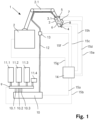
- FIG. 1 an exemplary system 1 for applying a curable building material is shown schematically.
- the system 1 includes a movement device 2 with a movable arm 2.1.
- a print head 3 is attached to the free end of the arm 2.1 and can be moved in all three spatial dimensions by the arm 2.1. The print head 3 can thus be moved to any position in the working area of the movement device 2.
- the print head 3 has an inside facing the arm 2.1 end face (in Fig. 1 above) to the opposite and free end face continuous tubular passage 3.1 for the passage of hardenable building material. At the free end, the passage 3.1 opens into a controllable outlet 4 in the form of a nozzle that can be continuously opened and closed.
- An inlet nozzle 5 for adding an additive opens laterally into the passage 3.1 in an area facing the arm 2.1. If necessary, an additive, for example a rheology aid, can be added to the curable building material moving through the passage 3.1 through the inlet nozzle 5.
- an additive for example a rheology aid
- a static mixer 6 is further arranged in the passage 3.1, which additionally mixes the curable building material and the additive as it flows through.
- a sampling rate of the measuring unit 8 is, for example, 10 Hz.
- a device 7 for venting the curable building material is also attached to the print head 3.
- the device is designed as a vacuum treatment device and makes it possible to reduce the proportion of air in the curable building material.
- a section of the wall of the passage 3.1 can be designed as a gas-permeable membrane, so that air is drawn out of the curable building material by applying a negative pressure outside the passage 3.1.
- the system 1 for applying a curable building material also has a feed device 9, which corresponds on the input side to three containers 11.1, 11.2, 11.3 and an additive reservoir 11.4.
- Each of the three containers 11.1, 11.2, 11.3 contains one component of the curable building material.
- the first component, which is present in the first container 11.1, comprises, for example, cement and aggregates, for example sand and filler.
- the second component, which is present in the second container 11.2, consists, for example, of water.
- the third component present in the third container 11.3 is, for example, a flow agent in the form of a polycarboxylate ether.
- a rheology aid in the form of modified cellulose and/or a microbial polysaccharide is present in the additive reservoir 11.4.
- the feed device 9 On the output side, the feed device 9 has three separate outlets, each of which is connected to one of three inlets 10.1, 10.2, 10.3 of a mixing device 10.
- the feed device 9 also has individually controllable dosing devices (in Fig. 1 not shown), so that the individual components in the individual containers 11.1, 11.2, 11.3 can be dosed individually into the mixing device 10.
- Another outlet of the feed device is connected to the inlet nozzle 5 (in Fig. 1 not shown), so that additives can be conveyed from the additive reservoir 11.4 into the inlet nozzle 5 via a further metering device of the feed device 9.
- the mixing device 10 is designed as a dynamic mixer and, in addition to this, includes an integrated conveying device in the form of a screw conveyor.
- the mixing device the individually metered components are mixed with one another and conveyed into the flexible line 12 attached to the output side of the mixing device.
- the curable building material can be mixed and conveyed continuously.
- the curable building material can be conveyed into the print head 3 and continuously applied through the controllable outlet 4.
- a measuring unit 13 which is integrated into the delivery line 12 in the area between the mixing device 10 and the print head 3.
- the measuring unit contains, for example, an ultrasound transducer, which is designed to determine the flow properties of the curable material.
- a sampling rate of the measuring unit 13 is, for example, 10 Hz.
- a central control unit 14 of the system 1 includes a processor, a memory unit and several interfaces for receiving data and several interfaces for controlling individual components of the system 1.
- the mixing device 10 is connected to the control unit 14 via a first control line 15a, while the feed device is connected to the control unit 14 via a second control line 15b. This allows the individual components in the containers 11.1, 11.2, 11.3 to be metered into the mixing device 10 via the central control unit in accordance with predetermined recipes stored in the control unit and conveyed into the flexible line 12 at adjustable delivery rates.
- controllable outlet 4, the inlet nozzle 5, and the device 7 for venting the curable building material on the print head are each also connected to the control unit 14 via a separate control line 15c, 15d, 15e and can be controlled or monitored by this.
- the movement device 2 is also connected to the control unit 14 via a further control line 15g.
- the movement of the print head 3 can thus be controlled via the control unit 14.
- the measuring unit 8 is connected to the control unit 14 via a data line 15h, so that pressure data recorded in the measuring unit can be transmitted to the control unit 14.
- the measuring unit 13 is connected to the control unit 14 via a data line 15f, so that data recorded in the measuring unit, which characterize the flow properties, can be transmitted to the control unit 14.
- the dry mineral binder composition used as the first component has, for example, the composition described in Table 1.
- Table 1 Composition of the dry binder composition component Weight % in the binder composition Cement CEM I 52.5 25 Metakaolin 4.5 Betoflow ® D 5 Nekafill® 15 20 Sand 0-1mm 42 Denka CSA #20 2 Sika ® ViscoCrete ® -225P 0.25 Carbowet® 4000 0.5 Modified cellulose 0.05 Inorganic thickener 0.10 Superabsorbent 0.1 Aluminum sulfate 0.5
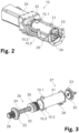
- FIG. 2 is an exemplary embodiment of the mixing device 10 Fig. 1 shown.
- the mixing device 10 comprises a drive 20, a drum 21, a proximal closure 22, a distal closure 23, an outlet 24, a first inlet 10.1, a second inlet 10.2, a third inlet 10.3 and a support device 25.
- the distal closure 23 is connected to the drive 20 via the support device 25, so that a stirring shaft (not visible in this figure) can be stored both in the proximal closure 22 and in the distal closure 23.
- the first component is supplied via the first inlet 10.1, the second component via the second inlet 10.2 and the third component via the third inlet 10.3
- the mixing device 10 is shown without the drive module 20 in a separated state.
- the mixing device 10 comprises a shaft module 26 and a drum module 27.
- the shaft module 26 includes a coupling element 28 for mechanical coupling to the drive unit 20, the proximal closure 22, a stirring shaft 29 and a conveying element 30.
- the drum module 27 comprises an integrally formed tubular drum 31 and a distal closure 23.
- the drum 31 has a first inlet 10.1, a second inlet 10.2 and a third inlet 10.3, all of which are arranged in a first end region of the drum 31 are.
- the outlet 24 is arranged at a second end region of the drum 31.
- the distal closure 23 has a sacrificial plate 32 which is arranged on a side of the distal closure 23 which faces the drum 31.
- the sacrificial plate 32 becomes worn during operation of the system and can be replaced if necessary. This allows the distal closure 23 to be used over a longer period of time.
- the conveying element 30 is designed as a screw conveyor in this exemplary embodiment.
- the conveying element 30 is arranged so that it can be plugged onto the agitator shaft 29.
- the conveying element 30 is secured with a locking element on the agitator shaft 29 (not visible in this illustration).
- pins 33 which protrude radially from the stirring shaft 29 are also fastened as stirring elements (in Fig. 3 only a single pin is shown).
- Fig. 4 illustrates a method using the system 1 according to the invention.
- the dry mineral binder composition from Table 1 (see above) is provided as the first component in the container 11.1.
- Water is placed in container 11.2 as the second component and in container 11.3 a superplasticizer is placed as the third component.
- the components are continuously added to the mixing device 10 via the feed device 9 and mixed there in the next step 43 to obtain a mineral binder composition mixed with water.
- the dry binder composition with the composition given in Table 1 is mixed with such an amount of water in the mixing device 10 that a weight ratio of water to dry binder composition of approximately 0.16 is obtained.
- the superplasticizer is added in such a way that a specified flow limit is reached.
- the mineral binder composition mixed with water corresponds to a hardenable building material in a setting state.
- the prepared binder composition is then fed to the print head 3 via the delivery line 12 in the fourth step 44 using the screw conveyor integrated in the mixing device 10.
- an additive in the form of a rheology aid for example a modified cellulose and/or a microbial polysaccharide, is metered into the prepared binder composition in step 45 via the inlet nozzle 5 and/or the binder composition is vented using the device 7. This means that the chemical and/or physical properties are adjusted if necessary so that specified target values for the flow properties are maintained.
- the binder composition is then applied layer by layer in step 46 via the outlet 4 of the print head, so that the object to be produced is produced.
- All steps in the method 40 including the control of the print head are controlled and monitored with the control unit 14.
- a pipe 2 m high with a diameter of around 600 mm was produced as an example.
- the individual applied layers were approximately 30 mm wide and approximately 10 mm high.
- the horizontal speed of the print head was approximately 40 mm per second.
- the printing of the molded body took 2 hours and 40 minutes.
- the height of the lower layers and the upper layers did not differ by more than 5%.
- the printed molded body had a wavy, very uniform surface with no visible defects. Even after 3 days of storage at 25 ° C and about 40% relative humidity, the molded body showed no visible cracks. About 16 hours after the last layer was applied, the hollow body was lifted onto a transport pallet using carrying straps and a crane without causing any damage to the printed molded body.
- the molded body was destroyed using a heavy hammer and the fragments were analyzed optically.
- the fracture surfaces had a uniform surface, without air pockets or defects.
- the fracture surfaces did not show a preferred orientation, which means that the applied layers had an equally good bond with each other as within the same layer.
- the static mixer 6 can be omitted so that there is neither a static nor a dynamic mixer in the print head.
- one or more further conveying devices can be provided in the conveying line 12 and/or in the print head 3. These can also involve conveying devices other than screw conveyors.
- measuring units in the area of the print head 3 and/or in the delivery line 12 instead of or in addition to the measuring units 8, 13, which, for example, enable temperature measurement. It is also conceivable to completely omit the measuring unit 13 in the delivery line or to integrate it into the print head.
- the mixing device 10 can also have fewer or more inlets so that additional components, which are present in additional containers, can be metered in.
- connections to external sources e.g. to a water connection, can also be present.
- control unit it is also possible to program the control unit differently, for example so that a volume flow through the delivery line 12 and/or the print head 3 is taken into account.
Landscapes
- Engineering & Computer Science (AREA)
- Chemical & Material Sciences (AREA)
- Mechanical Engineering (AREA)
- Structural Engineering (AREA)
- Chemical Kinetics & Catalysis (AREA)
- Architecture (AREA)
- Dispersion Chemistry (AREA)
- Manufacturing & Machinery (AREA)
- Ceramic Engineering (AREA)
- Civil Engineering (AREA)
- Materials Engineering (AREA)
- Curing Cements, Concrete, And Artificial Stone (AREA)
- Processing And Handling Of Plastics And Other Materials For Molding In General (AREA)
- Devices For Post-Treatments, Processing, Supply, Discharge, And Other Processes (AREA)
- Application Of Or Painting With Fluid Materials (AREA)
- Coating Apparatus (AREA)
- Producing Shaped Articles From Materials (AREA)
Priority Applications (1)
| Application Number | Priority Date | Filing Date | Title |
|---|---|---|---|
| EP23200998.5A EP4316760A3 (fr) | 2019-03-15 | 2019-03-15 | Système d'application d'un matériel de construction |
Applications Claiming Priority (2)
| Application Number | Priority Date | Filing Date | Title |
|---|---|---|---|
| EP19163218.1A EP3708320A1 (fr) | 2019-03-15 | 2019-03-15 | Système d'application d'un matériel de construction |
| EP23200998.5A EP4316760A3 (fr) | 2019-03-15 | 2019-03-15 | Système d'application d'un matériel de construction |
Related Parent Applications (1)
| Application Number | Title | Priority Date | Filing Date |
|---|---|---|---|
| EP19163218.1A Division EP3708320A1 (fr) | 2019-03-15 | 2019-03-15 | Système d'application d'un matériel de construction |
Publications (2)
| Publication Number | Publication Date |
|---|---|
| EP4316760A2 true EP4316760A2 (fr) | 2024-02-07 |
| EP4316760A3 EP4316760A3 (fr) | 2024-03-20 |
Family
ID=66048988
Family Applications (3)
| Application Number | Title | Priority Date | Filing Date |
|---|---|---|---|
| EP19163218.1A Ceased EP3708320A1 (fr) | 2019-03-15 | 2019-03-15 | Système d'application d'un matériel de construction |
| EP23200998.5A Pending EP4316760A3 (fr) | 2019-03-15 | 2019-03-15 | Système d'application d'un matériel de construction |
| EP20709584.5A Ceased EP3938160A1 (fr) | 2019-03-15 | 2020-03-09 | Système d'application d'un matériau de construction |
Family Applications Before (1)
| Application Number | Title | Priority Date | Filing Date |
|---|---|---|---|
| EP19163218.1A Ceased EP3708320A1 (fr) | 2019-03-15 | 2019-03-15 | Système d'application d'un matériel de construction |
Family Applications After (1)
| Application Number | Title | Priority Date | Filing Date |
|---|---|---|---|
| EP20709584.5A Ceased EP3938160A1 (fr) | 2019-03-15 | 2020-03-09 | Système d'application d'un matériau de construction |
Country Status (8)
| Country | Link |
|---|---|
| US (1) | US20220152868A1 (fr) |
| EP (3) | EP3708320A1 (fr) |
| BR (1) | BR112021013972A2 (fr) |
| CL (1) | CL2021001900A1 (fr) |
| CO (1) | CO2021013338A2 (fr) |
| MX (1) | MX2021010732A (fr) |
| SG (1) | SG11202107330SA (fr) |
| WO (1) | WO2020187635A1 (fr) |
Families Citing this family (13)
| Publication number | Priority date | Publication date | Assignee | Title |
|---|---|---|---|---|
| DE102020110431A1 (de) | 2020-04-16 | 2021-10-21 | AEDITIVE GmbH | Fertigungssystem zur generativen Herstellung von Bauteilen und Verfahren |
| CN112497422A (zh) * | 2020-11-18 | 2021-03-16 | 康硕(德阳)智能制造有限公司 | 一种陶瓷3d打印机专用送料机构 |
| US20220194850A1 (en) * | 2020-12-17 | 2022-06-23 | Icon Technology, Inc. | Utilizing unprocessed clay in the three dimensional additive printing of mortar onto a building structure |
| US12390955B2 (en) * | 2021-03-26 | 2025-08-19 | James Lyman Reusch | Apparatus for additive manufacturing including a batch mixer for cementitious materials |
| WO2023194299A1 (fr) * | 2022-04-08 | 2023-10-12 | Sika Technology Ag | Détermination de rhéologie en ligne dans des procédés de fabrication additive |
| FR3148931B1 (fr) * | 2023-05-25 | 2025-08-15 | Xtreee | Système d’extrusion de materiau de construction equipé d’un dispositif d’injection d’un retardateur de prise en tete d’impression |
| IT202300013005A1 (it) * | 2023-06-23 | 2024-12-23 | Torino Politecnico | Procedimento e apparato per manifattura additiva di un elemento tridimensionale |
| EP4484102B1 (fr) * | 2023-06-27 | 2026-02-25 | Universitat Politècnica De Catalunya | Système et procédé d'extrusion de matériau cimentaire et système de fabrication additive d'une structure à base de matériau cimentaire |
| WO2025002983A1 (fr) | 2023-06-27 | 2025-01-02 | Universitat Politecnica De Catalunya | Système et procédé d'extrusion de matériau cimentaire et système de fabrication additive d'une structure à base de matériau cimentaire |
| JPWO2025057959A1 (fr) * | 2023-09-11 | 2025-03-20 | ||
| DE102023133277A1 (de) * | 2023-11-28 | 2025-05-28 | Atlas Copco Ias Gmbh | Applikationssystem zum Herstellen einer Mehrkomponentenmischung und zum Ein-/Aufbringen der Mehrkomponentenmischung in/auf einen Gegenstand und Verfahren zum Herstellen einer Mehrkomponentenmischung und Ein-/Aufbringen der Mehrkomponentenmischung in/auf einen Gegenstand |
| DE102023133276A1 (de) * | 2023-11-28 | 2025-05-28 | Atlas Copco Ias Gmbh | Vorrichtung zur Materialbehandlung, Verfahren zur Materialbehandlung und System zur Applikation eines Gemisches |
| CN119748633B (zh) * | 2024-12-25 | 2025-10-31 | 中铁二十局集团房地产开发有限公司 | 一种连续挤压式保温拼装砌块生产设备 |
Citations (1)
| Publication number | Priority date | Publication date | Assignee | Title |
|---|---|---|---|---|
| WO2013064826A1 (fr) | 2011-11-01 | 2013-05-10 | Loughborough University | Procédé et appareil pour l'écoulement de liant hydraulique |
Family Cites Families (19)
| Publication number | Priority date | Publication date | Assignee | Title |
|---|---|---|---|---|
| AT385550B (de) * | 1985-06-20 | 1988-04-11 | Ruzicka Klaus Dipl Ing Dr Tech | Einrichtung zur herstellung von bauteilen od. gebaeuden mittels rechengesteuerten produktionsmaschinen |
| JP2805264B2 (ja) * | 1991-11-07 | 1998-09-30 | 株式会社フジタ | コンクリート打設方法とコンクリート打設装置 |
| ITAN20110062A1 (it) * | 2011-05-19 | 2012-11-20 | Francis Fanelli | Metodo per la realizzazione di strutture edili complesse ed apparato per l'implementazione di tale metodo |
| JP6030185B2 (ja) * | 2014-05-14 | 2016-11-24 | ソク−ムン,キム | 3dプリンティング装置及び方法、これを利用した鉄骨コンクリート構造物の施工方法 |
| KR101616306B1 (ko) * | 2014-06-02 | 2016-04-28 | 조선대학교 산학협력단 | 3차원 인쇄식 시멘트 제품 제조장치 및 그 제조방법 |
| KR20160031578A (ko) * | 2014-09-12 | 2016-03-23 | (주)올리브컴인터내셔날 | 블록 구조물 제조 장치 |
| CN204354263U (zh) * | 2014-12-29 | 2015-05-27 | 中国建筑股份有限公司 | 一种适用于不同粘度的宾汉姆多组分流体混合挤出装置 |
| WO2017005803A1 (fr) * | 2015-07-06 | 2017-01-12 | Ftc 3D Gmbh | Impression en 3d à l'aide d'un matériau d'impression pâteux non homogène |
| US10137679B2 (en) * | 2015-10-29 | 2018-11-27 | Raytheon Company | Material deposition system for additive manufacturing |
| KR20220070330A (ko) * | 2016-03-01 | 2022-05-30 | 시카 테크놀러지 아게 | 혼합기, 건축 재료를 적용하기 위한 시스템 및 건축 재료로부터 건축물을 생산하기 위한 방법 |
| CN105965664B (zh) * | 2016-05-04 | 2018-03-20 | 河海大学 | 一种预应力桩3d打印系统及其使用方法 |
| US10074449B2 (en) * | 2016-06-21 | 2018-09-11 | Raytheon Company | Additively manufactured concrete-bearing radiation attenuation structure |
| DK3260258T3 (da) * | 2016-06-22 | 2019-09-23 | Holcim Technology Ltd | Online-styring af reologien af byggemateriale til 3D-printning |
| KR101815513B1 (ko) * | 2016-07-11 | 2018-01-30 | 서울시립대학교 산학협력단 | 폴리머 시멘트 콘크리트 3d 프린터 및 이를 이용한 구조물 시공방법 |
| RU2754668C2 (ru) * | 2016-12-21 | 2021-09-06 | Сикэ Текнолоджи Аг | Аддитивное производство формованных тел из отверждаемых материалов |
| CN106696050A (zh) * | 2017-01-20 | 2017-05-24 | 中国建筑材料科学研究总院 | 一种3d打印机及其打印方法 |
| BR112020000440B1 (pt) * | 2017-08-09 | 2023-12-26 | Sika Technology Ag | Método para a impressão 3d de composições de aglutinante mineral |
| ES2984331T3 (es) * | 2017-08-09 | 2024-10-29 | Sika Tech Ag | Procedimiento para fabricar una estructura a partir de un material de construcción |
| US10851538B2 (en) * | 2019-03-06 | 2020-12-01 | Icon Technology, Inc. | Systems and methods for the construction of structures |
-
2019
- 2019-03-15 EP EP19163218.1A patent/EP3708320A1/fr not_active Ceased
- 2019-03-15 EP EP23200998.5A patent/EP4316760A3/fr active Pending
-
2020
- 2020-03-09 WO PCT/EP2020/056257 patent/WO2020187635A1/fr not_active Ceased
- 2020-03-09 EP EP20709584.5A patent/EP3938160A1/fr not_active Ceased
- 2020-03-09 SG SG11202107330SA patent/SG11202107330SA/en unknown
- 2020-03-09 BR BR112021013972-9A patent/BR112021013972A2/pt not_active Application Discontinuation
- 2020-03-09 MX MX2021010732A patent/MX2021010732A/es unknown
- 2020-03-09 US US17/439,462 patent/US20220152868A1/en active Pending
-
2021
- 2021-07-19 CL CL2021001900A patent/CL2021001900A1/es unknown
- 2021-10-05 CO CONC2021/0013338A patent/CO2021013338A2/es unknown
Patent Citations (1)
| Publication number | Priority date | Publication date | Assignee | Title |
|---|---|---|---|---|
| WO2013064826A1 (fr) | 2011-11-01 | 2013-05-10 | Loughborough University | Procédé et appareil pour l'écoulement de liant hydraulique |
Also Published As
| Publication number | Publication date |
|---|---|
| EP4316760A3 (fr) | 2024-03-20 |
| US20220152868A1 (en) | 2022-05-19 |
| EP3938160A1 (fr) | 2022-01-19 |
| BR112021013972A2 (pt) | 2021-09-21 |
| MX2021010732A (es) | 2021-09-28 |
| EP3708320A1 (fr) | 2020-09-16 |
| SG11202107330SA (en) | 2021-08-30 |
| WO2020187635A1 (fr) | 2020-09-24 |
| CO2021013338A2 (es) | 2021-10-20 |
| CL2021001900A1 (es) | 2022-04-01 |
Similar Documents
| Publication | Publication Date | Title |
|---|---|---|
| EP4316760A2 (fr) | Système d'application d'un matériel de construction | |
| EP3938159B1 (fr) | Procédé d'application d'un matériau de construction | |
| EP3664980B1 (fr) | Procédé d'impression en 3d de compositions de liant minérales | |
| EP3938212A1 (fr) | Composition de liants minéraux pour l'impression 3d | |
| EP3865280B1 (fr) | Fabrication additive de corps moulés en matériaux durcissables | |
| EP3600811B1 (fr) | Procédé d'application de compositions de liaison minérale contenant des fibres | |
| DE69508695T2 (de) | Nichtabrutschende pumpbare Gussmasse und Verfahren zu deren Auftragung | |
| DE112016005031T5 (de) | Trockene Bauzusammensetzung, die mittels einer Schraubenpumpe feucht sprühbar ist und die ein Bindemittel und einen Füllstoff aus biologischer Quelle enthält und Herstellung und Verwendungen einer solchen Zusammensetzung | |
| DE112017005550T5 (de) | Trockenbaustoffzusammensetzung, die auf nassem Weg mit Hilfe einer Schneckenpumpe spritzbar ist, und umfassend ein Bindemittel und einen biobasierten Füllstoff - Herstellung und Anwendungen einer solchen Zusammensetzung | |
| CH639591A5 (de) | Verfahren zum herstellen und zum spritzen von beton oder moertel. | |
| WO2022117571A1 (fr) | Dispositif et procédé de production de béton, en particulier de béton à haute résistance initiale | |
| EP2152647B2 (fr) | Préparations aqueuses d'accélérateurs de prise modifiés par des polymères et leur utilisation dans le domaine de la construction | |
| DE69902274T2 (de) | Technologisches additiv zur agglomerierung von werfbaren baumaterialien und die verwendung dieser additive in werfbarem mörtel und beton | |
| EP2313351B1 (fr) | Compositions de matériau de construction en poudre contenant du dialkyle éther à chaîne longue | |
| AT505718A1 (de) | Verfahren zur herstellung von leichtbeton | |
| WO2018087099A1 (fr) | Accélérateur de durcissement | |
| DE202005015642U1 (de) | Spachtelmasse mit Leichtzuschlag | |
| EP2465835B1 (fr) | Procédé de fabrication continue de masses de mortier | |
| WO1993023342A1 (fr) | Liant hydraulique pour beton ou mortier | |
| EP1963239A2 (fr) | Utilisation d'un additif comme produit de decoffrage |
Legal Events
| Date | Code | Title | Description |
|---|---|---|---|
| PUAI | Public reference made under article 153(3) epc to a published international application that has entered the european phase |
Free format text: ORIGINAL CODE: 0009012 |
|
| STAA | Information on the status of an ep patent application or granted ep patent |
Free format text: STATUS: THE APPLICATION HAS BEEN PUBLISHED |
|
| AC | Divisional application: reference to earlier application |
Ref document number: 3708320 Country of ref document: EP Kind code of ref document: P |
|
| AK | Designated contracting states |
Kind code of ref document: A2 Designated state(s): AL AT BE BG CH CY CZ DE DK EE ES FI FR GB GR HR HU IE IS IT LI LT LU LV MC MK MT NL NO PL PT RO RS SE SI SK SM TR |
|
| PUAL | Search report despatched |
Free format text: ORIGINAL CODE: 0009013 |
|
| AK | Designated contracting states |
Kind code of ref document: A3 Designated state(s): AL AT BE BG CH CY CZ DE DK EE ES FI FR GB GR HR HU IE IS IT LI LT LU LV MC MK MT NL NO PL PT RO RS SE SI SK SM TR |
|
| RIC1 | Information provided on ipc code assigned before grant |
Ipc: B01F 27/2123 20220101ALI20240213BHEP Ipc: B01F 27/1121 20220101ALI20240213BHEP Ipc: B01F 27/072 20220101ALI20240213BHEP Ipc: B01F 27/07 20220101ALI20240213BHEP Ipc: B01F 25/431 20220101ALI20240213BHEP Ipc: E04G 21/04 20060101ALI20240213BHEP Ipc: B33Y 30/00 20150101ALI20240213BHEP Ipc: B28C 7/02 20060101ALI20240213BHEP Ipc: B28C 5/12 20060101ALI20240213BHEP Ipc: B28B 1/00 20060101AFI20240213BHEP |
|
| STAA | Information on the status of an ep patent application or granted ep patent |
Free format text: STATUS: REQUEST FOR EXAMINATION WAS MADE |
|
| 17P | Request for examination filed |
Effective date: 20240920 |
|
| RBV | Designated contracting states (corrected) |
Designated state(s): AL AT BE BG CH CY CZ DE DK EE ES FI FR GB GR HR HU IE IS IT LI LT LU LV MC MK MT NL NO PL PT RO RS SE SI SK SM TR |
|
| STAA | Information on the status of an ep patent application or granted ep patent |
Free format text: STATUS: EXAMINATION IS IN PROGRESS |
|
| 17Q | First examination report despatched |
Effective date: 20250805 |
|
| STAA | Information on the status of an ep patent application or granted ep patent |
Free format text: STATUS: THE APPLICATION IS DEEMED TO BE WITHDRAWN |