EP4317631A1 - Système modulaire de construction permettant de fabriquer et d'étancher une traversée de conduite - Google Patents
Système modulaire de construction permettant de fabriquer et d'étancher une traversée de conduite Download PDFInfo
- Publication number
- EP4317631A1 EP4317631A1 EP22188045.3A EP22188045A EP4317631A1 EP 4317631 A1 EP4317631 A1 EP 4317631A1 EP 22188045 A EP22188045 A EP 22188045A EP 4317631 A1 EP4317631 A1 EP 4317631A1
- Authority
- EP
- European Patent Office
- Prior art keywords
- mounting plates
- cladding
- wall
- modular system
- cladding tubes
- Prior art date
- Legal status (The legal status is an assumption and is not a legal conclusion. Google has not performed a legal analysis and makes no representation as to the accuracy of the status listed.)
- Withdrawn
Links
- 238000007789 sealing Methods 0.000 title claims abstract description 57
- 238000005253 cladding Methods 0.000 claims abstract description 137
- 239000000463 material Substances 0.000 claims abstract description 41
- 239000012528 membrane Substances 0.000 claims abstract description 30
- 238000000034 method Methods 0.000 claims description 15
- 238000009415 formwork Methods 0.000 claims description 12
- 238000004519 manufacturing process Methods 0.000 claims description 11
- 238000013461 design Methods 0.000 claims description 8
- 239000000779 smoke Substances 0.000 claims description 7
- 238000001514 detection method Methods 0.000 claims description 6
- 230000009969 flowable effect Effects 0.000 claims description 5
- 210000004209 hair Anatomy 0.000 claims description 5
- 230000000295 complement effect Effects 0.000 claims description 4
- 230000001681 protective effect Effects 0.000 claims description 3
- 239000000243 solution Substances 0.000 description 6
- 239000007789 gas Substances 0.000 description 5
- 230000000694 effects Effects 0.000 description 4
- 239000002184 metal Substances 0.000 description 4
- 239000004033 plastic Substances 0.000 description 4
- 229920003023 plastic Polymers 0.000 description 4
- 230000008569 process Effects 0.000 description 4
- 238000000926 separation method Methods 0.000 description 4
- 238000012360 testing method Methods 0.000 description 4
- 230000008901 benefit Effects 0.000 description 3
- 238000010276 construction Methods 0.000 description 3
- 238000002955 isolation Methods 0.000 description 3
- 229920000915 polyvinyl chloride Polymers 0.000 description 3
- 239000004800 polyvinyl chloride Substances 0.000 description 3
- 238000012546 transfer Methods 0.000 description 3
- 230000009471 action Effects 0.000 description 2
- 230000001419 dependent effect Effects 0.000 description 2
- 238000001746 injection moulding Methods 0.000 description 2
- 239000007788 liquid Substances 0.000 description 2
- 229920000642 polymer Polymers 0.000 description 2
- 230000008092 positive effect Effects 0.000 description 2
- 238000005266 casting Methods 0.000 description 1
- 230000000052 comparative effect Effects 0.000 description 1
- 239000002131 composite material Substances 0.000 description 1
- 239000004020 conductor Substances 0.000 description 1
- 238000001816 cooling Methods 0.000 description 1
- 239000006260 foam Substances 0.000 description 1
- -1 heat Substances 0.000 description 1
- 238000003780 insertion Methods 0.000 description 1
- 230000037431 insertion Effects 0.000 description 1
- 238000007689 inspection Methods 0.000 description 1
- 238000009434 installation Methods 0.000 description 1
- 238000009413 insulation Methods 0.000 description 1
- 230000035515 penetration Effects 0.000 description 1
- 239000000565 sealant Substances 0.000 description 1
- 238000003892 spreading Methods 0.000 description 1
- 230000007480 spreading Effects 0.000 description 1
- XLYOFNOQVPJJNP-UHFFFAOYSA-N water Substances O XLYOFNOQVPJJNP-UHFFFAOYSA-N 0.000 description 1
Images


Classifications
-
- E—FIXED CONSTRUCTIONS
- E04—BUILDING
- E04G—SCAFFOLDING; FORMS; SHUTTERING; BUILDING IMPLEMENTS OR AIDS, OR THEIR USE; HANDLING BUILDING MATERIALS ON THE SITE; REPAIRING, BREAKING-UP OR OTHER WORK ON EXISTING BUILDINGS
- E04G15/00—Forms or shutterings for making openings, cavities, slits, or channels
- E04G15/06—Forms or shutterings for making openings, cavities, slits, or channels for cavities or channels in walls of floors, e.g. for making chimneys
- E04G15/061—Non-reusable forms
-
- F—MECHANICAL ENGINEERING; LIGHTING; HEATING; WEAPONS; BLASTING
- F16—ENGINEERING ELEMENTS AND UNITS; GENERAL MEASURES FOR PRODUCING AND MAINTAINING EFFECTIVE FUNCTIONING OF MACHINES OR INSTALLATIONS; THERMAL INSULATION IN GENERAL
- F16L—PIPES; JOINTS OR FITTINGS FOR PIPES; SUPPORTS FOR PIPES, CABLES OR PROTECTIVE TUBING; MEANS FOR THERMAL INSULATION IN GENERAL
- F16L5/00—Devices for use where pipes, cables or protective tubing pass through walls or partitions
- F16L5/02—Sealing
- F16L5/04—Sealing to form a firebreak device
-
- F—MECHANICAL ENGINEERING; LIGHTING; HEATING; WEAPONS; BLASTING
- F16—ENGINEERING ELEMENTS AND UNITS; GENERAL MEASURES FOR PRODUCING AND MAINTAINING EFFECTIVE FUNCTIONING OF MACHINES OR INSTALLATIONS; THERMAL INSULATION IN GENERAL
- F16L—PIPES; JOINTS OR FITTINGS FOR PIPES; SUPPORTS FOR PIPES, CABLES OR PROTECTIVE TUBING; MEANS FOR THERMAL INSULATION IN GENERAL
- F16L5/00—Devices for use where pipes, cables or protective tubing pass through walls or partitions
- F16L5/02—Sealing
- F16L5/14—Sealing for double-walled or multi-channel pipes
-
- H—ELECTRICITY
- H02—GENERATION; CONVERSION OR DISTRIBUTION OF ELECTRIC POWER
- H02G—INSTALLATION OF ELECTRIC CABLES OR LINES, OR OF COMBINED OPTICAL AND ELECTRIC CABLES OR LINES
- H02G3/00—Installations of electric cables or lines or protective tubing therefor in or on buildings, equivalent structures or vehicles
- H02G3/22—Installations of cables or lines through walls, floors or ceilings, e.g. into buildings
Definitions
- the invention relates to a modular building block system and an associated method for producing and sealing a cable bushing, for example for cables or pipes that are to be guided through a wall.
- the wall can be, for example, a side wall, ceiling or floor of a building.
- this can be a fire protection sealing of the line bushing, in particular against smoke gases and/or against heat transfer.
- pouring devices and fire protection cable boxes are known in the prior art for the isolation, ie fire protection sealing, of pipe or cable penetrations through a building wall. They usually include a bushing that is concreted into a wall section or a wall opening to be produced (casting devices) or can be installed in some other way in order to close it close and thereby form a passageway for the passage of lines such as cables or pipes.
- the duct must generally be sufficiently sealed against smoke, heat, gases and other media that may form in the building in the event of a fire. This is intended to largely prevent the fire and harmful fire products such as smoke and gases from spreading from an affected room to other rooms through the cable feedthrough.
- So-called sleeves are often used in the area of cable bushings.
- Very simple sleeves consist of a metal cladding tube that is used to form a recess in the form of a through opening when concreting the wall, as well as a sealant to seal the cables that are routed through this recess.
- More efficient sleeve solutions usually consist of a metal frame with fire protection and sealing functions. These sleeves are usually inserted into a through opening provided therein after the raw concrete wall or raw concrete ceiling has been completed and are subsequently attached and sealed, for example by means of a mounting frame.
- the problem is usually that a relatively large sleeve or box is used in relation to the diameter of an individual line (such as a cable or pipe).
- This sleeve/box is usually designed to be universal and is designed to accommodate as many cables/pipes as possible, but it must also function sealingly in the case of a so-called zero occupancy.
- the fire protection measures used are designed for the maximum range of application areas and are therefore oversized in most cases.
- the largest uniform sleeve must be used, which is designed for around a dozen different cables with varying diameters, even if only a few cables are to be laid.
- the cable bushing can in particular concern electrical cables, but also pipes or other types of cables that are to be routed through a fire compartment.
- the cable bushing can be created in particular in a (concrete) wall to be manufactured or a wall opening to be closed.
- the wall can be, for example, a side wall, ceiling or floor of a building. In particular, this can be a fire protection sealing of the line bushing, in particular against smoke gases and/or against heat transfer.
- a modular system for producing and sealing a line bushing.
- the problems mentioned at the beginning and the tasks mentioned above can be solved.
- the user can thus adapt the cable bushing individually to his needs, for example with regard to the number and diameter of the cables to be passed through and sealed, while maintaining the reliable sealing function and simplicity of producing and sealing the cable bushing.
- the modular building block system includes the following two types of components, which are ideally available in different sizes:
- the modular system comprises several cladding tubes, ie elongated cylindrical hollow bodies, with each cladding tube forming an axial passage channel in its longitudinal direction for the passage of an individual line.
- the passage channel is closed by a sealing element on one or both end faces of the cladding tube.
- the sealing element has a pierceable sealing membrane which is designed to be pierced by a single line (cable or pipe) when it is inserted into the passage and to seal the pierced line again from all sides, without any further action.
- the sealing membrane can be made from any material suitable for this functionality, in particular elastically stretchable, such as soft PVC (polyvinyl chloride), rubber, etc., with a thickness selected depending on the respective diameters of the cladding tube and the line to be pierced.
- the cladding tubes can basically have any cross-sectional shape, in particular circular, oval, or polygonal, in particular rectangular.
- the cladding tubes can be provided in the modular system, in particular with several different cladding tube diameters and/or cross-sectional shapes, in order to be suitable for lines of different line diameters and/or cross-sectional shapes.
- the correct choice of a suitable cladding tube that ensures the function described above can be ensured, for example, by provided tables or labels on the cladding tubes that indicate suitable line diameters and/or materials, especially for inexperienced users.
- the modular system comprises several mounting plates (also referred to as base plates), in particular similar or identical pairs and/or edge to edge that can be connected to one another to form an enlarged area.
- Each mounting plate has one or more recesses.
- Each recess is designed to accommodate and at least temporarily fix one of the cladding tubes from the modular system with an outer diameter corresponding to the recess and a corresponding cross-sectional shape.
- the recesses are usefully designed to position and fix the cladding tubes with their axis essentially perpendicular to a mounting plate surface or mounting plate plane.
- the recesses can be designed in particular as through holes, in the case of reusable mounting plates that have to be removed after the cable bushing has been manufactured, but alternatively also as blind holes etc.
- a mounting plate has several recesses, these are arranged and designed in relation to the radial outer dimensions of the associated cladding tubes in such a way that a radial distance and thus an intermediate space remains between the cladding tubes, which are fixed to directly adjacent recesses, which is in particular due to a flowable Wall-creating material (such as concrete, etc.) can be filled in when making a wall or closing a wall opening.
- a flowable Wall-creating material such as concrete, etc.
- the modular system can comprise a plurality of mounting plates, which can be fastened to one another edge to edge to form a surface-mounted mounting plate and have recesses of the same or different design from mounting plate to mounting plate, each with the same or different number and/or arrangement.
- the recesses in the individual mounting plates are arranged and designed in relation to the radial outer dimensions of the associated cladding tubes in such a way that there is a radial distance and thus a gap between the cladding tubes, which are fixed to directly adjacent recesses of two interconnected mounting plates Filling with a flowable wall-creating material (such as concrete, etc.) remains. This can, for example, contribute to ensuring sufficient cooling and/or external sealing of the cladding tubes.
- the main function of the mounting plates is the positioning of the cladding pipes before and during the construction of the wall or when closing a wall opening in which the cable bushing is to be created.
- the mounting plate with cladding tubes fixed to it can be attached, for example, to a formwork that is used to pour and harden a flowable wall-creating material (in particular concrete) for the respective wall section.
- the mounting plates for example together with the formwork, can be removed from the finished wall section and reused.
- the mounting plates can be permanently in place Wall or concrete ceiling remains.
- the mounting plates can be manufactured as simply as possible and with as little material as possible, for example from a recycled material.
- the mounting plates can be made, for example, from plastic or metal or any other material suitable for the functionality described herein.
- each line to be laid has its own cladding tube with at least one sealing membrane that can be pierced by this line, which is therefore able to seal the individual line from all sides without gaps.
- each cladding tube is surrounded by it.
- each cable can be cooled significantly better via its own, appropriately dimensioned cladding tube, for example in the event of a fire or other heat transfer, than, for example, an entire cable bundle in a single sleeve, where individual cables in the bundle have significantly less contact with the surrounding cool concrete (or another wall-creating material) can be realized.
- the user typically has an electrical plan showing which cables and other lines should or can be routed through which walls before individual walls are erected in the building.
- the user of the modular system for example an electrician, can prepare the cable routes and conductor routes accordingly during installation work in advance of the direction of travel by selecting the appropriate empty cladding tubes from the modular system and using the appropriate mounting plates as described herein positioned and laid in the required wall section by pouring or setting in concrete.
- the user can individually design the design of the cable bushing with regard to the number, size and mutual arrangement of individual passage channels/sheathing pipes for individual cables using the modular system and adapt it flexibly to their specific wishes and requirements.
- At least some of the mounting plates of the modular system each have at least one connecting element for fastening to one another. This allows the assembled mounting plates to be fixed next to one another in a suitable arrangement, in particular to ensure predetermined suitable distances for the cladding tubes attached thereto and/or to obtain a stable and/or compact assembly.
- each of these mounting plates can have at least two connecting elements which are designed to be complementary to one another and which are designed and arranged in the same way in each mounting plate, so that connecting elements of two mounting plates can be brought into a positive fit by interlocking in order to fasten them to one another .
- modularity of the modular system can be achieved in a particularly simple manner, in which, for example, all mounting plates can be connected to one another in any combination to form a composite mounting plate with an enlarged area and number of recesses.
- This type of connecting element can also be particularly simple with regard to the production of the modular system and/or handling during assembly.
- the recesses can be designed as through openings in the mounting plates.
- the associated cladding tubes can be at least partially inserted into the respective recess in order to fix them on the mounting plate.
- the passage channel of the respective cladding tube can remain uncovered by the mounting plate, so that the mounting plate can remain in the wall, for example, even after the wall section with the cable bushing has been completed (disposable mounting plate).
- At least some of the cladding tubes have a circumferential shoulder on the outside at least at one of their two ends, which can be formed, for example, by a recess extending from the end face of the cladding tube to the shoulder or by a radial projection.
- the shoulder is arranged at a predetermined axial shoulder distance from the end face of the cladding tube, and the associated recesses in the mounting plates have an inner diameter which essentially corresponds precisely to an outer diameter of such an associated cladding tube in its axial end section beyond the shoulder.
- the cladding tube can be inserted into the recess up to the stop on its shoulder, which, in addition to significantly simplifying the assembly process, also increases the robustness and / or the precision of the positioning of the cladding tubes on the mounting plates.
- the cladding tubes can have at least one intumescent element on the inside and/or outside, which can be designed to comply with predetermined fire protection measures.
- the intumescent element can be designed, for example, as a circumferential strip made of or with an intumescent material, that is, which foams under the influence of heat and additionally closes the passage channel on the inside or outside.
- the outside intumescent element can in particular be arranged at a predetermined axial undercut distance from the respective end face or possibly from the above-mentioned shoulder of the cladding tube in order to form an undercut in the wall-creating material (concrete, etc.) that will be filled in later.
- the respective sealing membrane can be arranged in its non-pierced state with a predetermined axial membrane offset from the associated end face in the cladding tube.
- At least one of the mounting plates can have one or more fastening elements for at least temporarily fastening the mounting plate to a wall forming formwork.
- a fastening element can be designed as a through hole for receiving a connecting body such as a nail, a screw or a bolt.
- At least some of the cladding tubes can have, at least at one of their two ends, a detection element which extends axially beyond the end face of the cladding tube by a predetermined length, in particular in the form of detection hairs attached to the cladding tube in a brush-like manner.
- at least one of the mounting plates can also have in an edge region of its surface at least one locating element which projects out of the mounting plate surface by a predetermined length, in particular in the form of locating hairs attached to the mounting plate in a brush-like manner.
- locating elements can make it easier to locate the cable bushing after the assembly has been cast in a wall.
- the cladding tubes on the one hand and the associated recesses in the mounting plates on the other hand are like this designed so that the respective cladding tube, in its fixed state on the mounting plate, does not protrude axially beyond a mounting plate surface facing away from the cladding tube.
- this mounting plate surface can even protrude above the end face of the cladding tube fixed to it by a predetermined axial protective offset.
- the modular system can be designed to produce and seal a line bushing against smoke and/or fire and/or other media such as heat and water, which could otherwise get from room to room via the line bushing, for example in the event of a fire or other accident situations.
- This can be achieved through individual features of the modular system, which are described herein, in combination with a suitable choice of materials and/or with further protective measures and elements for fire protection.
- pairs of identical mounting plates can be selected for assembly and the cladding tubes can be attached at both ends to the associated recesses of the pairs of identical mounting plates before the wall-generating material is poured into the wall-generating structure.
- This allows for a particularly stable one Create an assembly from two identical mounting plate arrangements and cladding tubes fixed between them.
- the mounting plates are removed from at least one of the two ends of the cladding pipes cast in the wall after the wall has been created and the cable bushing cast into it.
- this is not mandatory, i.e. H.
- the mounting plates can remain in it after the wall has been completed and thereby further stabilize the cladding pipes in addition to the concrete etc.
- a cable bushing is provided in a wall which was produced by a method presented herein. If the line bushing has several cladding tubes, the individual cladding tubes are each completely separated from one another by gaps which are filled with solidified wall-creating material such as concrete, etc. and/or possibly other types of filling or fire protection material.
- each cladding tube After being poured into concrete, each cladding tube is surrounded by it. This allows the cladding tube (as a type of single bushing) to be better cooled by the surrounding cool concrete than a bundle of cables in a prior art fire protection cable box, which has little contact with the surrounding cool concrete.
- Another important advantage that results from the concept presented here is that, for example, a tightness of almost 100% can be achieved in ceiling ducts. A chimney effect known from conventional arrangements with continuous heat transport through the cable bushing can therefore be prevented with the modular system presented here and its sealing concept.
- each cladding tube remains cool for longer under the same test conditions, and the sealing elements on the tops or ends of each cladding tube are also exposed to less high temperatures.
- good temperature resistance is therefore significantly less critical than with conventional systems.
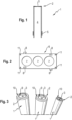
- Fig. 1 shows a longitudinal section of an example of a single cladding tube 1 as part of a modular building block system (also called building block for short) according to the first aspect of the invention.
- the modular system can include several such and differently designed cladding tubes 1 with different diameter sizes (cf. Fig. 3 ).
- the cladding tube 1 has a sealing element 2 at one of its two ends with a line (only in Fig. 10 shown) sealing membrane 3 to be penetrated, for example made of soft PVC, rubber, etc.
- the sealing membrane 3 closes the passage channel 4 formed by the cladding tube 1 and thereby seals it.
- an intumescent element 5 in the form of a circumferential intumescent fire protection tape is provided on the outside at another end of the cladding tube 1.
- Fig. 2 shows a top view of an example of a rectangular mounting plate 6 made of plastic or metal etc., which is also part of a modular building block system according to the first aspect of the invention.
- the mounting plate 6 has three identical circular recesses 7, each for receiving and at least temporarily fixing a cladding tube 1, for example Fig. 1 , are formed with a cross section and outer diameter corresponding to the recess 7.
- the modular system can include several mounting plates 6 of the same and/or different design with recesses 7, each with the same or different number, size and/or arrangement, which can in particular be connectable to one another to form modular mounting plates (cf. Fig. 4-5 ).
- the mounting plate 6 has two connecting elements 8 on each of its two long edges which are designed to complement one another and which are also designed and arranged in the same way in every other mounting plate 6 of the modular system (cf. Figs. 4 and 5 ), so that connecting elements 8 of two mounting plates 6 are to be brought into a positive fit by interlocking in order to attach them to one another, as in Figs. 4 and 5 shown.
- the mounting plate 6 has an optional fastening element 11 in each of its corners for at least temporary fastening to a wall forming formwork, for example a concrete formwork 12 Fig. 8 .
- each fastening element 11 is designed as a through hole for receiving a connecting body such as a nail, a screw or a bolt for fastening the mounting plate 6 on the concrete formwork 12 (cf. Fig. 8 ).
- Fig. 3 shows in a perspective view, purely by way of example, three or more cladding tubes 1 of the modular system according to an embodiment of the invention with partly the same and partly different diameters.
- the sealing membrane 3 is arranged in its non-pierced state with a predetermined axial membrane offset 9 from the associated end face 10 in the cladding tube 1.
- Fig. 4 shows a top view of an arrangement of two identical rectangular mounting plates 6 similar to that Fig. 2 , which were fastened to each other edge to edge by means of pairs of complementary connecting elements 8.
- Fig. 5 shows, also in a top view, another example of a total of five rectangular mounting plates 6 connected to one another in this way according to an embodiment of the invention with partly the same and partly different sizes and arrangements of the recesses 7. Otherwise, the same applies here as in relation to Fig. 4 described.
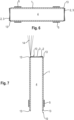
- Fig. 6 shows a longitudinal section of another example of a cladding tube 1 of the modular system according to an embodiment of the invention, which can be used, for example, for a cable feedthrough in a side wall of a building. It differs from the cladding tube 1 Fig. 1 only in that it has an external intumescent element 5 at both ends in the form of a circumferential intumescent fire protection tape (also called intumescent strip) and a sealing element 2 with a sealing membrane 3, which seals the passage channel, as well as circumferential shoulders 13, which are described below with reference to Fig. 7 to be discribed.
- an external intumescent element 5 at both ends in the form of a circumferential intumescent fire protection tape (also called intumescent strip) and a sealing element 2 with a sealing membrane 3, which seals the passage channel, as well as circumferential shoulders 13, which are described below with reference to Fig. 7 to be discribed.
- Fig. 7 shows a longitudinal section of another example of a cladding tube 1 of the modular system according to an embodiment of the invention. It differs from the cladding tube 1 Fig. 1 on the one hand, in that it has a circumferential shoulder 13 at both ends for improved connection to the mounting plates 6 of the modular system.
- the shoulder 13 is formed by a recess extending from the respective end face 10 of the cladding tube 1 to the shoulder 13 and serves to limit the depth when mounting the cladding tube 1 on a mounting plate 6.
- the intumescent element 5 is arranged in such a way (here at a predetermined axial undercut distance from the end face 10 and from the shoulder 13) that an undercut can be created in the concrete when it is set in concrete.
- the cladding tube has 1 in Fig. 7 a detection element 14 which extends axially beyond the end face or end face 10 of the cladding tube 1 by a predetermined length, here in the form of brush-like hairs (English: whiskers) molded onto the cladding tube 1.
- a detection element 14 which extends axially beyond the end face or end face 10 of the cladding tube 1 by a predetermined length, here in the form of brush-like hairs (English: whiskers) molded onto the cladding tube 1.
- Fig. 8 shows a perspective view of an assembly 15 (also called a module), which can be present in a method according to the invention described above and in the claims shortly before the wall-creating material (here concrete) is poured into the concrete formwork 12.
- the assembly comprises two identical mounting plates, each made up of four individual mounting plates 6, each with three or four recesses 7 of different sizes by connecting edge to edge, similar to Fig. 5 , between which in this example eight cladding tubes 1 are positioned and fixed in the recesses 7, each of a different size.
- the lower of the two assembled mounting plates is temporarily attached to the formwork 12 by means of the fastening elements 11 (through holes with nails) for the period of concreting.
- the fastening elements 11 through holes with nails
- Fig. 9 shows a longitudinal section of an example of a line bushing 16 embedded in concrete in a wall 17 (here a ceiling), which was produced by a method according to the second aspect of the invention, before the introduction of lines 18 (such as cables or pipes, see Fig. 10 ).
- the cable bushing 16 has three passage channels in this longitudinal section, which are each intended for one line (cf. Fig. 10 ).
- an assembly 15 similar to that in Fig. 8 as well as their individual elements similar to Fig. 2 to Fig. 7 are used, so that their repeated description is omitted.
- all passage channels 4 are tightly closed by their sealing membranes 3.
- Fig. 10 shows a longitudinal section of the cable bushing 16 concreted into the wall 17 Fig. 9 after laying lines 18 in their two of three passage channels 4, which are visible in this sectional view.
- the "thicker" line 18 left in Fig. 10
- thinner line 18 was installed from the underside of the ceiling:
- the respective sealing membrane 3 was pierced through the line 18 and now seals it as shown by being tightly attached to it from all sides Line 18 nestles.
- the top side can also be designed to be more robust in order to prevent damage to the sealing membranes 3.
- the sealing membrane 3 of the cladding tube 1 can be arranged slightly recessed into it (cf. Fig. 3 and associated description) so that it is not damaged.
- the mounting plate 6 can be designed so that it protrudes slightly beyond each cladding tube 1 fixed to it (not shown). When there is contact with the power trowel, only the mounting plate 6, but not the membrane 3, is touched.
Landscapes
- Engineering & Computer Science (AREA)
- Architecture (AREA)
- General Engineering & Computer Science (AREA)
- Mechanical Engineering (AREA)
- Civil Engineering (AREA)
- Structural Engineering (AREA)
- Installation Of Indoor Wiring (AREA)
Priority Applications (5)
| Application Number | Priority Date | Filing Date | Title |
|---|---|---|---|
| EP22188045.3A EP4317631A1 (fr) | 2022-08-01 | 2022-08-01 | Système modulaire de construction permettant de fabriquer et d'étancher une traversée de conduite |
| CA3258996A CA3258996A1 (fr) | 2022-08-01 | 2023-07-11 | Système modulaire pour la production et l’étanchéification d’un passage de conduites |
| AU2023318447A AU2023318447A1 (en) | 2022-08-01 | 2023-07-11 | Modular system for producing and sealing a line feedthrough |
| PCT/EP2023/069149 WO2024028047A1 (fr) | 2022-08-01 | 2023-07-11 | Système de kit de construction modulaire pour produire et sceller un passage de câble ou de tuyau |
| EP23741644.1A EP4565759A1 (fr) | 2022-08-01 | 2023-07-11 | Système de kit de construction modulaire pour produire et sceller un passage de câble ou de tuyau |
Applications Claiming Priority (1)
| Application Number | Priority Date | Filing Date | Title |
|---|---|---|---|
| EP22188045.3A EP4317631A1 (fr) | 2022-08-01 | 2022-08-01 | Système modulaire de construction permettant de fabriquer et d'étancher une traversée de conduite |
Publications (1)
| Publication Number | Publication Date |
|---|---|
| EP4317631A1 true EP4317631A1 (fr) | 2024-02-07 |
Family
ID=82786282
Family Applications (2)
| Application Number | Title | Priority Date | Filing Date |
|---|---|---|---|
| EP22188045.3A Withdrawn EP4317631A1 (fr) | 2022-08-01 | 2022-08-01 | Système modulaire de construction permettant de fabriquer et d'étancher une traversée de conduite |
| EP23741644.1A Pending EP4565759A1 (fr) | 2022-08-01 | 2023-07-11 | Système de kit de construction modulaire pour produire et sceller un passage de câble ou de tuyau |
Family Applications After (1)
| Application Number | Title | Priority Date | Filing Date |
|---|---|---|---|
| EP23741644.1A Pending EP4565759A1 (fr) | 2022-08-01 | 2023-07-11 | Système de kit de construction modulaire pour produire et sceller un passage de câble ou de tuyau |
Country Status (4)
| Country | Link |
|---|---|
| EP (2) | EP4317631A1 (fr) |
| AU (1) | AU2023318447A1 (fr) |
| CA (1) | CA3258996A1 (fr) |
| WO (1) | WO2024028047A1 (fr) |
Citations (13)
| Publication number | Priority date | Publication date | Assignee | Title |
|---|---|---|---|---|
| DE9002185U1 (de) * | 1990-02-23 | 1991-07-18 | Thyssen Polymer GmbH, 8000 München | Abdichtelement |
| DE60007331T2 (de) * | 1999-09-06 | 2004-06-03 | Alain Genoud | Element für giessvorgang |
| DE10331743A1 (de) | 2003-07-11 | 2005-02-10 | Martin Reuter | Brandschott |
| US20070283644A1 (en) | 2006-04-19 | 2007-12-13 | Marco Fischer | Leadthrough for a conduit |
| CN201536237U (zh) | 2009-11-24 | 2010-07-28 | 鞍钢集团矿业公司 | 建筑物内敷设电缆的防火装置 |
| US8336833B2 (en) * | 2009-05-15 | 2012-12-25 | M.A. Industries, Inc. | Modular grid system |
| US20140020315A1 (en) | 2012-07-23 | 2014-01-23 | Hilti Aktiengesellschaft | Assembly for a line conduit |
| FR3012493A1 (fr) * | 2013-10-31 | 2015-05-01 | Rector Internat | Boitier de reservation pour element de construction, notamment pour plancher, et element de construction comportant un tel boitier de reservation |
| US20160123002A1 (en) | 2013-07-17 | 2016-05-05 | Hilti Aktiengesellschaft | Through-Penetration Device, Method for Manufacturing a Through-Penetration Device, and Method for Installing a Through-Penetration Device |
| WO2017198591A1 (fr) * | 2016-05-18 | 2017-11-23 | Hilti Aktiengesellschaft | Élément ignifuge ainsi que procédé de fabrication d'un élément ignifuge |
| US20190120409A1 (en) | 2016-04-12 | 2019-04-25 | Hilti Aktiengesellschaft | Method for producing an assembly for a line penetration, assembly and method for production of a line penetration |
| WO2020141386A1 (fr) * | 2019-01-04 | 2020-07-09 | Detas S.P.A. | Dispositif guide-câble conçu pour retenir et guider des câbles |
| CA3098232A1 (fr) * | 2020-01-24 | 2021-07-24 | Ipex Technologies Inc. | Dispositif moule en place |
Family Cites Families (1)
| Publication number | Priority date | Publication date | Assignee | Title |
|---|---|---|---|---|
| DE102011088487A1 (de) * | 2011-12-14 | 2013-06-20 | Hilti Aktiengesellschaft | Modulrahmen zur Befestigung einer Leitungsdurchführung an einem Bauteil |
-
2022
- 2022-08-01 EP EP22188045.3A patent/EP4317631A1/fr not_active Withdrawn
-
2023
- 2023-07-11 CA CA3258996A patent/CA3258996A1/fr active Pending
- 2023-07-11 WO PCT/EP2023/069149 patent/WO2024028047A1/fr not_active Ceased
- 2023-07-11 EP EP23741644.1A patent/EP4565759A1/fr active Pending
- 2023-07-11 AU AU2023318447A patent/AU2023318447A1/en active Pending
Patent Citations (14)
| Publication number | Priority date | Publication date | Assignee | Title |
|---|---|---|---|---|
| DE9002185U1 (de) * | 1990-02-23 | 1991-07-18 | Thyssen Polymer GmbH, 8000 München | Abdichtelement |
| DE60007331T2 (de) * | 1999-09-06 | 2004-06-03 | Alain Genoud | Element für giessvorgang |
| DE10331743A1 (de) | 2003-07-11 | 2005-02-10 | Martin Reuter | Brandschott |
| US20070283644A1 (en) | 2006-04-19 | 2007-12-13 | Marco Fischer | Leadthrough for a conduit |
| US8336833B2 (en) * | 2009-05-15 | 2012-12-25 | M.A. Industries, Inc. | Modular grid system |
| CN201536237U (zh) | 2009-11-24 | 2010-07-28 | 鞍钢集团矿业公司 | 建筑物内敷设电缆的防火装置 |
| US20140020315A1 (en) | 2012-07-23 | 2014-01-23 | Hilti Aktiengesellschaft | Assembly for a line conduit |
| US9074367B2 (en) * | 2012-07-23 | 2015-07-07 | Hilti Aktiengesellschaft | Assembly for a line conduit |
| US20160123002A1 (en) | 2013-07-17 | 2016-05-05 | Hilti Aktiengesellschaft | Through-Penetration Device, Method for Manufacturing a Through-Penetration Device, and Method for Installing a Through-Penetration Device |
| FR3012493A1 (fr) * | 2013-10-31 | 2015-05-01 | Rector Internat | Boitier de reservation pour element de construction, notamment pour plancher, et element de construction comportant un tel boitier de reservation |
| US20190120409A1 (en) | 2016-04-12 | 2019-04-25 | Hilti Aktiengesellschaft | Method for producing an assembly for a line penetration, assembly and method for production of a line penetration |
| WO2017198591A1 (fr) * | 2016-05-18 | 2017-11-23 | Hilti Aktiengesellschaft | Élément ignifuge ainsi que procédé de fabrication d'un élément ignifuge |
| WO2020141386A1 (fr) * | 2019-01-04 | 2020-07-09 | Detas S.P.A. | Dispositif guide-câble conçu pour retenir et guider des câbles |
| CA3098232A1 (fr) * | 2020-01-24 | 2021-07-24 | Ipex Technologies Inc. | Dispositif moule en place |
Also Published As
| Publication number | Publication date |
|---|---|
| WO2024028047A1 (fr) | 2024-02-08 |
| EP4565759A1 (fr) | 2025-06-11 |
| CA3258996A1 (fr) | 2025-03-21 |
| AU2023318447A1 (en) | 2024-12-12 |
Similar Documents
| Publication | Publication Date | Title |
|---|---|---|
| EP0388797B1 (fr) | Faisceau de conduits de câble comprenant une pluralité de tuyaux en matière synthétique | |
| EP2604899B1 (fr) | Cadre de module pour fixation d'un passage de conduite sur un composant | |
| DE3000670A1 (de) | Feuersichere leitungsdurchfuehrung | |
| DE2936846A1 (de) | Verfahren zum feuergesicherten verschliessen einer durchdringung fuer eine leitung in einem gebaeudeteil und vorrichtung zur durchfuehrung des verfahrens | |
| DE2727286A1 (de) | Verfahren und vorrichtung zum verbinden flaechenfoermiger bauelemente | |
| EP2763256A2 (fr) | Canal de câbles avec passage de paroi, kit de passage de paroi et procédé de montage d'un passage de paroi pour un canal de câbles | |
| EP2273170A1 (fr) | Semelle de coffrage pour passage de mur | |
| DE8904670U1 (de) | Kabeldurchführung | |
| DE202006006361U1 (de) | Einbettbare Vorrichtung zum Durchführen von Leitungen durch ein Bauteil | |
| DE2936640A1 (de) | Baustein und bauverfahren | |
| EP2511580B2 (fr) | Passage destiné à l'intégration dans un élément de paroi ou de sol | |
| DE2829887C2 (de) | Verfahren zur Herstellung von wasserdichten und feuerfesten Kabeldurchführungen | |
| EP4317631A1 (fr) | Système modulaire de construction permettant de fabriquer et d'étancher une traversée de conduite | |
| EP2146004A2 (fr) | Connexion de broche travaillant en cisaillement | |
| EP4397820B1 (fr) | Unité de raccordement pour un drainage de toit comprenant un cadre de raccordement | |
| EP2806516A1 (fr) | Bloc d'étanchéité pour des conducteurs individuels | |
| EP3246613A1 (fr) | Panneau coupe-feu et caisson modulaire | |
| EP2716829B1 (fr) | Support d'appareil | |
| EP0224008A2 (fr) | Ensemble pour la construction de canalisations de câbles retardant le feu | |
| DE19735957A1 (de) | Verfahren und Vorrichtung zum Herstellen von Bauelementen sowie danach hergestellte Bauelemente mit Vorinstallation | |
| DE10228255C1 (de) | Fassadendose | |
| DE202021101571U1 (de) | Einsatzmodul für ein Wandelement und Wandelement mit Einsatzmodul | |
| DE102021006393A1 (de) | Hausdurchführung zum Durchführen wenigstens einer Leitung durch eine Bodenplatte und Bodenplatte mit selbiger | |
| DE102021114304B4 (de) | Schalungselement | |
| EP2937493A1 (fr) | Passage encastrable dans un élément de mur ou de sol |
Legal Events
| Date | Code | Title | Description |
|---|---|---|---|
| PUAI | Public reference made under article 153(3) epc to a published international application that has entered the european phase |
Free format text: ORIGINAL CODE: 0009012 |
|
| STAA | Information on the status of an ep patent application or granted ep patent |
Free format text: STATUS: THE APPLICATION HAS BEEN PUBLISHED |
|
| AK | Designated contracting states |
Kind code of ref document: A1 Designated state(s): AL AT BE BG CH CY CZ DE DK EE ES FI FR GB GR HR HU IE IS IT LI LT LU LV MC MK MT NL NO PL PT RO RS SE SI SK SM TR |
|
| STAA | Information on the status of an ep patent application or granted ep patent |
Free format text: STATUS: THE APPLICATION IS DEEMED TO BE WITHDRAWN |
|
| 18D | Application deemed to be withdrawn |
Effective date: 20240808 |