EP4317659A1 - Moteur à turbine à gaz avec troisième flux - Google Patents
Moteur à turbine à gaz avec troisième flux Download PDFInfo
- Publication number
- EP4317659A1 EP4317659A1 EP23183581.0A EP23183581A EP4317659A1 EP 4317659 A1 EP4317659 A1 EP 4317659A1 EP 23183581 A EP23183581 A EP 23183581A EP 4317659 A1 EP4317659 A1 EP 4317659A1
- Authority
- EP
- European Patent Office
- Prior art keywords
- fan
- gas turbine
- turbine engine
- airflow
- ratio
- Prior art date
- Legal status (The legal status is an assumption and is not a legal conclusion. Google has not performed a legal analysis and makes no representation as to the accuracy of the status listed.)
- Pending
Links
Images





Classifications
-
- F—MECHANICAL ENGINEERING; LIGHTING; HEATING; WEAPONS; BLASTING
- F02—COMBUSTION ENGINES; HOT-GAS OR COMBUSTION-PRODUCT ENGINE PLANTS
- F02K—JET-PROPULSION PLANTS
- F02K3/00—Plants including a gas turbine driving a compressor or a ducted fan
- F02K3/02—Plants including a gas turbine driving a compressor or a ducted fan in which part of the working fluid by-passes the turbine and combustion chamber
- F02K3/04—Plants including a gas turbine driving a compressor or a ducted fan in which part of the working fluid by-passes the turbine and combustion chamber the plant including ducted fans, i.e. fans with high volume, low pressure outputs, for augmenting the jet thrust, e.g. of double-flow type
- F02K3/065—Plants including a gas turbine driving a compressor or a ducted fan in which part of the working fluid by-passes the turbine and combustion chamber the plant including ducted fans, i.e. fans with high volume, low pressure outputs, for augmenting the jet thrust, e.g. of double-flow type with front and aft fans
-
- F—MECHANICAL ENGINEERING; LIGHTING; HEATING; WEAPONS; BLASTING
- F02—COMBUSTION ENGINES; HOT-GAS OR COMBUSTION-PRODUCT ENGINE PLANTS
- F02K—JET-PROPULSION PLANTS
- F02K3/00—Plants including a gas turbine driving a compressor or a ducted fan
- F02K3/02—Plants including a gas turbine driving a compressor or a ducted fan in which part of the working fluid by-passes the turbine and combustion chamber
- F02K3/04—Plants including a gas turbine driving a compressor or a ducted fan in which part of the working fluid by-passes the turbine and combustion chamber the plant including ducted fans, i.e. fans with high volume, low pressure outputs, for augmenting the jet thrust, e.g. of double-flow type
- F02K3/06—Plants including a gas turbine driving a compressor or a ducted fan in which part of the working fluid by-passes the turbine and combustion chamber the plant including ducted fans, i.e. fans with high volume, low pressure outputs, for augmenting the jet thrust, e.g. of double-flow type with front fan
-
- F—MECHANICAL ENGINEERING; LIGHTING; HEATING; WEAPONS; BLASTING
- F02—COMBUSTION ENGINES; HOT-GAS OR COMBUSTION-PRODUCT ENGINE PLANTS
- F02C—GAS-TURBINE PLANTS; AIR INTAKES FOR JET-PROPULSION PLANTS; CONTROLLING FUEL SUPPLY IN AIR-BREATHING JET-PROPULSION PLANTS
- F02C3/00—Gas-turbine plants characterised by the use of combustion products as the working fluid
- F02C3/04—Gas-turbine plants characterised by the use of combustion products as the working fluid having a turbine driving a compressor
- F02C3/06—Gas-turbine plants characterised by the use of combustion products as the working fluid having a turbine driving a compressor the compressor comprising only axial stages
-
- F—MECHANICAL ENGINEERING; LIGHTING; HEATING; WEAPONS; BLASTING
- F02—COMBUSTION ENGINES; HOT-GAS OR COMBUSTION-PRODUCT ENGINE PLANTS
- F02C—GAS-TURBINE PLANTS; AIR INTAKES FOR JET-PROPULSION PLANTS; CONTROLLING FUEL SUPPLY IN AIR-BREATHING JET-PROPULSION PLANTS
- F02C3/00—Gas-turbine plants characterised by the use of combustion products as the working fluid
- F02C3/04—Gas-turbine plants characterised by the use of combustion products as the working fluid having a turbine driving a compressor
- F02C3/107—Gas-turbine plants characterised by the use of combustion products as the working fluid having a turbine driving a compressor with two or more rotors connected by power transmission
-
- F—MECHANICAL ENGINEERING; LIGHTING; HEATING; WEAPONS; BLASTING
- F02—COMBUSTION ENGINES; HOT-GAS OR COMBUSTION-PRODUCT ENGINE PLANTS
- F02C—GAS-TURBINE PLANTS; AIR INTAKES FOR JET-PROPULSION PLANTS; CONTROLLING FUEL SUPPLY IN AIR-BREATHING JET-PROPULSION PLANTS
- F02C6/00—Plural gas-turbine plants; Combinations of gas-turbine plants with other apparatus; Adaptations of gas-turbine plants for special use
- F02C6/20—Adaptations of gas-turbine plants for driving vehicles
- F02C6/206—Adaptations of gas-turbine plants for driving vehicles the vehicles being airscrew driven
-
- F—MECHANICAL ENGINEERING; LIGHTING; HEATING; WEAPONS; BLASTING
- F02—COMBUSTION ENGINES; HOT-GAS OR COMBUSTION-PRODUCT ENGINE PLANTS
- F02C—GAS-TURBINE PLANTS; AIR INTAKES FOR JET-PROPULSION PLANTS; CONTROLLING FUEL SUPPLY IN AIR-BREATHING JET-PROPULSION PLANTS
- F02C7/00—Features, components parts, details or accessories, not provided for in, or of interest apart form groups F02C1/00 - F02C6/00; Air intakes for jet-propulsion plants
- F02C7/36—Power transmission arrangements between the different shafts of the gas turbine plant, or between the gas-turbine plant and the power user
-
- F—MECHANICAL ENGINEERING; LIGHTING; HEATING; WEAPONS; BLASTING
- F02—COMBUSTION ENGINES; HOT-GAS OR COMBUSTION-PRODUCT ENGINE PLANTS
- F02K—JET-PROPULSION PLANTS
- F02K3/00—Plants including a gas turbine driving a compressor or a ducted fan
- F02K3/02—Plants including a gas turbine driving a compressor or a ducted fan in which part of the working fluid by-passes the turbine and combustion chamber
- F02K3/04—Plants including a gas turbine driving a compressor or a ducted fan in which part of the working fluid by-passes the turbine and combustion chamber the plant including ducted fans, i.e. fans with high volume, low pressure outputs, for augmenting the jet thrust, e.g. of double-flow type
- F02K3/077—Plants including a gas turbine driving a compressor or a ducted fan in which part of the working fluid by-passes the turbine and combustion chamber the plant including ducted fans, i.e. fans with high volume, low pressure outputs, for augmenting the jet thrust, e.g. of double-flow type the plant being of the multiple flow type, i.e. having three or more flows
-
- F—MECHANICAL ENGINEERING; LIGHTING; HEATING; WEAPONS; BLASTING
- F05—INDEXING SCHEMES RELATING TO ENGINES OR PUMPS IN VARIOUS SUBCLASSES OF CLASSES F01-F04
- F05D—INDEXING SCHEME FOR ASPECTS RELATING TO NON-POSITIVE-DISPLACEMENT MACHINES OR ENGINES, GAS-TURBINES OR JET-PROPULSION PLANTS
- F05D2260/00—Function
- F05D2260/40—Transmission of power
- F05D2260/403—Transmission of power through the shape of the drive components
- F05D2260/4031—Transmission of power through the shape of the drive components as in toothed gearing
- F05D2260/40311—Transmission of power through the shape of the drive components as in toothed gearing of the epicyclical, planetary or differential type
Definitions
- the present disclosure relates to a gas turbine engine with a third stream.
- a gas turbine engine typically includes a fan and a turbomachine.
- the turbomachine generally includes an inlet, one or more compressors, a combustor, and at least one turbine.
- the compressors compress air which is channeled to the combustor where it is mixed with fuel. The mixture is then ignited for generating hot combustion gases.
- the combustion gases are channeled to the turbine(s) which extracts energy from the combustion gases for powering the compressor(s), as well as for producing useful work to propel an aircraft in flight.
- the turbomachine is mechanically coupled to the fan for driving the fan during operation.
- first, second, and third may be used interchangeably to distinguish one component from another and are not intended to signify location or importance of the individual components.
- forward and aft refer to relative positions within a gas turbine engine or vehicle, and refer to the normal operational attitude of the gas turbine engine or vehicle.
- forward refers to a position closer to an engine inlet and aft refers to a position closer to an engine nozzle or exhaust.
- upstream and downstream refer to the relative direction with respect to fluid flow in a fluid pathway.
- upstream refers to the direction from which the fluid flows
- downstream refers to the direction to which the fluid flows.
- Coupled refers to both direct coupling, fixing, or attaching, as well as indirect coupling, fixing, or attaching through one or more intermediate components or features, unless otherwise specified herein.
- a "third stream” as used herein means a non-primary air stream capable of increasing fluid energy to produce a minority of total propulsion system thrust.
- a pressure ratio of the third stream may be higher than that of the primary propulsion stream (e.g., a bypass or propeller driven propulsion stream).
- the thrust may be produced through a dedicated nozzle or through mixing of an airflow through the third stream with a primary propulsion stream or a core air stream, e.g., into a common nozzle.
- an operating temperature of the airflow through the third stream may be less than a maximum compressor discharge temperature for the engine, and more specifically may be less than 350 degrees Fahrenheit (such as less than 300 degrees Fahrenheit, such as less than 250 degrees Fahrenheit, such as less than 200 degrees Fahrenheit, and at least as great as an ambient temperature). In certain exemplary embodiments these operating temperatures may facilitate heat transfer to or from the airflow through the third stream and a separate fluid stream.
- the airflow through the third stream may contribute less than 50% of the total engine thrust (and at least, e.g., 2% of the total engine thrust) at a takeoff condition, or more particularly while operating at a rated takeoff power at sea level, static flight speed, 86 degrees Fahrenheit ambient temperature operating conditions.
- aspects of the airflow through the third stream may passively adjust during engine operation or be modified purposefully through use of engine control features (such as fuel flow, electric machine power, variable stators, variable inlet guide vanes, valves, variable exhaust geometry, or fluidic features) to adjust or optimize overall system performance across a broad range of potential operating conditions.
- engine control features such as fuel flow, electric machine power, variable stators, variable inlet guide vanes, valves, variable exhaust geometry, or fluidic features
- disk loading refers to an average pressure change across a plurality of rotor blades of a rotor assembly, such as the average pressure change across a plurality of fan blades of a fan.
- rated speed refers to an operating condition of an engine whereby the engine is operating in the maximum, full load operating condition that is rated by the manufacturer.
- standard day operating condition refers to ambient conditions of sea level altitude, 59 degrees Fahrenheit, and 60 percent relative humidity.
- propulsion efficiency refers to an efficiency with which the energy contained in an engine's fuel is converted into kinetic energy for the vehicle incorporating the engine, to accelerate it, or to replace losses due to aerodynamic drag or gravity.
- a turbofan engine includes a fan to provide a desired amount of thrust without overloading the fan blades (i.e., without increasing a disk loading of the fan blades of the fan beyond a certain threshold), and therefore to maintain a desired overall propulsive efficiency for the turbofan engine.
- Conventional turbofan engine design practice has been to provide an outer nacelle surrounding the fan to provide relatively efficient thrust for the turbofan engine. Such a configuration may generally limit a permissible size of the fan (i.e., a diameter of the fan).
- turbofan engine design is now driving the diameter of the fan higher to provide as much thrust for the turbofan engine as possible from the fan to improve an overall propulsive efficiency of the turbofan engine.
- the inventors of the present disclosure found that for a three stream gas turbine engine having a primary fan and a secondary fan, with the secondary fan being a ducted fan providing an airflow to a third stream of the gas turbine engine, an overall propulsive efficiency of the gas turbine engine that results from providing a high diameter fan may be maintained at a high level, while reducing the size of the primary fan.
- Such a configuration may maintain a desired overall propulsive efficiently for the gas turbine engine, or unexpectedly may in fact increase the overall propulsive efficiency of the gas turbine engine.
- the inventors proceeded in the manner of designing a gas turbine engine with given primary fan characteristics, secondary fan characteristics, and turbomachine characteristics; checking the propulsive efficiency of the designed gas turbine engine; redesigning the gas turbine engine with varying primary fan, secondary fan, and turbomachine characteristics; rechecking the propulsive efficiency of the redesigned gas turbine engine; etc. during the design of several different types of gas turbine engines, including the gas turbine engines described below with reference to FIGS. 1 and 6 through 10 .
- these ratios can be thought of as an indicator of the ability of a gas turbine engine to maintain or even improve upon a desired propulsive efficiency via the third stream and, additionally, indicating an improvement in the gas turbine engine's packaging concerns and weight concerns, and thermal management capabilities.
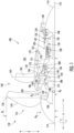
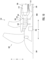
- FIG. 1 a schematic cross-sectional view of a gas turbine engine 100 is provided according to an example embodiment of the present disclosure.
- FIG. 1 provides a turbofan engine having a rotor assembly with a single stage of unducted rotor blades.
- the rotor assembly may be referred to herein as an "unducted fan,” or the entire engine 100 may be referred to as an "unducted turbofan engine.”
- the engine 100 of FIG. 1 includes a third stream extending from the compressor section to a rotor assembly flowpath over the turbomachine, as will be explained in more detail below.
- the engine 100 defines an axial direction A, a radial direction R, and a circumferential direction C. Moreover, the engine 100 defines an axial centerline or longitudinal axis 112 that extends along the axial direction A.
- the axial direction A extends parallel to the longitudinal axis 112
- the radial direction R extends outward from and inward to the longitudinal axis 112 in a direction orthogonal to the axial direction A
- the circumferential direction extends three hundred sixty degrees (360°) around the longitudinal axis 112.
- the engine 100 extends between a forward end 114 and an aft end 116, e.g., along the axial direction A.
- the engine 100 includes a turbomachine 120 and a rotor assembly, also referred to a fan section 150, positioned upstream thereof.
- the turbomachine 120 includes, in serial flow order, a compressor section, a combustion section, a turbine section, and an exhaust section.
- the turbomachine 120 includes a core cowl 122 that defines an annular core inlet 124.
- the core cowl 122 further encloses at least in part a low pressure system and a high pressure system.
- the core cowl 122 depicted encloses and supports at least in part a booster or low pressure (“LP") compressor 126 for pressurizing the air that enters the turbomachine 120 through core inlet 124.
- LP booster or low pressure
- a high pressure (“HP"), multi-stage, axial-flow compressor 128 receives pressurized air from the LP compressor 126 and further increases the pressure of the air.
- the pressurized air stream flows downstream to a combustor 130 of the combustion section where fuel is injected into the pressurized air stream and ignited to raise the temperature and energy level of the pressurized air.
- the high energy combustion products flow from the combustor 130 downstream to a high pressure turbine 132.
- the high pressure turbine 132 drives the high pressure compressor 128 through a high pressure shaft 136.
- the high pressure turbine 132 is drivingly coupled with the high pressure compressor 128.
- the high pressure compressor 128, the combustor 130, and the high pressure turbine 132 may collectively be referred to as the "core" of the engine 100.
- the high energy combustion products then flow to a low pressure turbine 134.
- the low pressure turbine 134 drives the low pressure compressor 126 and components of the fan section 150 through a low pressure shaft 138.
- the low pressure turbine 134 is drivingly coupled with the low pressure compressor 126 and components of the fan section 150.
- the LP shaft 138 is coaxial with the HP shaft 136 in this example embodiment.
- the turbomachine 120 defines a working gas flowpath or core duct 142 that extends between the core inlet 124 and the turbomachine exhaust nozzle 140.
- the core duct 142 is an annular duct positioned generally inward of the core cowl 122 along the radial direction R.
- the core duct 142 (e.g., the working gas flowpath through the turbomachine 120) may be referred to as a second stream.
- the fan section 150 includes a fan 152, which is the primary fan in this example embodiment.
- the fan 152 is an open rotor or unducted fan 152.
- the engine 100 may be referred to as an open rotor engine.
- the fan 152 includes an array of fan blades 154 (only one shown in FIG. 1 ).
- the fan blades 154 are rotatable, e.g., about the longitudinal axis 112.
- the fan 152 is drivingly coupled with the low pressure turbine 134 via the LP shaft 138.
- the fan 152 is coupled with the LP shaft 138 via a speed reduction gearbox 155, e.g., in an indirect-drive or geared-drive configuration.
- each fan blade 154 has a root and a tip and a span defined therebetween. Further, each fan blade 154 defines a fan blade tip radius R 1 along the radial direction R from the longitudinal axis 112 to the tip, and a hub radius (or inner radius) R 2 along the radial direction R from the longitudinal axis 112 to the base of each fan blade 154 (i.e., from the longitudinal axis 112 to a radial location where each fan blade 154 meets a front hub of the gas turbine engine 100 at a leading edge of the respective fan blade 154).
- a distance from the base of each fan blade 154 to a tip of the respective fan blade 154 is referred to as a span of the respective fan blade 154.
- the fan 152, or rather each fan blade 154 of the fan 152 defines a fan radius ratio, RqR, equal to R 1 divided by R 2 .
- the fan radius ratio, RqR, of the fan 152 may be referred to as the primary fan radius ratio, RqR Prim.-Fan .
- each fan blade 154 defines a central blade axis 156.
- each fan blade 154 of the fan 152 is rotatable about their respective central blade axis 156, e.g., in unison with one another.
- One or more actuators 158 are provided to facilitate such rotation and therefore may be used to change a pitch of the fan blades 154 about their respective central blades' axes 156.
- the fan section 150 further includes a fan guide vane array 160 that includes fan guide vanes 162 (only one shown in FIG. 1 ) disposed around the longitudinal axis 112.
- the fan guide vanes 162 are not rotatable about the longitudinal axis 112.
- Each fan guide vane 162 has a root and a tip and a span defined therebetween.
- the fan guide vanes 162 may be unshrouded as shown in FIG. 1 or, alternatively, may be shrouded, e.g., by an annular shroud spaced outward from the tips of the fan guide vanes 162 along the radial direction R or attached to the fan guide vanes 162.
- Each fan guide vane 162 defines a central blade axis 164.
- each fan guide vane 162 of the fan guide vane array 160 is rotatable about its respective central blade axis 164, e.g., in unison with one another.
- One or more actuators 166 are provided to facilitate such rotation and therefore may be used to change a pitch of the fan guide vane 162 about its respective central blade axis 164.
- each fan guide vane 162 may be fixed or unable to be pitched about its central blade axis 164.
- the fan guide vanes 162 are mounted to a fan cowl 170.
- a ducted fan 184 is included aft of the fan 152, such that the engine 100 includes both a ducted and an unducted fan which both serve to generate thrust through the movement of air without passage through at least a portion of the turbomachine 120 (e.g., without passage through the HP compressor 128 and combustion section for the embodiment depicted).
- the ducted fan 184 is rotatable about the same axis (e.g., the longitudinal axis 112) as the fan blade 154.
- the ducted fan 184 is, for the embodiment depicted, driven by the low pressure turbine 134 (e.g. coupled to the LP shaft 138).
- the fan 152 may be referred to as the primary fan, and the ducted fan 184 may be referred to as a secondary fan. It will be appreciated that these terms “primary” and “secondary” are terms of convenience, and do not imply any particular importance, power, or the like.
- the ducted fan 184 includes a plurality of fan blades (not separately labeled in FIG. 1 ; see fan blades 185 labeled in FIG. 2 ) arranged in a single stage, such that the ducted fan 184 may be referred to as a single stage fan.
- the fan blades of the ducted fan 184 can be arranged in equal spacing around the longitudinal axis 112.
- Each blade of the ducted fan 184 has a root and a tip and a span defined therebetween.
- each fan blade of the ducted fan 184 defines a fan blade tip radius R 3 along the radial direction R from the longitudinal axis 112 to the tip, and a hub radius (or inner radius) R 4 along the radial direction R from the longitudinal axis 112 to the base of the respective fan blades of the ducted fan 184 (i.e., a location where the respective fan blades of the ducted fan 184 meet an inner flowpath liner at a leading edge of the respective fan blades of the ducted fan 184).
- a distance from the base of each fan blade of the ducted fan 184 to a tip of the respective fan blade is referred to as a span of the respective fan blade.
- the ducted fan 184 or rather each fan blade of the ducted fan 184, defines a fan radius ratio, RqR, equal to R 3 divided by R 4 .
- the fan radius ratio, RqR, of the ducted fan 184 may be referred to as the secondary fan radius ratio, RqR sec-Fan .
- the fan cowl 170 annularly encases at least a portion of the core cowl 122 and is generally positioned outward of at least a portion of the core cowl 122 along the radial direction R. Particularly, a downstream section of the fan cowl 170 extends over a forward portion of the core cowl 122 to define a fan duct flowpath, or simply a fan duct 172. According to this embodiment, the fan flowpath or fan duct 172 may be understood as forming at least a portion of the third stream of the engine 100.
- Incoming air may enter through the fan duct 172 through a fan duct inlet 176 and may exit through a fan exhaust nozzle 178 to produce propulsive thrust.
- the fan duct 172 is an annular duct positioned generally outward of the core duct 142 along the radial direction R.
- the fan cowl 170 and the core cowl 122 are connected together and supported by a plurality of substantially radially-extending, circumferentially-spaced stationary struts 174 (only one shown in FIG. 1 ).
- the stationary struts 174 may each be aerodynamically contoured to direct air flowing thereby.
- Other struts in addition to the stationary struts 174 may be used to connect and support the fan cowl 170 and/or core cowl 122.
- the fan duct 172 and the core duct 142 may at least partially co-extend (generally axially) on opposite sides (e.g., opposite radial sides) of the core cowl 122.
- the fan duct 172 and the core duct 142 may each extend directly from a leading edge 144 of the core cowl 122 and may partially co-extend generally axially on opposite radial sides of the core cowl 122.
- the engine 100 also defines or includes an inlet duct 180.
- the inlet duct 180 extends between an engine inlet 182 and the core inlet 124/fan duct inlet 176.
- the engine inlet 182 is defined generally at the forward end of the fan cowl 170 and is positioned between the fan 152 and the fan guide vane array 160 along the axial direction A.
- the inlet duct 180 is an annular duct that is positioned inward of the fan cowl 170 along the radial direction R. Air flowing downstream along the inlet duct 180 is split, not necessarily evenly, into the core duct 142 and the fan duct 172 by a fan duct splitter or leading edge 144 of the core cowl 122.
- the inlet duct 180 is wider than the core duct 142 along the radial direction R.
- the inlet duct 180 is also wider than the fan duct 172 along the radial direction R.
- the secondary fan 184 is positioned at least partially in the inlet duct 180.
- the engine 100 includes one or more features to increase an efficiency of a third stream thrust, Fn 3S (e.g., a thrust generated by an airflow through the fan duct 172 exiting through the fan exhaust nozzle 178, generated at least in part by the ducted fan 184).
- Fn 3S a third stream thrust
- the engine 100 further includes an array of inlet guide vanes 186 positioned in the inlet duct 180 upstream of the ducted fan 184 and downstream of the engine inlet 182.
- the array of inlet guide vanes 186 are arranged around the longitudinal axis 112.
- the inlet guide vanes 186 are not rotatable about the longitudinal axis 112.
- Each inlet guide vanes 186 defines a central blade axis (not labeled for clarity), and is rotatable about its respective central blade axis, e.g., in unison with one another. In such a manner, the inlet guide vanes 186 may be considered a variable geometry component.
- One or more actuators 188 are provided to facilitate such rotation and therefore may be used to change a pitch of the inlet guide vanes 186 about their respective central blade axes.
- each inlet guide vanes 186 may be fixed or unable to be pitched about its central blade axis.
- the engine 100 located downstream of the ducted fan 184 and upstream of the fan duct inlet 176, the engine 100 includes an array of outlet guide vanes 190.
- the array of outlet guide vanes 190 are not rotatable about the longitudinal axis 112.
- the array of outlet guide vanes 190 are configured as fixed-pitch outlet guide vanes.
- the fan exhaust nozzle 178 of the fan duct 172 is further configured as a variable geometry exhaust nozzle.
- the engine 100 includes one or more actuators 192 for modulating the variable geometry exhaust nozzle.
- the variable geometry exhaust nozzle may be configured to vary a total cross-sectional area (e.g., an area of the nozzle in a plane perpendicular to the longitudinal axis 112) to modulate an amount of thrust generated based on one or more engine operating conditions (e.g., temperature, pressure, mass flowrate, etc. of an airflow through the fan duct 172).
- a fixed geometry exhaust nozzle may also be adopted.
- the combination of the array of inlet guide vanes 186 located upstream of the ducted fan 184, the array of outlet guide vanes 190 located downstream of the ducted fan 184, and the fan exhaust nozzle 178 may result in a more efficient generation of third stream thrust, Fn 3S , during one or more engine operating conditions. Further, by introducing a variability in the geometry of the inlet guide vanes 186 and the fan exhaust nozzle 178, the engine 100 may be capable of generating more efficient third stream thrust, Fn 3S , across a relatively wide array of engine operating conditions, including takeoff and climb (where a maximum total engine thrust Fn Total , is generally needed) as well as cruise (where a lesser amount of total engine thrust, Fn Total , is generally needed).
- air passing through the fan duct 172 may be relatively cooler (e.g., lower temperature) than one or more fluids utilized in the turbomachine 120.
- one or more heat exchangers 200 may be positioned in thermal communication with the fan duct 172.
- one or more heat exchangers 200 may be disposed within the fan duct 172 and utilized to cool one or more fluids from the core engine with the air passing through the fan duct 172, as a resource for removing heat from a fluid, e.g., compressor bleed air, oil or fuel.
- the heat exchanger 200 may be an annular heat exchanger extending substantially 360 degrees in the fan duct 172 (e.g., at least 300 degrees, such as at least 330 degrees). In such a manner, the heat exchanger 200 may effectively utilize the air passing through the fan duct 172 to cool one or more systems of the engine 100 (e.g., lubrication oil systems, compressor bleed air, electrical components, etc.).
- the heat exchanger 200 uses the air passing through duct 172 as a heat sink and correspondingly increases the temperature of the air downstream of the heat exchanger 200 and exiting the fan exhaust nozzle 178.
- the gas turbine engine 100 includes a primary fan, or rather fan 152 having fan blades 154, and a secondary fan, or rather ducted fan 184 having fan blades 185. Airflow from the fan 152 is split between a bypass passage 194 and the inlet duct 180 by an inlet splitter 196. Airflow from the ducted fan 184 is split between the fan duct 172 and the core duct 142 by the leading edge 144 (sometimes also referred to as a fan duct splitter).
- the exemplary gas turbine engine 100 depicted in FIG. 2 further defines a primary fan outer fan area, A P_Out , a primary fan inner fan area, A P_In , a secondary fan outer fan area, A S_Out , and a secondary fan inner fan area, A S_In .
- the primary fan outer fan area, A P_Out refers to an area defined by an annulus representing a portion of the fan 152 located outward of the inlet splitter 196 of the fan cowl 170.
- the gas turbine engine 100 further defines a fan cowl splitter radius, R 5 .
- the fan cowl splitter radius, R 5 is defined along the radial direction R from the longitudinal axis 112 to the inlet splitter 196.
- the primary fan outer fan area, A P_Out refers to an area defined by the formula: ⁇ R 1 2 ⁇ ⁇ R 5 2 .
- the primary fan inner fan area, A P_In refers to an area defined by an annulus representing a portion of the fan 152 located inward of the inlet splitter 196 of the fan cowl 170.
- the gas turbine engine 100 further defines an engine inlet inner radius, R 6 .
- the engine inlet inner radius, R 6 is defined along the radial direction R from the longitudinal axis 112 to an inner casing defining the engine inlet 182 directly inward along the radial direction R from the inlet splitter 196.
- the primary fan inner fan area, A P_In refers to an area defined by the formula: ⁇ R 5 2 ⁇ ⁇ R 6 2 .
- the secondary fan outer fan area, A S_Out refers to an area representing a portion of an airflow from the ducted fan 184 that is provided to the fan duct 172.
- the leading edge 144 defines a leading edge radius, R 7
- the gas turbine engine 100 defines an effective fan duct inlet outer radius, R 8 (see FIG. 3 ).
- the leading edge radius, R 7 is defined along the radial direction R from the longitudinal axis 112 to the leading edge 144.
- the fan duct 172 defines a cross-wise height 198 measured from the leading edge 144 to the fan cowl 170 in a direction perpendicular to a mean flow direction 204 of an airflow through a forward 10% of the fan duct 172.
- An angle 206 is defined by the mean flow direction 204 relative to a reference line 208 extending parallel to the longitudinal axis 112. The angle 206 is referred to as ⁇ . In certain embodiments, the angle 206 may be between 5 degrees and 80 degrees, such as between 10 degrees and 60 degrees (an increased angle is a counterclockwise rotation in FIG, 3 ).
- the effective fan duct inlet outer radius, R 8 is defined along the radial direction R from the longitudinal axis 112 to where the cross-wise height 198 meets the fan cowl 170.
- the secondary fan outer fan area, A S_Out refers to an area defined by the formula: ⁇ R 8 2 ⁇ R 7 2 cos ⁇ . .
- the secondary fan inner fan area, A S_In refers to an area defined by an annulus representing a portion of the ducted fan 184 located inward of the leading edge 144 of the core cowl 122.
- the gas turbine engine 100 further defines a core inlet inner radius, R 9 .
- the core inlet inner radius, R 9 is defined along the radial direction R from the longitudinal axis 112 to an inner casing defining the core inlet 124 directly inward along the radial direction R from the leading edge 144.
- the secondary fan inner fan area, A S_In refers to an area defined by the formula: ⁇ R 7 2 ⁇ ⁇ R 9 2 .
- the primary fan outer fan area, A P_Out , the primary fan inner fan area, A P_In , the secondary fan outer fan area, A S_Out , and the secondary fan inner fan area, A S_In may be used in defining various airflow ratios for the engine 100.
- the exemplary engine 100 of FIGS. 1 through 3 further defines a thrust to power airflow ratio and a core bypass ratio, which as discussed herein are used to define an engine in accordance with the present disclosure.
- the thrust to power airflow ratio is a ratio of an airflow through the bypass passage 194 of the engine 100 and through the fan duct 172 to an airflow through the core duct 142.
- the core bypass ratio is a ratio of an airflow through the fan duct 172 to the airflow through the core duct 142. These ratios are calculated while the engine 100 is operating at a rated speed during standard day operating conditions, and the amounts of airflow used to calculate these ratios are each expressed as a mass flowrate in the same units (mass per unit time).
- the amount of the airflow through the bypass passage 194 is determined using a fan pressure ratio for the fan 152 while operating at the rated speed during standard day operating conditions, and the primary fan outer fan area, A P_Out .
- the amount of airflow through the inlet duct 180 is determined using a fan pressure ratio for the fan 152 while operating at a rated speed during standard day operating conditions, and the primary fan inner fan area, A P_In .
- the amount of airflow through the fan duct 172 and the amount of airflow through the core duct 142 is determined based on the amount of airflow through the inlet duct 180 and the secondary fan outer fan area, A S_Out , and the secondary fan inner fan area, A S_In .
- gas turbine engine design i.e., designing gas turbine engines (e.g., both ducted and unducted turbofan engines and turboprop engines) having a variety of different primary fan and secondary fan characteristics - and evaluating an overall propulsive efficiency
- significant relationships exist in a ratio of an airflow through a bypass passage and through a third stream to an airflow through a core duct (referred to herein as a thrust to power airflow ratio), as well as in a ratio of an airflow through the third steam to the airflow through the core duct (referred to herein as a core bypass ratio).
- a fan diameter in order to provide a higher thrust to power airflow ratio, which typically correlates to a higher overall propulsive efficiency.
- increasing the fan diameter too much may actually result in a decrease in propulsive efficiency at higher speeds due to a drag from the fan blades.
- increasing the fan diameter too much may also create prohibitively heavy fan blades, creating installation problems due to the resulting forces on the supporting structure (e.g., frames, pylons, etc.), exacerbated by a need to space the engine having such fan blades further from a mounting location on the aircraft to allow the engine to fit, e.g., under/ over the wing, adjacent to the fuselage, etc.
- the fan duct may generally be desirable to increase an airflow through the fan duct relative to the core duct in order to provide a higher core bypass ratio, as such may also generally correlate to a higher overall propulsive efficiency.
- the higher the core bypass ratio the less airflow provided to the core of the gas turbine engine.
- a primary fan and a secondary fan of the gas turbine engine if less airflow is provided, either a maximum temperature of the core needs to be increased or a size of the primary fan or secondary fan needs to be decreased.
- Such a result can lead to either premature wear of the core or a reduction in propulsive efficiency of the gas turbine engine.
- the inventors of the present disclosure discovered bounding the relationships defined by the thrust to power airflow ratio and core bypass ratio can result in a gas turbine engine maintaining or even improving upon a desired propulsive efficiency, while also taking into account the gas turbine engine's packaging concerns and weight concerns, and also providing desired thermal management capabilities.
- the relationship discovered, infra can identify an improved engine configuration suited for a particular mission requirement, one that takes into account installation, packaging and loading, thermal sink needs and other factors influencing the optimal choice for an engine configuration.
- TPAR A B + A 3 S / A C
- CBR A 3 S / A C
- TPAR a thrust to power airflow ratio
- CBR a core bypass ratio
- a B is an airflow through a bypass passage of the gas turbine engine while the engine is operated at a rated speed during standard day operating conditions
- Ass is an airflow through a third stream of the gas turbine engine while the engine is operated at the rated speed during standard day operating conditions
- Ac is an airflow through a core of the gas turbine engine while the engine is operated at the rated speed during standard day operating conditions.
- the airflow through the core of the gas turbine engine may refer to an airflow through an upstream end of the core (e.g., an airflow through a first stage of a high pressure compressor of the core).
- a B , A 3S , and Ac are each expressed as mass flowrate, with the same units as one another.
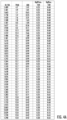
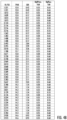
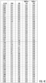
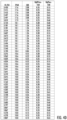
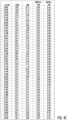
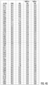
- FIGS. 4A through 4H and 5A through 5D the relationships between the various parameters of Expressions (1) and (2) of exemplary gas turbine engines are illustrated in accordance with one or more exemplary embodiments of the present disclosure.
- FIGS. 4A through 4H provide a table including numerical values corresponding to several of the plotted gas turbine engines in FIGS. 5A through 5D.
- FIGS. 5A through 5D are plots of gas turbine engines in accordance with one or more exemplary embodiments of the present disclosure, showing the TPAR (Y-Axis) and the CBR (X-axis).
- FIGS. 5A through 5D highlight preferred subranges, including subranges for unducted engines, ducted engines, and turboprop engines, as discussed hereinbelow.
- a first range 402 and a second range 404 are provided, and exemplary embodiments 406 are plotted.
- the exemplary embodiments 406 include a variety of gas turbine engine types in accordance with aspects of the present disclosure, including unducted turbofan engines, ducted turbofan engines, and turboprop engines.
- the first range 402 corresponds to a TPAR between 3.5 and 100 and a CBR between 0.1 and 10.
- the first range 402 captures the benefits of the present disclosure across the variety of engine types.
- the second range 404 corresponds to a TPAR between 14 and 75 and a CBR between 0.3 and 5.
- the second range 404 may provide more desirable TPAR and CBR relationships across the variety of engine types to achieve propulsive efficiency, while still providing packaging and weight benefits, thermal benefits, etc.
- a third range 408 and a fourth range 410 are provided, and exemplary embodiments 412 are plotted.
- the exemplary embodiments 412 include a variety of unducted gas turbine engines in accordance with aspects of the present disclosure.
- the exemplary embodiments 412 include a variety of gas turbine engines having an unducted primary fan, similar to the exemplary embodiments described herein with reference to FIGS. 1 and 10 .
- the third range 408 corresponds to a TPAR between 30 and 56 and a CBR between 0.3 and 5.
- the third range 408 captures the benefits of the present disclosure for unducted gas turbine engines.
- the fourth range 410 corresponds to a TPAR between 35 and 50 and a CBR between 0.5 and 3.
- the fourth range 410 may provide more desirable TPAR and CBR relationships for the unducted gas turbine engines to achieve propulsive efficiency, while still providing packaging and weight benefits, thermal benefits, etc.
- the unducted gas turbine engines may have, on the whole, a higher TPAR as compared to the ducted gas turbine engines (see FIG. 5C ), enabled by a lack of an outer nacelle or other casing surrounding a primary fan.
- the range of CBR values in the fourth range 410 isn't as large as the range of CBR values in the third range 408, as in the embodiments with a higher TPAR, the CBR needs to be lower to provide a necessary amount of airflow to a core of the engine without exceeding temperature thresholds or requiring an undesired reduction in a size of the primary fan.
- TPAR values and CBR values in the third and fourth ranges 408, 410 shown may provide a desirable propulsive benefit, while still enabling operation of the core in a reasonable manner, and balancing installation and thermal load considerations.
- a fifth range 414, a sixth range 416, a seventh range 417, an eighth range 418, a ninth range 419, and a tenth range 420 are provided, and exemplary embodiments 421 are plotted.
- the exemplary embodiments 421 include a variety of ducted gas turbine engines in accordance with aspects of the present disclosure.
- the exemplary embodiments 421 include a variety of gas turbine engines having a ducted primary fan, similar to the exemplary embodiments described herein with reference to FIGS. 7 through 9 .
- the fifth range 414 corresponds to a TPAR between 3.5 and 40 and a CBR between 0.3 and 5.
- the fifth range 414 captures the benefits of the present disclosure for ducted gas turbine engines.
- the sixth range 416 corresponds to a TPAR between 3.5 and 20 and a CBR between 0.2 and 5.
- the sixth range 416 captures the benefits of the present disclosure for ducted gas turbine engines in a direct drive configuration (see, e.g., FIG. 7 ).
- a primary fan may be smaller, limiting a TPAR.
- the seventh range 417 which also corresponds to ducted gas turbine engines in a direct drive configuration, corresponds to a TPAR between 6 and 15 and a CBR between 0.3 and 1.8, and may represent a more preferrable range.
- the eighth range 418 corresponds to a TPAR between 8 and 40 and a CBR between 0.2 and 5.
- the eighth range 418 captures the benefits of the present disclosure for ducted gas turbine engines in a geared configuration (see, e.g., FIGS. 8 and 9 ).
- a primary fan may be larger as compared to a ducted, direct drive gas turbine engine, allowing for a larger TPAR.
- TPAR is, in turn limited by an allowable nacelle drag and fan operability.
- the ninth range 419 corresponds to ducted gas turbine engines in a geared configuration having a variable pitch primary fan (see FIGS. 8 and 9 ) and the tenth range 420 corresponds to ducted gas turbine engines in a geared configuration having a fixed pitch primary fan. Inclusion of a variable pitch primary fan may allow for a larger fan, but may also necessitate higher heat rejection abilities for the gas turbine engine, which may, in turn increase a CBR.
- the ninth range 419 corresponds to a TPAR between 20 and 35 and a CBR between 0.5 and 3
- the tenth range 420 corresponds to a TPAR between 10 and 20 and a CBR between 0.3 and 2.
- a gas turbine engine of the present disclosure in a ducted, geared, variable pitch configuration may have TPAR between 15 and 40 and a CBR between 0.3 and 5
- a gas turbine engine in a ducted, geared, fixed pitch configuration may have TPAR between 8 and 25 and a CBR between 0.3 and 5.
- the ducted gas turbine engines may have, on the whole, a lower TPAR than the unducted gas turbine engines as a result of an outer nacelle surrounding a primary fan (the outer nacelle becoming prohibitively heavy with higher diameter primary fans).
- the TPAR values for geared engines may be higher than the TPAR values for direct drive engines, as inclusion of the gearbox allows the primary fan to rotate more slowly than the driving turbine, enabling a comparatively larger primary fan without overloading the primary fan or generating shock losses at a tip of the primary fan.
- the range of CBR values may generally be relatively high given the relatively low TPAR values (since a relatively high amount of airflow is provided to a secondary fan through an engine inlet when the TPAR values are low), as a necessary amount of airflow to a core of the ducted gas turbine engine may still be provided with a relatively high CBR without exceeding temperature thresholds or requiring a reduction in a size of the primary fan.
- TPAR values and CBR values in the fifth, sixth, seventh, eighth, ninth, and tenth ranges 414, 416, 417, 418, 419, 420 shown may provide a desirable propulsive benefit, while still enabling operation of the core in a reasonable manner, and balancing installation and thermal load considerations.
- an eleventh range 422 and a twelfth range 423 are provided, and exemplary embodiments 424 are plotted.
- the exemplary embodiments 424 include a variety of turboprop gas turbine engines in accordance with aspects of the present disclosure.
- the exemplary embodiments 424 include a variety of turboprop gas turbine engine similar to the exemplary embodiment described herein with reference to FIG. 6 .
- the eleventh range 422 corresponds to a TPAR between 40 and 100 and a CBR between 0.3 and 5.
- the eleventh range 422 captures the benefits of the present disclosure for turboprop gas turbine engines.
- the twelfth range 423 corresponds to a TPAR between 50 and 70 and a CBR between 0.5 and 3, and may represent a more preferrable range.
- turboprop gas turbine engines may have, on the whole, higher TPAR values than turbofan engines, enabled by the lack of an outer nacelle or other casing surrounding a primary fan and a relatively slow operational speed of the primary fan and aircraft incorporating the turboprop gas turbine engine.
- the range of CBR values in the eleventh range 422 and the twelfth range 423 may be relatively small, as less air may be provided through a third stream with such a high TPAR without compromising operation of a core of the gas turbine engine.
- TPAR values and CBR values in the eleventh range 422 and twelfth range 423 shown may provide a desirable propulsive benefit, while still enabling operation of the core in a reasonable manner, and balancing installation and thermal load considerations.
- the term “Ducted” refers to inclusion of an outer nacelle around a primary fan (see, e.g., FIGS. 7 to 9 ); "Open Rotor” refers to inclusion of an unducted primary fan (see, e.g., FIGS. 1 , 10 ); “Geared” refers to inclusion of a reduction gearbox between the primary fan and a driving turbine (see, e.g., FIGS. 8 to 10 ); “Direct Drive” refers to exclusion of a reduction gearbox between the primary fan and a driving turbine (see, e.g., FIG.
- Variable Pitch refers to inclusion of a pitch change mechanism for changing a pitch of fan blades on a primary fan (see, e.g., FIGS. 1 , 8, 9 );
- Fixed Pitch refers to exclusion of a pitch change mechanism for changing a pitch of fan blades on a primary fan (see, e.g., FIGS. 6 to 7 );
- low flight speed refers to an engine designed to operate at a flight speed less than 0.85 Mach; and “higher flight speed” refers to an engine designed to operate at a flight speed higher than 0.85 Mach.
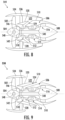
- Each of the gas turbine engines of FIGS. 6 through 9 generally include a rotor 502 rotatable about a rotor axis 504 and a turbomachine 506 rotatable about a longitudinal axis 508.
- the rotor 502 corresponds to the "primary fan” described herein.
- the turbomachine 506 is surrounded at least in part by a core cowl 510 and includes a compressor section 512, a combustion section 514, and a turbine section 516 in serial flow order.
- the gas turbine engines of FIGS. 7 through 9 each also include a ducted mid-fan or secondary fan 518.
- the gas turbine engines each include a fan cowl 520 surrounding the secondary fan 518.
- the gas turbine engines each also define a bypass passage 522 downstream of the respective rotor 502 and over the respective fan cowl 520 and core cowl 510, and further define a third stream 524 extending from a location downstream of the respective secondary fan 518 to the respective bypass passage 522 (at least in the embodiments depicted; in other embodiments, the third stream 524 may instead extend to a location downstream of the bypass passage 522).
- the exemplary gas turbine engine depicted is configured as a turboprop engine 526.
- the rotor 502 (or primary fan) is configured as a propeller, defining a relatively large diameter.
- the turboprop engine 526 includes an engine shaft 528 driven by the turbomachine 506, a fan shaft 530 rotatable with the rotor 502, and a gearbox 532 mechanically coupling the engine shaft 528 with the fan shaft 530.
- the gearbox 532 is an offset gearbox such that the rotor axis 504 is radially offset from the longitudinal axis 508 of the turboprop engine 526.
- a turboprop engine may be provided with a reverse flow combustor.
- the gas turbine engines are each configured as turbofan engines, and more specifically as ducted turbofan engines.
- the gas turbine engines each include an outer nacelle 534 surrounding the rotor 502, and the rotor 502 (or primary fan) of each is therefore configured as a ducted fan.
- each of the gas turbine engines includes outlet guide vanes 536 extending through the bypass passage 522 to the outer nacelle 534 from the fan cowl 520, the core cowl 510, or both.
- the gas turbine engine of FIG. 7 is configured as a direct drive, ducted, turbofan engine 538.
- the direct drive, ducted, turbofan engine 538 includes an engine shaft 540 driven by the turbine section 516 and a fan shaft 542 rotatable with the rotor 502.
- the fan shaft 542 is configured to rotate directly with (i.e., at the same speed as) the engine shaft 540.
- the gas turbine engine of FIG. 8 is configured as a geared, ducted, turbofan engine 544.
- the geared, ducted, turbofan engine 544 includes the engine shaft 540 driven by the turbine section 516 and the fan shaft 542 rotatable with the rotor 502.
- the exemplary geared, ducted, turbofan engine 544 further includes a gearbox 546 mechanically coupling the engine shaft 540 to the fan shaft 542. The gearbox 546 allows the rotor 502 to rotate at a slower speed than the engine shaft 540, and thus at a slower speed than the secondary fan 518.
- the exemplary geared, ducted, turbofan engine 544 of FIG. 8 further includes a pitch change mechanism 548 operable with the rotor 502 to change a pitch of the rotor blades of the rotor 502. Such may allow for an increased efficiency of the gas turbine engine.
- the exemplary gas turbine engine of FIG. 9 is again configured as a direct drive, ducted, turbofan engine 538.
- the fan duct outlet defined by the fan duct is downstream of the bypass passage outlet defined by the bypass passage.
- FIG. 10 a gas turbine engine in accordance with yet another exemplary embodiment of the present disclosure is provided.
- the exemplary gas turbine engine of FIG. 10 may be configured in a similar manner as the exemplary gas turbine engines described above with reference to FIG. 7 and 8 .
- the exemplary gas turbine engine of FIG. 10 includes a rotor 502 rotatable about a rotor axis 504 and a turbomachine 506 rotatable about a longitudinal axis 508.
- the rotor axis 504 and the longitudinal axis 508 are aligned in the embodiment of FIG. 10 .
- the rotor 502 corresponds to the "primary fan" described herein.
- the turbomachine 506 is surrounded at least in part by a core cowl 510 and includes a compressor section 512 (and, not shown, a combustion section and a turbine section in serial flow order with the compressor section 512).
- the gas turbine engine also includes a ducted mid-fan or secondary fan 518 and a fan cowl 520 surrounding the secondary fan 518.
- the gas turbine engine is configured as an unducted turbofan engine 550 (see, e.g., FIG. 1 ), and the secondary fan 518 is not configured as a single stage fan (see fan 184 of FIG. 1 ).
- the secondary fan 518 is configured as a multi-stage secondary fan, and more specifically still as a two-stage secondary fan having a total of two stages of rotating compressor rotor blades, and more specifically having a first stage 552 of secondary fan rotor blades and a second stage 554 of secondary fan rotor blades.
- the turbomachine 506 does not include a separate low pressure compressor.
- a method of operating a gas turbine engine is provided.
- the method may be utilized with one or more of the exemplary gas turbine engines discussed herein, such as in FIGS. 1 through 10 .
- the method includes operating the gas turbine engine at a rated speed, wherein operating the gas turbine engine at the rated speed comprises operating the gas turbine engine to define a thrust to power airflow ratio between 3.5 and 100 and a core bypass ratio between 0.1 and 5.
- the thrust to power airflow ratio is a ratio of an airflow through a bypass passage over a turbomachine of the gas turbine engine plus an airflow through a fan duct to an airflow through a core duct
- the core bypass ratio is a ratio of the airflow through the fan duct to the airflow through the core duct.
- FIGS. 1 and 2 various embodiments of a gas turbine engine are provided. Certain of these embodiments may be an unducted, single rotor gas turbine engine (see FIGS. 1 and 2 ), a turboprop engine (see FIG. 6 ), or a ducted turbofan engine (see FIGS. 7 through 9 ).
- FIGS. 7 through 9 Another example of a ducted turbofan engine can be found in U.S. Patent Application No. 16/811,368 (Published as U.S. Patent Application Publication No. 2021/0108597), filed March 6, 2020 ( FIG.
- the engine may include a heat exchanger located in an annular duct, such as in a third stream.
- the heat exchanger may extend substantially continuously in a circumferential direction of the gas turbine engine (e.g., at least 300 degrees, such as at least 330 degrees).
- a threshold power or disk loading for a fan may range from 25 horsepower per square foot (hp/ft 2 ) or greater at cruise altitude during a cruise operating mode.
- structures and methods provided herein generate power loading between 80 hp/ft 2 and 160 hp/ ft 2 or higher at cruise altitude during a cruise operating mode, depending on whether the engine is an open rotor or ducted engine.
- an engine of the present disclosure is applied to a vehicle with a cruise altitude up to approximately 65,000 ft.
- cruise altitude is between approximately 28,000 ft and approximately 45,000 ft.
- cruise altitude is expressed in flight levels based on a standard air pressure at sea level, in which a cruise flight condition is between FL280 and FL650.
- cruise flight condition is between FL280 and FL450.
- cruise altitude is defined based at least on a barometric pressure, in which cruise altitude is between approximately 4.85 psia and approximately 0.82 psia based on a sea level pressure of approximately 14.70 psia and sea level temperature at approximately 59 degrees Fahrenheit.
- cruise altitude is between approximately 4.85 psia and approximately 2.14 psia. It should be appreciated that in certain embodiments, the ranges of cruise altitude defined by pressure may be adjusted based on a different reference sea level pressure and/or sea level temperature.
- an engine of such a configuration may be configured to generate at least 25,000 pounds and less than 80,000 of thrust during operation at a rated speed, such as between 25,000 and 50,000 pounds of thrust during operation at a rated speed, such as between 25,000 and 40,000 pounds of thrust during operation at a rated speed.
- an engine of the present disclosure may be configured to generate much less power, such as at least 2,000 pounds of thrust during operation at a rated speed.
- the fan may include twelve (12) fan blades. From a loading standpoint, such a blade count may allow a span of each blade to be reduced such that the overall diameter of the primary fan may also be reduced (e.g., to twelve feet in one exemplary embodiment). That said, in other embodiments, the fan may have any suitable blade count and any suitable diameter. In certain suitable embodiments, the fan includes at least eight (8) blades. In another suitable embodiment, the fan may have at least twelve (12) blades. In yet another suitable embodiment, the fan may have at least fifteen (15) blades. In yet another suitable embodiment, the fan may have at least eighteen (18) blades.
- the fan includes twenty-six (26) or fewer blades , such as twenty (20) or fewer blades.
- the fan may only include at least four (4) blades, such as with a fan of a turboprop engine.
- the rotor assembly may define a rotor diameter (or fan diameter) of at least 10 feet, such as at least 11 feet, such as at least 12 feet, such as at least 13 feet, such as at least 15 feet, such as at least 17 feet, such as up to 28 feet, such as up to 26 feet, such as up to 24 feet, such as up to 18 feet.
- the engine includes a ratio of a quantity of vanes to a quantity of blades that could be less than, equal to, or greater than 1:1.
- the engine includes twelve (12) fan blades and ten (10) vanes.
- the vane assembly includes a greater quantity of vanes to fan blades.
- the engine includes ten (10) fan blades and twenty-three (23) vanes.
- the engine may include a ratio of a quantity of vanes to a quantity of blades between 1:2 and 5:2. The ratio may be tuned based on a variety of factors including a size of the vanes to ensure a desired amount of swirl is removed for an airflow from the primary fan.
- a ratio R1/R2 may be between 1 and 10, or 2 and 7, or at least 3.3, at least 3.5, at least 4 and less than or equal to 7, where R1 is the radius of the primary fan and R2 is the radius of the mid-fan.
- the engine may allow for normal subsonic aircraft cruise altitude operation at or above Mach 0.5.
- the engine allows for normal aircraft operation between Mach 0.55 and Mach 0.85 at cruise altitude.
- the engine allows for normal aircraft operation between Mach 0.75 and Mach 0.85.
- the engine allows for rotor blade tip speeds at or less than 750 feet per second (fps).
- the rotor blade tip speed at a cruise flight condition can be 650 to 900 fps, or 700 to 800 fps.
- the engine allows for normal aircraft operation of at least Mach 0.3, such as with turboprop engines.
- a fan pressure ratio (FPR) for the primary fan of the fan assembly can be 1.04 to 2.20, or in some embodiments 1.05 to 1.2, or in some embodiments less than 1.08, as measured across the fan blades of the primary fan at a cruise flight condition.
- a gear assembly may be provided to reduce a rotational speed of the fan assembly relative to a driving shaft (such as a low pressure shaft coupled to a low pressure turbine).
- a gear ratio of the input rotational speed to the output rotational speed is between 3.0 and 4.0, between 3.2 and 3.5, or between 3.5 and 4.5.
- a gear ratio of the input rotational speed to the output rotational speed is greater than 4.1.
- the gear ratio is within a range of 4.1 to 14.0, within a range of 4.5 to 14.0, or within a range of 6.0 to 14.0.
- the gear ratio is within a range of 4.5 to 12 or within a range of 6.0 to 11.0.
- the compressors and/or turbines can include various stage counts.
- the stage count includes the number of rotors or blade stages in a particular component (e.g., a compressor or turbine).
- a low pressure compressor may include 1 to 8 stages
- a high-pressure compressor may include 4 to 15 stages
- a high-pressure turbine may include 1 to 2 stages
- a low pressure turbine may include 1 to 7 stages.
- the LPT may have 4 stages, or between 4 and 7 stages.
- an engine may include a one stage low pressure compressor, an 11 stage high pressure compressor, a two stage high pressure turbine, and 4 stages, or between 4 and 7 stages for the LPT.
- an engine can include a three stage low-pressure compressor, a 10 stage high pressure compressor, a two stage high pressure turbine, and a 7 stage low pressure turbine.
- a core engine is generally encased in an outer casing defining one half of a core diameter (Dcore), which may be thought of as the maximum extent from a centerline axis (datum for R).
- the engine includes a length (L) from a longitudinally (or axial) forward end to a longitudinally aft end.
- the engine defines a ratio of L/Dcore that provides for reduced installed drag.
- L/Dcore is at least 2.
- L/Dcore is at least 2.5.
- the L/Dcore is less than 5, less than 4, and less than 3.
- the L/Dcore is for a single unducted rotor engine.
- the reduced installed drag may further provide for improved efficiency, such as improved specific fuel consumption. Additionally, or alternatively, the reduced installed drag may provide for cruise altitude engine and aircraft operation at the above describe Mach numbers at cruise altitude. Still particular embodiments may provide such benefits with reduced interaction noise between the blade assembly and the vane assembly and/or decreased overall noise generated by the engine by virtue of structures located in an annular duct of the engine.
- ranges of power loading and/or rotor blade tip speed may correspond to certain structures, core sizes, thrust outputs, etc., or other structures of the core engine.
- the present disclosure may include combinations of structures not previously known to combine, at least for reasons based in part on conflicting benefits versus losses, desired modes of operation, or other forms of teaching away in the art.
- certain aspects of the disclosure may address issues that may be particular to unshrouded or open rotor engines, such as, but not limited to, issues related to gear ratios, fan diameter, fan speed, length (L) of the engine, maximum diameter of the core engine (Dcore) of the engine, L/Dcore of the engine, desired cruise altitude, and/or desired operating cruise speed, or combinations thereof.
- a gas turbine engine comprising: a turbomachine comprising a compressor section, a combustion section, and a turbine section arranged in serial flow order, the turbomachine defining an engine inlet to an inlet duct, a fan duct inlet to a fan duct, and a core inlet to a core duct; a primary fan driven by the turbomachine; and a secondary fan located downstream of the primary fan within the inlet duct, the gas turbine engine defining a thrust to power airflow ratio between 3.5 and 100 and a core bypass ratio between 0.1 and 10, wherein the thrust to power airflow ratio is a ratio of an airflow through a bypass passage over the turbomachine plus an airflow through the fan duct to an airflow through the core duct, and wherein the core bypass ratio is a ratio of the airflow through the fan duct to the airflow through the core duct.
- the gas turbine engine of any preceding clause wherein the primary fan is an unducted primary fan, and wherein the thrust to power airflow ratio between 30 and 60.
- gas turbine engine of any preceding clause, wherein the gas turbine engine is a turboprop engine, and wherein the thrust to power airflow ratio between 40 and 100.
- gas turbine engine of any preceding clause, wherein the gas turbine engine is a direct drive gas turbine engine, and wherein the thrust to power airflow ratio is between 3.5 and 20.
- gas turbine engine of any preceding clause, wherein the gas turbine engine is a geared gas turbine engine, and wherein the thrust to power airflow ratio is between 8 and 40.
- the primary fan is a ducted primary fan comprising an outer nacelle surrounding the primary fan and defining the bypass passage downstream of the primary fan and over the turbomachine, wherein the gas turbine engine further defines a bypass passage outlet at a downstream end of the outer nacelle, wherein the fan duct defines a fan duct outlet, and wherein the fan duct outlet is downstream of the bypass passage outlet.
- the primary fan is a ducted primary fan comprising an outer nacelle surrounding the primary fan and defining the bypass passage downstream of the primary fan and over the turbomachine, wherein the gas turbine engine further defines a bypass passage outlet at a downstream end of the outer nacelle, wherein the fan duct defines a fan duct outlet, and wherein the fan duct outlet is upstream of the bypass passage outlet.
- a method of operating a gas turbine engine comprising: operating the gas turbine engine at a rated speed, wherein operating the gas turbine engine at the rated speed comprises operating the gas turbine engine to define a thrust to power airflow ratio between 3.5 and 100 and a core bypass ratio between 0.1 and 5, wherein the thrust to power airflow ratio is a ratio of an airflow through a bypass passage over a turbomachine of the gas turbine engine plus an airflow through a fan duct to an airflow through a core duct, and wherein the core bypass ratio is a ratio of the airflow through the fan duct to the airflow through the core duct.
- the primary fan is an unducted primary fan, and wherein the thrust to power airflow ratio between 30 and 60.
Landscapes
- Engineering & Computer Science (AREA)
- Chemical & Material Sciences (AREA)
- Combustion & Propulsion (AREA)
- Mechanical Engineering (AREA)
- General Engineering & Computer Science (AREA)
- Structures Of Non-Positive Displacement Pumps (AREA)
Applications Claiming Priority (1)
| Application Number | Priority Date | Filing Date | Title |
|---|---|---|---|
| US17/879,384 US12031504B2 (en) | 2022-08-02 | 2022-08-02 | Gas turbine engine with third stream |
Publications (1)
| Publication Number | Publication Date |
|---|---|
| EP4317659A1 true EP4317659A1 (fr) | 2024-02-07 |
Family
ID=87158425
Family Applications (1)
| Application Number | Title | Priority Date | Filing Date |
|---|---|---|---|
| EP23183581.0A Pending EP4317659A1 (fr) | 2022-08-02 | 2023-07-05 | Moteur à turbine à gaz avec troisième flux |
Country Status (2)
| Country | Link |
|---|---|
| US (2) | US12031504B2 (fr) |
| EP (1) | EP4317659A1 (fr) |
Families Citing this family (4)
| Publication number | Priority date | Publication date | Assignee | Title |
|---|---|---|---|---|
| US12584455B2 (en) * | 2022-08-02 | 2026-03-24 | General Electric Company | Airflow mixer assembly for a gas turbine engine |
| US12031504B2 (en) | 2022-08-02 | 2024-07-09 | General Electric Company | Gas turbine engine with third stream |
| WO2025199328A1 (fr) * | 2024-03-21 | 2025-09-25 | General Electric Company | Ensemble mélangeur de flux d'air pour moteur à turbine à gaz |
| WO2025259893A1 (fr) * | 2024-06-12 | 2025-12-18 | General Electric Company | Moteur à turbine à gaz doté d'un troisième flux |
Citations (2)
| Publication number | Priority date | Publication date | Assignee | Title |
|---|---|---|---|---|
| US20210108597A1 (en) | 2019-10-15 | 2021-04-15 | General Electric Company | Propulsion system architecture |
| US20220042463A1 (en) * | 2020-08-04 | 2022-02-10 | Ge Avio S.R.L. | Gearbox efficiency rating for turbomachine engines |
Family Cites Families (141)
| Publication number | Priority date | Publication date | Assignee | Title |
|---|---|---|---|---|
| US2999630A (en) | 1957-08-08 | 1961-09-12 | Gen Electric | Compressor |
| DE1081277B (de) | 1958-08-16 | 1960-05-05 | Johann Endres Dr Ing | Zweistrombrennkammer fuer Gasturbinen, insbesondere Gasturbinen-Strahltriebwerke |
| US3750402A (en) | 1963-08-07 | 1973-08-07 | Gen Electric | Mixed flow augmentation system |
| US3540682A (en) | 1964-12-02 | 1970-11-17 | Gen Electric | Turbofan type engine frame and support system |
| US3542152A (en) | 1968-04-08 | 1970-11-24 | Gen Electric | Sound suppression panel |
| US3528250A (en) | 1969-04-16 | 1970-09-15 | Gen Motors Corp | Bypass engine with afterburning and compressor bleed air heat exchanger in bypass duct |
| US4043121A (en) | 1975-01-02 | 1977-08-23 | General Electric Company | Two-spool variable cycle engine |
| US4010608A (en) | 1975-06-16 | 1977-03-08 | General Electric Company | Split fan work gas turbine engine |
| US4163366A (en) | 1977-05-23 | 1979-08-07 | Avco Corporation | Apparatus for disposal of leaking fluids in a turbofan engine |
| US4486146A (en) | 1980-08-08 | 1984-12-04 | British Aerospace Public Limited Company | Aircraft propulsion means |
| US4446696A (en) | 1981-06-29 | 1984-05-08 | General Electric Company | Compound propulsor |
| US4569199A (en) | 1982-09-29 | 1986-02-11 | The Boeing Company | Turboprop engine and method of operating the same |
| US4607657A (en) | 1985-10-28 | 1986-08-26 | General Electric Company | Aircraft engine inlet |
| US4860537A (en) | 1986-08-29 | 1989-08-29 | Brandt, Inc. | High bypass ratio counterrotating gearless front fan engine |
| GB2196390B (en) | 1986-10-16 | 1991-06-26 | Rolls Royce Plc | Intake for turbopropeller gas turbine engine. |
| US4784575A (en) | 1986-11-19 | 1988-11-15 | General Electric Company | Counterrotating aircraft propulsor blades |
| US4892269A (en) | 1988-04-28 | 1990-01-09 | Allied-Signal Inc. | Spinner ducted exhaust for pusher turboprop engines |
| US4976102A (en) | 1988-05-09 | 1990-12-11 | General Electric Company | Unducted, counterrotating gearless front fan engine |
| US4907946A (en) | 1988-08-10 | 1990-03-13 | General Electric Company | Resiliently mounted outlet guide vane |
| US5054998A (en) | 1988-09-30 | 1991-10-08 | The Boeing Company, Inc. | Thrust reversing system for counter rotating propellers |
| US4916894A (en) | 1989-01-03 | 1990-04-17 | General Electric Company | High bypass turbofan engine having a partially geared fan drive turbine |
| US4941803A (en) | 1989-02-01 | 1990-07-17 | United Technologies Corporation | Airfoiled blade |
| JPH0370698A (ja) | 1989-08-11 | 1991-03-26 | Naomasa Nomura | 頭部回転式高性能飛行機 |
| US5190441A (en) | 1990-08-13 | 1993-03-02 | General Electric Company | Noise reduction in aircraft propellers |
| US5197855A (en) | 1991-07-01 | 1993-03-30 | United Technologies Corporation | Engine exhaust/blade interaction noise suppression |
| US5457346A (en) | 1992-02-10 | 1995-10-10 | Blumberg; Stanley | Windmill accelerator |
| US5261227A (en) | 1992-11-24 | 1993-11-16 | General Electric Company | Variable specific thrust turbofan engine |
| US5345760A (en) | 1993-02-05 | 1994-09-13 | General Electric Company | Turboprop booster |
| US5259187A (en) | 1993-02-05 | 1993-11-09 | General Electric Company | Method of operating an aircraft bypass turbofan engine having variable fan outlet guide vanes |
| US5562404A (en) | 1994-12-23 | 1996-10-08 | United Technologies Corporation | Vaned passage hub treatment for cantilever stator vanes |
| US6082670A (en) | 1997-06-26 | 2000-07-04 | Electric Boat Corporation | Method and arrangement for fluidborne vehicle propulsion and drag reduction |
| CN1204005A (zh) | 1997-06-26 | 1999-01-06 | 亚瑞亚·勃朗勃威力有限公司 | 喷气式发动机 |
| USH2032H1 (en) | 1999-10-01 | 2002-07-02 | The United States Of America As Represented By The Secretary Of The Air Force | Integrated fan-core twin spool counter-rotating turbofan gas turbine engine |
| US6547518B1 (en) | 2001-04-06 | 2003-04-15 | General Electric Company | Low hoop stress turbine frame support |
| US6763654B2 (en) | 2002-09-30 | 2004-07-20 | General Electric Co. | Aircraft gas turbine engine having variable torque split counter rotating low pressure turbines and booster aft of counter rotating fans |
| DE60210512T2 (de) | 2002-10-11 | 2006-11-23 | Unzicker, Stefan, Dipl.-Ing. | Senkrecht startendes und landendes flugzeug |
| US6792758B2 (en) | 2002-11-07 | 2004-09-21 | Siemens Westinghouse Power Corporation | Variable exhaust struts shields |
| US7234914B2 (en) | 2002-11-12 | 2007-06-26 | Continum Dynamics, Inc. | Apparatus and method for enhancing lift produced by an airfoil |
| GB2401654B (en) | 2003-05-14 | 2006-04-19 | Rolls Royce Plc | A stator vane assembly for a turbomachine |
| US6905303B2 (en) | 2003-06-30 | 2005-06-14 | General Electric Company | Methods and apparatus for assembling gas turbine engines |
| US7216475B2 (en) | 2003-11-21 | 2007-05-15 | General Electric Company | Aft FLADE engine |
| GB0406174D0 (en) | 2004-03-19 | 2004-04-21 | Rolls Royce Plc | Turbine engine arrangement |
| CA2467199A1 (fr) | 2004-05-19 | 2005-11-19 | Bud T.J. Johnson | Eolienne |
| WO2007001372A2 (fr) | 2004-09-17 | 2007-01-04 | Aurora Flight Sciences | Casserole carenee de refroidissement du reacteur |
| JP2006123880A (ja) | 2004-10-29 | 2006-05-18 | Masahiko Senda | ダクテッドファンを推進力に飛行する飛行物体を安定させる構造 |
| US7658063B1 (en) | 2005-07-15 | 2010-02-09 | Florida Turbine Technologies, Inc. | Gas turbine having a single shaft bypass configuration |
| FR2891242B1 (fr) | 2005-09-23 | 2007-10-26 | Airbus France Sas | Turboreacteur pour aeronef, aeronef muni d'un tel turboreacteur, et procede de montage d'un tel turboreacteur sur un aeronef |
| US7614210B2 (en) | 2006-02-13 | 2009-11-10 | General Electric Company | Double bypass turbofan |
| GB0608236D0 (en) | 2006-04-26 | 2006-06-07 | Rolls Royce Plc | Aeroengine noise reduction |
| US7762766B2 (en) | 2006-07-06 | 2010-07-27 | Siemens Energy, Inc. | Cantilevered framework support for turbine vane |
| US20100251726A1 (en) | 2007-01-17 | 2010-10-07 | United Technologies Corporation | Turbine engine transient power extraction system and method |
| GB0702608D0 (en) | 2007-02-10 | 2007-03-21 | Rolls Royce Plc | Aeroengine |
| EP1988274A2 (fr) | 2007-05-04 | 2008-11-05 | Institutul National de Cercetare si Dezvoltare Turbomotoare- Comoti | Turboréacteur |
| US8459035B2 (en) | 2007-07-27 | 2013-06-11 | United Technologies Corporation | Gas turbine engine with low fan pressure ratio |
| US8205432B2 (en) * | 2007-10-03 | 2012-06-26 | United Technologies Corporation | Epicyclic gear train for turbo fan engine |
| US8169304B2 (en) | 2008-02-22 | 2012-05-01 | Hill-Rom Services, Inc. | User station for healthcare communication system |
| DE102008028987A1 (de) | 2008-06-20 | 2009-12-24 | Rolls-Royce Deutschland Ltd & Co Kg | Turboproptriebwerk mit einer Vorrichtung zum Erzeugen eines Kühlluftstroms |
| KR101210532B1 (ko) | 2008-07-07 | 2012-12-27 | (주)선택이앤티 | 삼엽 하방날개형 비행체 |
| US20100014977A1 (en) | 2008-07-15 | 2010-01-21 | Shattuck Colman D | Variable pitch aft propeller vane system |
| US8480372B2 (en) | 2008-11-06 | 2013-07-09 | General Electric Company | System and method for reducing bucket tip losses |
| US8256202B1 (en) | 2008-11-25 | 2012-09-04 | Florida Turbine Technologies, Inc. | High bypass turbofan |
| US9097258B2 (en) | 2009-06-25 | 2015-08-04 | General Electric Company | Supersonic compressor comprising radial flow path |
| US8375695B2 (en) | 2009-06-30 | 2013-02-19 | General Electric Company | Aircraft gas turbine engine counter-rotatable generator |
| DE102009038076A1 (de) | 2009-08-19 | 2011-02-24 | Konrad Buckel | Rotorelement zur Umströmung durch ein Fluid und Rotor |
| US8689538B2 (en) | 2009-09-09 | 2014-04-08 | The Boeing Company | Ultra-efficient propulsor with an augmentor fan circumscribing a turbofan |
| FR2950381B1 (fr) | 2009-09-18 | 2011-10-28 | Snecma | Turbomachine a helices non carenees contrarotatives |
| US8523531B2 (en) | 2009-12-23 | 2013-09-03 | Alstom Technology Ltd | Airfoil for a compressor blade |
| US8910465B2 (en) | 2009-12-31 | 2014-12-16 | Rolls-Royce North American Technologies, Inc. | Gas turbine engine and heat exchange system |
| US8786266B2 (en) | 2010-02-01 | 2014-07-22 | Microchip Technology Incorporated | Effective current sensing for high voltage switching regulators |
| GB201001974D0 (en) | 2010-02-08 | 2010-03-24 | Rolls Royce Plc | An outlet guide vane structure |
| GB201003497D0 (en) | 2010-03-03 | 2010-04-14 | Rolls Royce Plc | Flow mixer |
| GB201007063D0 (en) | 2010-04-28 | 2010-06-09 | Rolls Royce Plc | A gas turbine engine |
| GB201102987D0 (en) | 2011-02-22 | 2011-04-06 | Rolls Royce Plc | A propfan engine |
| FR2974060B1 (fr) | 2011-04-15 | 2013-11-22 | Snecma | Dispositif de propulsion a helices contrarotatives et coaxiales non-carenees |
| US8943796B2 (en) | 2011-06-28 | 2015-02-03 | United Technologies Corporation | Variable cycle turbine engine |
| GB201114380D0 (en) | 2011-08-22 | 2011-10-05 | Rolls Royce Plc | An aircraft propulsion system and a method of controlling the same |
| FR2979673B1 (fr) | 2011-09-01 | 2013-08-23 | Snecma | Procede de melange de flux dans un turboreacteur double flux et sortie moteur de mise en oeuvre |
| US9140188B2 (en) | 2011-10-25 | 2015-09-22 | United Technologies Corporation | Gas turbine engine with intercooling turbine section |
| US9057328B2 (en) | 2011-11-01 | 2015-06-16 | United Technologies Corporation | Gas turbine engine with intercooling turbine section |
| US9279388B2 (en) | 2011-11-01 | 2016-03-08 | United Technologies Corporation | Gas turbine engine with two-spool fan and variable vane turbine |
| US20130104522A1 (en) | 2011-11-01 | 2013-05-02 | Daniel B. Kupratis | Gas turbine engine with variable pitch first stage fan section |
| KR101179277B1 (ko) | 2011-12-23 | 2012-09-03 | 한국항공우주연구원 | 나셀 펜스를 갖는 풍력발전기 |
| US9097134B2 (en) | 2012-09-14 | 2015-08-04 | Pratt & Whitney Canada Corp. | Air cooling design for tail-cone generator installation |
| EP2912270B1 (fr) | 2012-10-23 | 2023-04-26 | General Electric Company | Système de production de poussée sans conduit |
| US11300003B2 (en) | 2012-10-23 | 2022-04-12 | General Electric Company | Unducted thrust producing system |
| US9045996B2 (en) | 2012-11-20 | 2015-06-02 | Honeywell International Inc. | Gas turbine engine optimization by electric power transfer |
| WO2014160449A2 (fr) | 2013-03-13 | 2014-10-02 | Rolls-Royce North American Technologies, Inc. | Tuyère à ouverture fixe à aire variable, à trois flux, à actionnement pneumatique |
| US9488101B2 (en) | 2013-03-14 | 2016-11-08 | United Technologies Corporation | Adaptive fan reverse core geared turbofan engine with separate cold turbine |
| US9523329B2 (en) | 2013-03-15 | 2016-12-20 | United Technologies Corporation | Gas turbine engine with stream diverter |
| WO2014143248A1 (fr) | 2013-03-15 | 2014-09-18 | KARAM, Michael | Turboréacteur à double flux à très haut taux de dilution |
| EP2984315B1 (fr) | 2013-04-08 | 2018-07-11 | United Technologies Corporation | Système de commande d'écoulement d'air annulaire pour moteurs à turbine à gaz à cycle variable |
| US9920710B2 (en) | 2013-05-07 | 2018-03-20 | General Electric Company | Multi-nozzle flow diverter for jet engine |
| US10400710B2 (en) | 2013-05-07 | 2019-09-03 | General Electric Company | Secondary nozzle for jet engine |
| US9546559B2 (en) | 2013-10-08 | 2017-01-17 | General Electric Company | Lock link mechanism for turbine vanes |
| GB201320988D0 (en) | 2013-11-28 | 2014-01-15 | Rolls Royce Plc | An aircraft |
| WO2015136719A1 (fr) | 2014-03-14 | 2015-09-17 | Hitachi, Ltd. | Système de production d'énergie à turbine à gaz |
| US9593594B2 (en) | 2014-09-30 | 2017-03-14 | General Electric Company | Method and apparatus for decongealing a lubricating fluid in a heat exchanger apparatus |
| US10077660B2 (en) | 2014-12-03 | 2018-09-18 | General Electric Company | Turbine engine assembly and method of manufacturing |
| US10263550B2 (en) | 2014-12-19 | 2019-04-16 | Hitachi, Ltd. | Gas turbine power generation system and control system used in the same |
| US11236639B2 (en) | 2015-02-10 | 2022-02-01 | Raytheon Technologies Corporation | Gas turbine engine and an airflow control system |
| FR3032942B1 (fr) | 2015-02-19 | 2018-11-23 | Safran Aircraft Engines | Ensemble propulsif pour aeronef comprenant un turboreacteur a soufflante non carenee et un pylone d'accrochage |
| US10161316B2 (en) | 2015-04-13 | 2018-12-25 | United Technologies Corporation | Engine bypass valve |
| PL412269A1 (pl) | 2015-05-11 | 2016-11-21 | General Electric Company | Zanurzony wlot kanału przepływu między łopatką wirnika i łopatką kierowniczą dla turbiny gazowej z otwartym wentylatorem |
| US20160333729A1 (en) | 2015-05-11 | 2016-11-17 | General Electric Company | Turbine engine having variable pitch outlet guide vanes |
| DE102015209892A1 (de) | 2015-05-29 | 2016-12-01 | Rolls-Royce Deutschland Ltd & Co Kg | Adaptives Flugzeugtriebwerk und Flugzeug mit einem adaptiven Triebwerk |
| US10090676B2 (en) | 2015-06-03 | 2018-10-02 | Northrop Grumman Systems Corporation | Aircraft DC power distribution systems and methods |
| US9995314B2 (en) | 2015-07-20 | 2018-06-12 | General Electric Company | Cooling system for a turbine engine |
| US10487739B2 (en) | 2015-07-20 | 2019-11-26 | General Electric Company | Cooling system for a turbine engine |
| US10260419B2 (en) | 2015-07-31 | 2019-04-16 | General Electric Company | Cooling system |
| US10711702B2 (en) | 2015-08-18 | 2020-07-14 | General Electric Company | Mixed flow turbocore |
| US20170051680A1 (en) | 2015-08-18 | 2017-02-23 | General Electric Company | Airflow injection nozzle for a gas turbine engine |
| US11391298B2 (en) | 2015-10-07 | 2022-07-19 | General Electric Company | Engine having variable pitch outlet guide vanes |
| US20170114721A1 (en) | 2015-10-26 | 2017-04-27 | General Electric Company | Method and system for managing heat flow in an engine |
| US9534538B1 (en) | 2015-10-27 | 2017-01-03 | General Electric Company | Systems and methods for integrated power and thermal management in a turbine-powered aircraft |
| US10823066B2 (en) | 2015-12-09 | 2020-11-03 | General Electric Company | Thermal management system |
| US20170184027A1 (en) | 2015-12-29 | 2017-06-29 | General Electric Company | Method and system for compressor and turbine cooling |
| US10184400B2 (en) | 2016-01-08 | 2019-01-22 | General Electric Company | Methods of cooling a fluid using an annular heat exchanger |
| US11002290B2 (en) | 2016-01-08 | 2021-05-11 | General Electric Company | Heat exchanger for embedded engine applications: curvilinear plate |
| US10344674B2 (en) | 2016-01-08 | 2019-07-09 | General Electric Company | Heat exchanger for embedded engine applications: transduct segments |
| US10126062B2 (en) | 2016-01-08 | 2018-11-13 | General Electric Company | Heat exchanger for embedded engine applications |
| US10253648B2 (en) | 2016-03-04 | 2019-04-09 | General Electric Company | Modulated hybrid variable area turbine nozzle for gas turbine engine |
| US10443436B2 (en) | 2016-07-01 | 2019-10-15 | General Electric Company | Modular annular heat exchanger |
| US20180118364A1 (en) | 2016-11-03 | 2018-05-03 | The Boeing Company | System and method for augmenting a primary powerplant |
| US20180215475A1 (en) | 2017-02-01 | 2018-08-02 | General Electric Company | Systems and Methods for Integrated Power and Thermal Management in a Turbine-Powered Aircraft |
| US20180283795A1 (en) | 2017-03-28 | 2018-10-04 | General Electric Company | Tubular Array Heat Exchanger |
| US10364750B2 (en) | 2017-10-30 | 2019-07-30 | General Electric Company | Thermal management system |
| US11187156B2 (en) | 2017-11-21 | 2021-11-30 | General Electric Company | Thermal management system |
| US11125165B2 (en) | 2017-11-21 | 2021-09-21 | General Electric Company | Thermal management system |
| US10644630B2 (en) | 2017-11-28 | 2020-05-05 | General Electric Company | Turbomachine with an electric machine assembly and method for operation |
| US11725584B2 (en) | 2018-01-17 | 2023-08-15 | General Electric Company | Heat engine with heat exchanger |
| US10941706B2 (en) | 2018-02-13 | 2021-03-09 | General Electric Company | Closed cycle heat engine for a gas turbine engine |
| US11143104B2 (en) | 2018-02-20 | 2021-10-12 | General Electric Company | Thermal management system |
| US11174789B2 (en) | 2018-05-23 | 2021-11-16 | General Electric Company | Air cycle assembly for a gas turbine engine assembly |
| GB201811852D0 (en) | 2018-07-20 | 2018-09-05 | Rolls Royce Plc | Supersonic aircraft turbofan |
| US11199137B2 (en) | 2018-09-26 | 2021-12-14 | Raytheon Technologies Corporation | Gas turbine engine system cooldown |
| FR3087223B1 (fr) | 2018-10-10 | 2020-10-23 | Safran Aircraft Engines | Turbomachine a turbine contrarotative pour un aeronef |
| US11448131B2 (en) | 2019-04-17 | 2022-09-20 | General Electric Company | Fluid exchange apparatuses and methods of exchanging fluids between streams |
| US20210108573A1 (en) | 2019-10-15 | 2021-04-15 | General Electric Company | Gas turbine engine booster configuration and methods of operation |
| US11834196B2 (en) | 2019-10-15 | 2023-12-05 | General Electric Company | System and method for control for unducted engine |
| US11401829B2 (en) | 2020-08-04 | 2022-08-02 | Ge Avio S.R.L. | Gearbox efficiency rating for turbomachine engines |
| US12031504B2 (en) | 2022-08-02 | 2024-07-09 | General Electric Company | Gas turbine engine with third stream |
-
2022
- 2022-08-02 US US17/879,384 patent/US12031504B2/en active Active
-
2023
- 2023-07-05 EP EP23183581.0A patent/EP4317659A1/fr active Pending
-
2024
- 2024-05-28 US US18/675,270 patent/US12523188B2/en active Active
Patent Citations (2)
| Publication number | Priority date | Publication date | Assignee | Title |
|---|---|---|---|---|
| US20210108597A1 (en) | 2019-10-15 | 2021-04-15 | General Electric Company | Propulsion system architecture |
| US20220042463A1 (en) * | 2020-08-04 | 2022-02-10 | Ge Avio S.R.L. | Gearbox efficiency rating for turbomachine engines |
Also Published As
| Publication number | Publication date |
|---|---|
| US20240044304A1 (en) | 2024-02-08 |
| US12523188B2 (en) | 2026-01-13 |
| US12031504B2 (en) | 2024-07-09 |
| US20240309829A1 (en) | 2024-09-19 |
Similar Documents
| Publication | Publication Date | Title |
|---|---|---|
| US11859516B2 (en) | Gas turbine engine with third stream | |
| US12523188B2 (en) | Gas turbine engine with third stream | |
| US12065989B2 (en) | Gas turbine engine with third stream | |
| EP4261397A1 (fr) | Moteur à turbine à gaz avec troisième flux | |
| US12410763B2 (en) | Gas turbine engine with third stream | |
| US20240159191A1 (en) | Gas turbine engine with third stream | |
| US12577925B2 (en) | Gas turbine engine with third stream | |
| EP4365425A1 (fr) | Moteur à turbine à gaz avec troisième flux | |
| US20230080798A1 (en) | Gas turbine engine with third stream | |
| US12584455B2 (en) | Airflow mixer assembly for a gas turbine engine | |
| US12571358B2 (en) | Gas turbine engine with third stream | |
| US20250172109A1 (en) | Gas turbine engine with third stream | |
| US20260043378A1 (en) | Gas Turbine Engine with Third Stream | |
| US12618384B2 (en) | Gas turbine engine having a bypass passage, a fan duct, and a core duct | |
| US20260043348A1 (en) | Gas Turbine Engine with Third Stream | |
| US20250172110A1 (en) | Gas turbine engine with third stream | |
| US20260043377A1 (en) | Gas Turbine Engine with Third Stream | |
| US20260043376A1 (en) | Gas Turbine Engine with Third Stream | |
| US20260043358A1 (en) | Gas Turbine Engine with Third Stream | |
| US20250146454A1 (en) | Gas turbine engine | |
| US12421917B2 (en) | Gas turbine engine with third stream | |
| EP4144980A1 (fr) | Moteur à turbine à gaz ayant un troisième flux | |
| US20260055745A1 (en) | Gas Turbine Engine with Third Stream | |
| US12577926B2 (en) | Gas turbine engine | |
| US12516647B2 (en) | Gas turbine engine with third stream |
Legal Events
| Date | Code | Title | Description |
|---|---|---|---|
| PUAI | Public reference made under article 153(3) epc to a published international application that has entered the european phase |
Free format text: ORIGINAL CODE: 0009012 |
|
| STAA | Information on the status of an ep patent application or granted ep patent |
Free format text: STATUS: THE APPLICATION HAS BEEN PUBLISHED |
|
| AK | Designated contracting states |
Kind code of ref document: A1 Designated state(s): AL AT BE BG CH CY CZ DE DK EE ES FI FR GB GR HR HU IE IS IT LI LT LU LV MC ME MK MT NL NO PL PT RO RS SE SI SK SM TR |
|
| STAA | Information on the status of an ep patent application or granted ep patent |
Free format text: STATUS: REQUEST FOR EXAMINATION WAS MADE |
|
| 17P | Request for examination filed |
Effective date: 20240730 |
|
| RBV | Designated contracting states (corrected) |
Designated state(s): AL AT BE BG CH CY CZ DE DK EE ES FI FR GB GR HR HU IE IS IT LI LT LU LV MC ME MK MT NL NO PL PT RO RS SE SI SK SM TR |
|
| STAA | Information on the status of an ep patent application or granted ep patent |
Free format text: STATUS: THE APPLICATION HAS BEEN REFUSED |