EP4317719A1 - Roulement à billes - Google Patents
Roulement à billes Download PDFInfo
- Publication number
- EP4317719A1 EP4317719A1 EP22779644.8A EP22779644A EP4317719A1 EP 4317719 A1 EP4317719 A1 EP 4317719A1 EP 22779644 A EP22779644 A EP 22779644A EP 4317719 A1 EP4317719 A1 EP 4317719A1
- Authority
- EP
- European Patent Office
- Prior art keywords
- cage
- ball
- inner ring
- ball bearing
- outer ring
- Prior art date
- Legal status (The legal status is an assumption and is not a legal conclusion. Google has not performed a legal analysis and makes no representation as to the accuracy of the status listed.)
- Granted
Links
Images




Classifications
-
- F—MECHANICAL ENGINEERING; LIGHTING; HEATING; WEAPONS; BLASTING
- F16—ENGINEERING ELEMENTS AND UNITS; GENERAL MEASURES FOR PRODUCING AND MAINTAINING EFFECTIVE FUNCTIONING OF MACHINES OR INSTALLATIONS; THERMAL INSULATION IN GENERAL
- F16C—SHAFTS; FLEXIBLE SHAFTS; ELEMENTS OR CRANKSHAFT MECHANISMS; ROTARY BODIES OTHER THAN GEARING ELEMENTS; BEARINGS
- F16C19/00—Bearings with rolling contact, for exclusively rotary movement
- F16C19/02—Bearings with rolling contact, for exclusively rotary movement with bearing balls essentially of the same size in one or more circular rows
- F16C19/14—Bearings with rolling contact, for exclusively rotary movement with bearing balls essentially of the same size in one or more circular rows for both radial and axial load
- F16C19/16—Bearings with rolling contact, for exclusively rotary movement with bearing balls essentially of the same size in one or more circular rows for both radial and axial load with a single row of balls
- F16C19/163—Bearings with rolling contact, for exclusively rotary movement with bearing balls essentially of the same size in one or more circular rows for both radial and axial load with a single row of balls with angular contact
-
- F—MECHANICAL ENGINEERING; LIGHTING; HEATING; WEAPONS; BLASTING
- F16—ENGINEERING ELEMENTS AND UNITS; GENERAL MEASURES FOR PRODUCING AND MAINTAINING EFFECTIVE FUNCTIONING OF MACHINES OR INSTALLATIONS; THERMAL INSULATION IN GENERAL
- F16C—SHAFTS; FLEXIBLE SHAFTS; ELEMENTS OR CRANKSHAFT MECHANISMS; ROTARY BODIES OTHER THAN GEARING ELEMENTS; BEARINGS
- F16C33/00—Parts of bearings; Special methods for making bearings or parts thereof
- F16C33/30—Parts of ball or roller bearings
- F16C33/38—Ball cages
- F16C33/3837—Massive or moulded cages having cage pockets surrounding the balls, e.g. machined window cages
- F16C33/3843—Massive or moulded cages having cage pockets surrounding the balls, e.g. machined window cages formed as one-piece cages, i.e. monoblock cages
-
- F—MECHANICAL ENGINEERING; LIGHTING; HEATING; WEAPONS; BLASTING
- F16—ENGINEERING ELEMENTS AND UNITS; GENERAL MEASURES FOR PRODUCING AND MAINTAINING EFFECTIVE FUNCTIONING OF MACHINES OR INSTALLATIONS; THERMAL INSULATION IN GENERAL
- F16C—SHAFTS; FLEXIBLE SHAFTS; ELEMENTS OR CRANKSHAFT MECHANISMS; ROTARY BODIES OTHER THAN GEARING ELEMENTS; BEARINGS
- F16C33/00—Parts of bearings; Special methods for making bearings or parts thereof
- F16C33/30—Parts of ball or roller bearings
- F16C33/38—Ball cages
- F16C33/3887—Details of individual pockets, e.g. shape or ball retaining means
-
- F—MECHANICAL ENGINEERING; LIGHTING; HEATING; WEAPONS; BLASTING
- F16—ENGINEERING ELEMENTS AND UNITS; GENERAL MEASURES FOR PRODUCING AND MAINTAINING EFFECTIVE FUNCTIONING OF MACHINES OR INSTALLATIONS; THERMAL INSULATION IN GENERAL
- F16C—SHAFTS; FLEXIBLE SHAFTS; ELEMENTS OR CRANKSHAFT MECHANISMS; ROTARY BODIES OTHER THAN GEARING ELEMENTS; BEARINGS
- F16C33/00—Parts of bearings; Special methods for making bearings or parts thereof
- F16C33/30—Parts of ball or roller bearings
- F16C33/66—Special parts or details in view of lubrication
- F16C33/6637—Special parts or details in view of lubrication with liquid lubricant
- F16C33/664—Retaining the liquid in or near the bearing
- F16C33/6651—Retaining the liquid in or near the bearing in recesses or cavities provided in retainers, races or rolling elements
-
- F—MECHANICAL ENGINEERING; LIGHTING; HEATING; WEAPONS; BLASTING
- F16—ENGINEERING ELEMENTS AND UNITS; GENERAL MEASURES FOR PRODUCING AND MAINTAINING EFFECTIVE FUNCTIONING OF MACHINES OR INSTALLATIONS; THERMAL INSULATION IN GENERAL
- F16C—SHAFTS; FLEXIBLE SHAFTS; ELEMENTS OR CRANKSHAFT MECHANISMS; ROTARY BODIES OTHER THAN GEARING ELEMENTS; BEARINGS
- F16C2240/00—Specified values or numerical ranges of parameters; Relations between them
- F16C2240/30—Angles, e.g. inclinations
-
- F—MECHANICAL ENGINEERING; LIGHTING; HEATING; WEAPONS; BLASTING
- F16—ENGINEERING ELEMENTS AND UNITS; GENERAL MEASURES FOR PRODUCING AND MAINTAINING EFFECTIVE FUNCTIONING OF MACHINES OR INSTALLATIONS; THERMAL INSULATION IN GENERAL
- F16C—SHAFTS; FLEXIBLE SHAFTS; ELEMENTS OR CRANKSHAFT MECHANISMS; ROTARY BODIES OTHER THAN GEARING ELEMENTS; BEARINGS
- F16C2240/00—Specified values or numerical ranges of parameters; Relations between them
- F16C2240/30—Angles, e.g. inclinations
- F16C2240/34—Contact angles
-
- F—MECHANICAL ENGINEERING; LIGHTING; HEATING; WEAPONS; BLASTING
- F16—ENGINEERING ELEMENTS AND UNITS; GENERAL MEASURES FOR PRODUCING AND MAINTAINING EFFECTIVE FUNCTIONING OF MACHINES OR INSTALLATIONS; THERMAL INSULATION IN GENERAL
- F16C—SHAFTS; FLEXIBLE SHAFTS; ELEMENTS OR CRANKSHAFT MECHANISMS; ROTARY BODIES OTHER THAN GEARING ELEMENTS; BEARINGS
- F16C2300/00—Application independent of particular apparatuses
- F16C2300/20—Application independent of particular apparatuses related to type of movement
- F16C2300/22—High-speed rotation
-
- F—MECHANICAL ENGINEERING; LIGHTING; HEATING; WEAPONS; BLASTING
- F16—ENGINEERING ELEMENTS AND UNITS; GENERAL MEASURES FOR PRODUCING AND MAINTAINING EFFECTIVE FUNCTIONING OF MACHINES OR INSTALLATIONS; THERMAL INSULATION IN GENERAL
- F16C—SHAFTS; FLEXIBLE SHAFTS; ELEMENTS OR CRANKSHAFT MECHANISMS; ROTARY BODIES OTHER THAN GEARING ELEMENTS; BEARINGS
- F16C2314/00—Personal or domestic articles, e.g. household appliances such as washing machines, dryers
-
- F—MECHANICAL ENGINEERING; LIGHTING; HEATING; WEAPONS; BLASTING
- F16—ENGINEERING ELEMENTS AND UNITS; GENERAL MEASURES FOR PRODUCING AND MAINTAINING EFFECTIVE FUNCTIONING OF MACHINES OR INSTALLATIONS; THERMAL INSULATION IN GENERAL
- F16C—SHAFTS; FLEXIBLE SHAFTS; ELEMENTS OR CRANKSHAFT MECHANISMS; ROTARY BODIES OTHER THAN GEARING ELEMENTS; BEARINGS
- F16C2316/00—Apparatus in health or amusement
- F16C2316/10—Apparatus in health or amusement in medical appliances, e.g. in diagnosis, dentistry, instruments, prostheses, medical imaging appliances
- F16C2316/13—Dental machines
-
- F—MECHANICAL ENGINEERING; LIGHTING; HEATING; WEAPONS; BLASTING
- F16—ENGINEERING ELEMENTS AND UNITS; GENERAL MEASURES FOR PRODUCING AND MAINTAINING EFFECTIVE FUNCTIONING OF MACHINES OR INSTALLATIONS; THERMAL INSULATION IN GENERAL
- F16C—SHAFTS; FLEXIBLE SHAFTS; ELEMENTS OR CRANKSHAFT MECHANISMS; ROTARY BODIES OTHER THAN GEARING ELEMENTS; BEARINGS
- F16C2360/00—Engines or pumps
- F16C2360/23—Gas turbine engines
- F16C2360/24—Turbochargers
Definitions
- the present invention relates to a ball bearing.
- a ball bearing such as an angular contact ball bearing includes a cage guided by an inner diameter surface of an outer ring or an outer diameter surface of an inner ring, and a plurality of balls are rollably held in a plurality of pockets formed in the cage (see, for example, Patent Literature 1).
- Patent Literature 1 JP2001-140870A
- an object of the present invention is to provide a ball bearing capable of ensuring a sufficient amount of lubricant in a contact portion between a ball and a cylindrical surface of a pocket of a cage to reduce a decrease in bearing performance.
- the present invention has the following configurations.
- a ball bearing including:
- Fig. 1 is a partial sectional view of a ball bearing 100 according to a configuration example of the present invention along an axial direction.
- the ball bearing 100 includes an inner ring 11, an outer ring 13, balls 15, and a cage 17.
- the ball bearing 100 is suitably used, for example, as a bearing for a shaft that is rotated at a high speed in a dental air turbine, a cleaner, a turbocharger, or the like.
- the inner ring 11 has an inner ring raceway surface 21 on an outer circumference
- the outer ring 13 has an outer ring raceway surface 23 on an inner circumference.
- a plurality of balls 15 are disposed between the inner ring raceway surface 21 and the outer ring raceway surface 23.
- the cage 17 has a plurality of pockets 25. The balls 15 are accommodated in the pockets 25, and the balls 15 are rollably held in the pockets 25.
- the ball 15 held in the pocket 25 of the cage 17 is rollable at a contact angle ⁇ between the inner ring raceway surface 21 and the outer ring raceway surface 23 when an axial preload is applied.
- the ball 15, which is freely rollable at the contact angle ⁇ revolves while rotating about a rotation axis R orthogonal to the contact angle ⁇ .
- the contact angle ⁇ of the ball bearing 100 is an angle formed by a normal line at a contact point between the ball 15 and the outer ring 13 (or the inner ring 11) and a plane perpendicular to an axis
- outer diameter surface 11a of the inner ring 11 has the same outer diameter on both sides in the axial direction across the inner ring raceway surface 21, that is, on one side and the other side.
- the cage 17 is formed in an annular shape, and the plurality of pockets 25 are formed at intervals in a circumferential direction.
- the cage 17 is made of, for example, metal or synthetic resin.
- the cylindrical pockets 25 are penetrated from front to back, and the pockets 25 each have a cylindrical surface 27.
- the number of the pockets 25 and the number of the balls 15 do not necessarily have to coincide with each other.
- the cage 17 may be any one of a hollow die in which the pockets 25 are formed by machining, a punching die obtained by punching a metal plate with a die, and a molded product molded by a resin being poured into a mold.
- an inner circumferential surface 17a of the cage 17 has the same inner diameter on one side 31 in the axial direction and on the other side 33 in the axial direction. Further, in the cage 17, a thickness Ta in a radial direction on the one side 31 in the axial direction and a thickness Tb in the radial direction on the other side 33 in the axial direction have the same dimension.
- the cage 17 of the present embodiment may be an inner ring guide type cage in which the inner circumferential surface 17a is guided by the outer diameter surfaces 11a on both sides in the axial direction with respect to the inner ring raceway surface 21 of the inner ring 11.
- the inner circumferential surface 17a of the cage 17 is guided by the outer diameter surface 11a of the inner ring 11 having the same outer diameter on both sides in the axial direction with the inner ring raceway surface 21 interposed therebetween.
- the inner circumferential surface 17a of the cage 17 guided by the outer diameter surface 11a of the inner ring 11 has the same inner diameter on the one side 31 in the axial direction and on the other side 33 in the axial direction.
- the cage 17 guided by the outer diameter surface 11a of the inner ring 11 is less likely to be inclined with respect to the inner ring 11.
- the thickness Ta in the radial direction on the one side 31 in the axial direction and the thickness Tb in the radial direction on the other side 33 in the axial direction have the same dimension.
- the cage 17 guided by the outer diameter surface 11a of the inner ring 11 has a uniform balance in the axial direction, and is less likely to be inclined with respect to the inner ring 11.
- the cage 17 may be an outer ring guide type cage in which an outer circumferential surface 17b is guided by an inner diameter surface 13a of a shoulder portion of the outer ring 13.
- an inner circumferential surface of the outer ring has the same diameter on both sides in the axial direction with the outer ring raceway surface interposed therebetween and the cage 17 may be an outer ring guided type cage which is guided by the inner circumferential surface of the outer ring.
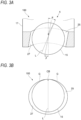
- each pocket 25 is inclined at an inclination angle ⁇ larger than 0 degrees.
- the ball 15 in the pocket 25 has contact points CA with the cylindrical surface 27 at which a plane passing through the center of the ball 15 and orthogonal to the inclination angle ⁇ intersects with respect to the cylindrical surface 27.
- the inclination angle ⁇ of the cylindrical surface 27 is the same for all the pockets 25.
- the inclination angle ⁇ of the cylindrical surface 27 is smaller than the contact angle ⁇ of the ball 15 when an axial preload is applied. That is, the inclination angle ⁇ of the cylindrical surface 27 of the pocket 25 is an angle satisfying the following formula (1). 0 ° ⁇ ⁇ ⁇ ⁇ ⁇
- a ratio Ct/Db of a dimension Ct between the contact point CA and the nearest end E of the pocket 25 to a diameter Db of the ball 15 is preferably 0.05 or more and 0.4 or less.
- the dimension Ct represents a length along the central axis of the cylindrical surface 27. That is, the ratio Ct/Db of the dimension Ct between the contact point CA and the nearest end E of the pocket 25 to the diameter Db of the ball 15 preferably satisfies the following formula (2). 0.05 ⁇ Ct / Db ⁇ 0.4
- the ratio Ct/Db of the dimension Ct between the contact point CA and the nearest end E of the pocket 25 to the diameter Db of the ball is set to 0.05 or more and 0.4 or less as in the above formula (2), a narrow region between the ball 15 and the cylindrical surface 27 of the pocket 25 can be secured around the contact point CA at which the ball 15 and the cylindrical surface 27 of the pocket 25 come into contact with each other. Therefore, it is possible to sufficiently secure a lubricant at the contact point CA at which the ball 15 and the cylindrical surface 27 of the pocket 25 come into contact with each other.
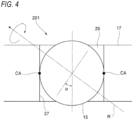
- a ball bearing 201 according to Reference Example 1 shown in Fig. 4 is a general ball bearing in which a central axis of the pocket 25 of the cage 17 is parallel to the central axis along the radial direction of the cage 17.
- the contact points CA between the cylindrical surface 27 of the pocket 25 and the ball 15 is located at positions far away from the rotation axis R. That is, the ball 15 and the cylindrical surface 27 of the pocket 25 of the cage 17 come into contact with each other at positions where the rotation circumferential speed is high.
- the inclination angle ⁇ of the cylindrical surface 27 of the pocket 25 is larger than 0°, so that the contact points CA between the ball 15 and the cylindrical surface 27 are close to the rotation axis R of the ball 15, and thus are located at positions where the rotation circumferential speed of the ball 15 is relatively small (see Fig. 1 ). Therefore, it is possible to obtain a greater effect of improving the bearing performance, such as a reduction in sliding friction between the balls 15 and the cage 17, a reduction in rotational torque, a reduction in heat generation between the balls 15 and the cage 17, an extension of the life of the lubricant due to the reduction in heat generation, a reduction in wear of the cage 17, and a reduction in vibration of the cage. In order to obtain a greater effect of improving the bearing performance, it is preferable that 3° ⁇ ⁇ , and it is more preferable that 5° ⁇ ⁇ .
- a central axis P of the pocket 25 of the cage 17 is parallel to a central axis Q along the radial direction of the cage 17 (coincides with the case shown in Fig. 5 ). Therefore, as shown in (B) of Fig. 5 , when viewed from the outer circumferential side or the inner circumferential side along the running line L of the ball 15 inclined at the contact angle ⁇ , the gaps G on both sides of the contact portion CB between the pocket 25 and the ball 15 are different. As a result, lubrication by the lubricant between the ball 15 and the cylindrical surface 27 of the pocket 25 of the cage 17 becomes unstable, and there is a concern that the cage 17 may vibrate and that rotation balance of the cage 17 may be lost.
- the ball bearing 100 of the present configuration example since the cylindrical surface 27 of the pocket 25 is inclined at the inclination angle ⁇ , the balanced and nearly uniform gap G is provided on both sides of the contact portion CB between the pocket 25 and the ball 15 when viewed from the running line of the ball 15 (see (A) and (B) of Fig. 3 ). As a result, good lubrication by the lubricant between the ball 15 and the cylindrical surface 27 of the pocket 25 of the cage 17 is possible, occurrence of vibration of the cage 17 is reduced, and the cage 17 is rotated in a balanced manner.
- the inclination angle ⁇ of the pocket 25 of the cage 17 is equal to the contact angle ⁇ when an axial preload is applied.
- the space S from the contact point CA between the ball 15 and the cage 17 to a circumferential surface on a side close to the cage 17 is narrowed.
- a sufficient amount of lubricant is not secured at the contact portion between the cylindrical surface 27 of the pocket 25 of the cage 17 and the ball 15, which may lead to a decrease in bearing performance.
- the lubricant can be sufficiently secured at the contact point CA between the ball 15 and the cage 17, and it is possible to obtain the effect of improving the bearing performance, such as a reduction in sliding friction between the balls 15 and the pockets 25 of the cage 17, a reduction in rotational torque, a reduction in heat generation between the balls 15 and the cage 17, an extension of the life of the lubricant due to the reduction in heat generation, a reduction in wear of the cage 17, and a reduction in vibration of the cage.
- a structure including the cage 17 in which the cylindrical pockets 25 are penetrated from front and back is exemplified, but a shape of the cage 17 is not limited to the shape including the cylindrical pockets 25 penetrating through the front and the back.
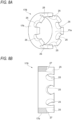
- the cage may be a crown-type cage 17Ain which the pockets 25 are open at one circumferential edge.
- a cage 17B shown in (A) and (B) of Fig. 8 is a crown-type cage in which the cylindrical surface 27 of the pocket 25 is inclined at the inclination angle ⁇ in a direction away from the opened one circumferential edge toward the outer circumferential side.
- the contact point CA between the ball 15 and the cylindrical surface 27 can be disposed at a position where the rotation circumferential speed of the ball 15 is relatively small, and a space SA from the contact point CA between the ball 15 and the cylindrical surface 27 to the circumferential surface on a side close to the cages 17A and 17B can be widened.
- the ball bearing 100 of the present configuration example may be a deep groove ball bearing, an angular contact bearing, or the like, and the type, size, and internal specifications are not limited.
- the present invention is not limited to the embodiment described above, and combinations of the respective configurations of the embodiment and modifications and applications made by those skilled in the art based on the description of the specification and well-known techniques are also intended by the present invention and are included in the scope of the protection.
- the ball bearing since the inclination angle ⁇ of the cylindrical surface of the pocket is larger than 0°, the ball and the pocket are brought into contact with each other at a position where the rotation circumferential speed of the ball is relatively small.
- the inclination angle ⁇ of the cylindrical surface of the pocket is smaller than the contact angle ⁇ of the ball when an axial preload is applied, so that the space from the contact portion between the ball and the cage to the nearest circumferential surface of the cage is widened, and a sufficient amount of lubricant can be secured in the contact portion between the ball and the cage.
- the inner diameter surface of the outer ring or the outer diameter surface of the inner ring that guides the cage has the same diameter on both sides in an axial direction across the outer ring raceway surface or the inner ring raceway surface, and an outer circumferential surface of the cage guided by the inner diameter surface of the outer ring or an inner circumferential surface of the cage guided by the outer diameter surface of the inner ring has the same diameter on one side in the axial direction and the other side in the axial direction.
- the cage guided by the inner diameter surface of the outer ring or the outer diameter surface of the inner ring is less likely to incline with respect to the outer ring or the inner ring.
- a radial thickness of the cage on the one side in the axial direction is equal to a radial thickness of the cage on the other side in the axial direction.
- the balance in the axial direction of the cage guided by the inner diameter surface of the outer ring or the outer diameter surface of the inner ring is made uniform, and the cage is less likely to incline with respect to the outer ring or the inner ring.
Landscapes
- Engineering & Computer Science (AREA)
- General Engineering & Computer Science (AREA)
- Mechanical Engineering (AREA)
- Rolling Contact Bearings (AREA)
Applications Claiming Priority (2)
| Application Number | Priority Date | Filing Date | Title |
|---|---|---|---|
| JP2021062335A JP7655047B2 (ja) | 2021-03-31 | 2021-03-31 | 玉軸受 |
| PCT/JP2022/006892 WO2022209417A1 (fr) | 2021-03-31 | 2022-02-21 | Roulement à billes |
Publications (3)
| Publication Number | Publication Date |
|---|---|
| EP4317719A1 true EP4317719A1 (fr) | 2024-02-07 |
| EP4317719A4 EP4317719A4 (fr) | 2024-10-16 |
| EP4317719B1 EP4317719B1 (fr) | 2026-04-01 |
Family
ID=83456013
Family Applications (1)
| Application Number | Title | Priority Date | Filing Date |
|---|---|---|---|
| EP22779644.8A Active EP4317719B1 (fr) | 2021-03-31 | 2022-02-21 | Roulement à billes |
Country Status (5)
| Country | Link |
|---|---|
| US (1) | US12292081B2 (fr) |
| EP (1) | EP4317719B1 (fr) |
| JP (1) | JP7655047B2 (fr) |
| CN (1) | CN117083467A (fr) |
| WO (1) | WO2022209417A1 (fr) |
Family Cites Families (11)
| Publication number | Priority date | Publication date | Assignee | Title |
|---|---|---|---|---|
| SU518583A1 (ru) | 1972-07-11 | 1976-06-25 | Предприятие П/Я А-1586 | Радиально-упорный шарикоподшипник с посто нным углом контакта |
| DE2612272A1 (de) * | 1976-03-19 | 1977-09-22 | Universal Kugellager Gmbh | Axial-schraegkugellager |
| JPH0743487Y2 (ja) * | 1989-07-10 | 1995-10-09 | エヌティエヌ株式会社 | アンギュラ玉軸受 |
| JP2001140870A (ja) | 1999-11-19 | 2001-05-22 | Nsk Ltd | アンギュラ玉軸受 |
| US6540407B2 (en) * | 2001-06-12 | 2003-04-01 | Electric Boat Corporation | Rolling element bearing arrangement |
| JP2004301314A (ja) * | 2003-04-01 | 2004-10-28 | Nsk Ltd | 転がり軸受 |
| JP5994369B2 (ja) * | 2012-05-01 | 2016-09-21 | 日本精工株式会社 | アンギュラ玉軸受 |
| TWI550200B (zh) * | 2014-12-18 | 2016-09-21 | Nsk Ltd | Bevel ball bearing |
| TW202020329A (zh) * | 2018-10-15 | 2020-06-01 | 日商日本精工股份有限公司 | 斜角滾珠軸承 |
| JP7314701B2 (ja) * | 2019-08-07 | 2023-07-26 | 日本精工株式会社 | 深溝玉軸受 |
| JP2021062335A (ja) | 2019-10-11 | 2021-04-22 | 昭和電工マテリアルズ株式会社 | 反応生成物の製造方法及び製造装置 |
-
2021
- 2021-03-31 JP JP2021062335A patent/JP7655047B2/ja active Active
-
2022
- 2022-02-21 WO PCT/JP2022/006892 patent/WO2022209417A1/fr not_active Ceased
- 2022-02-21 CN CN202280024503.5A patent/CN117083467A/zh active Pending
- 2022-02-21 US US18/270,952 patent/US12292081B2/en active Active
- 2022-02-21 EP EP22779644.8A patent/EP4317719B1/fr active Active
Also Published As
| Publication number | Publication date |
|---|---|
| JP2022157867A (ja) | 2022-10-14 |
| CN117083467A (zh) | 2023-11-17 |
| WO2022209417A1 (fr) | 2022-10-06 |
| US12292081B2 (en) | 2025-05-06 |
| US20240052881A1 (en) | 2024-02-15 |
| JP7655047B2 (ja) | 2025-04-02 |
| EP4317719B1 (fr) | 2026-04-01 |
| EP4317719A4 (fr) | 2024-10-16 |
Similar Documents
| Publication | Publication Date | Title |
|---|---|---|
| EP2270347B1 (fr) | Roulement à billes | |
| CN103228938B (zh) | 保持架以及滚动轴承 | |
| US8292512B2 (en) | Ball bearing and supporting construction | |
| US8939649B2 (en) | Rolling bearing | |
| EP3543553A1 (fr) | Cage de palier à roulement et palier à roulement | |
| US20090290826A1 (en) | Rolling element bearing with different guide pockets | |
| US11655853B2 (en) | Bearing cage and bearing | |
| US7364365B2 (en) | Conrad bearing cage | |
| CN108626251B (zh) | 滚动轴承 | |
| JP2022036002A (ja) | 玉軸受 | |
| EP1367277B1 (fr) | Système de maintien avec des poches présentants une symétrie de révolution | |
| EP1975432B1 (fr) | Roulement à billes | |
| EP4317719A1 (fr) | Roulement à billes | |
| WO2019151456A1 (fr) | Roulement à billes et unité de roulement | |
| JP2009275722A (ja) | 転がり軸受 | |
| JP4122474B2 (ja) | 保持器 | |
| JP7806546B2 (ja) | 玉軸受 | |
| JP7314701B2 (ja) | 深溝玉軸受 | |
| JPH1082424A (ja) | 転がり軸受用保持器 | |
| WO2013018654A1 (fr) | Roulement radial à billes | |
| JP5985684B2 (ja) | スラスト軸受及びその保持器 | |
| EP4663965A1 (fr) | Palier à roulement et dispositif à broche pour machine-outil | |
| CN121569123A (zh) | 球轴承 | |
| JPS61160628A (ja) | 高速アンギユラ玉軸受 | |
| JP2026028457A (ja) | ころ軸受 |
Legal Events
| Date | Code | Title | Description |
|---|---|---|---|
| STAA | Information on the status of an ep patent application or granted ep patent |
Free format text: STATUS: THE INTERNATIONAL PUBLICATION HAS BEEN MADE |
|
| PUAI | Public reference made under article 153(3) epc to a published international application that has entered the european phase |
Free format text: ORIGINAL CODE: 0009012 |
|
| STAA | Information on the status of an ep patent application or granted ep patent |
Free format text: STATUS: REQUEST FOR EXAMINATION WAS MADE |
|
| 17P | Request for examination filed |
Effective date: 20230710 |
|
| AK | Designated contracting states |
Kind code of ref document: A1 Designated state(s): AL AT BE BG CH CY CZ DE DK EE ES FI FR GB GR HR HU IE IS IT LI LT LU LV MC MK MT NL NO PL PT RO RS SE SI SK SM TR |
|
| DAV | Request for validation of the european patent (deleted) | ||
| DAX | Request for extension of the european patent (deleted) | ||
| A4 | Supplementary search report drawn up and despatched |
Effective date: 20240918 |
|
| RIC1 | Information provided on ipc code assigned before grant |
Ipc: F16C 33/66 20060101ALI20240912BHEP Ipc: F16C 33/38 20060101ALI20240912BHEP Ipc: F16C 19/16 20060101AFI20240912BHEP |
|
| GRAP | Despatch of communication of intention to grant a patent |
Free format text: ORIGINAL CODE: EPIDOSNIGR1 |
|
| STAA | Information on the status of an ep patent application or granted ep patent |
Free format text: STATUS: GRANT OF PATENT IS INTENDED |
|
| INTG | Intention to grant announced |
Effective date: 20251120 |
|
| GRAS | Grant fee paid |
Free format text: ORIGINAL CODE: EPIDOSNIGR3 |
|
| GRAA | (expected) grant |
Free format text: ORIGINAL CODE: 0009210 |
|
| STAA | Information on the status of an ep patent application or granted ep patent |
Free format text: STATUS: THE PATENT HAS BEEN GRANTED |
|
| AK | Designated contracting states |
Kind code of ref document: B1 Designated state(s): AL AT BE BG CH CY CZ DE DK EE ES FI FR GB GR HR HU IE IS IT LI LT LU LV MC MK MT NL NO PL PT RO RS SE SI SK SM TR |
|
| REG | Reference to a national code |
Ref country code: CH Ref legal event code: F10 Free format text: ST27 STATUS EVENT CODE: U-0-0-F10-F00 (AS PROVIDED BY THE NATIONAL OFFICE) Effective date: 20260401 Ref country code: GB Ref legal event code: FG4D |
|
| REG | Reference to a national code |
Ref country code: IE Ref legal event code: FG4D |
|
| REG | Reference to a national code |
Ref country code: DE Ref legal event code: R096 Ref document number: 602022033597 Country of ref document: DE |