EP4317731A1 - Untersetzungsgetriebe - Google Patents
Untersetzungsgetriebe Download PDFInfo
- Publication number
- EP4317731A1 EP4317731A1 EP22774755.7A EP22774755A EP4317731A1 EP 4317731 A1 EP4317731 A1 EP 4317731A1 EP 22774755 A EP22774755 A EP 22774755A EP 4317731 A1 EP4317731 A1 EP 4317731A1
- Authority
- EP
- European Patent Office
- Prior art keywords
- notch
- locking member
- ring nut
- press
- fitted
- Prior art date
- Legal status (The legal status is an assumption and is not a legal conclusion. Google has not performed a legal analysis and makes no representation as to the accuracy of the status listed.)
- Pending
Links
Images



Classifications
-
- F—MECHANICAL ENGINEERING; LIGHTING; HEATING; WEAPONS; BLASTING
- F16—ENGINEERING ELEMENTS AND UNITS; GENERAL MEASURES FOR PRODUCING AND MAINTAINING EFFECTIVE FUNCTIONING OF MACHINES OR INSTALLATIONS; THERMAL INSULATION IN GENERAL
- F16C—SHAFTS; FLEXIBLE SHAFTS; ELEMENTS OR CRANKSHAFT MECHANISMS; ROTARY BODIES OTHER THAN GEARING ELEMENTS; BEARINGS
- F16C35/00—Rigid support of bearing units; Housings, e.g. caps, covers
- F16C35/04—Rigid support of bearing units; Housings, e.g. caps, covers in the case of ball or roller bearings
- F16C35/06—Mounting or dismounting of ball or roller bearings; Fixing them onto shaft or in housing
- F16C35/07—Fixing them on the shaft or housing with interposition of an element
- F16C35/077—Fixing them on the shaft or housing with interposition of an element between housing and outer race ring
-
- F—MECHANICAL ENGINEERING; LIGHTING; HEATING; WEAPONS; BLASTING
- F16—ENGINEERING ELEMENTS AND UNITS; GENERAL MEASURES FOR PRODUCING AND MAINTAINING EFFECTIVE FUNCTIONING OF MACHINES OR INSTALLATIONS; THERMAL INSULATION IN GENERAL
- F16B—DEVICES FOR FASTENING OR SECURING CONSTRUCTIONAL ELEMENTS OR MACHINE PARTS TOGETHER, e.g. NAILS, BOLTS, CIRCLIPS, CLAMPS, CLIPS OR WEDGES; JOINTS OR JOINTING
- F16B39/00—Locking of screws, bolts or nuts
- F16B39/02—Locking of screws, bolts or nuts in which the locking takes place after screwing down
- F16B39/04—Locking of screws, bolts or nuts in which the locking takes place after screwing down with a member penetrating the screw-threaded surface of at least one part, e.g. a pin, a wedge, cotter-pin, screw
-
- B—PERFORMING OPERATIONS; TRANSPORTING
- B60—VEHICLES IN GENERAL
- B60K—ARRANGEMENT OR MOUNTING OF PROPULSION UNITS OR OF TRANSMISSIONS IN VEHICLES; ARRANGEMENT OR MOUNTING OF PLURAL DIVERSE PRIME-MOVERS IN VEHICLES; AUXILIARY DRIVES FOR VEHICLES; INSTRUMENTATION OR DASHBOARDS FOR VEHICLES; ARRANGEMENTS IN CONNECTION WITH COOLING, AIR INTAKE, GAS EXHAUST OR FUEL SUPPLY OF PROPULSION UNITS IN VEHICLES
- B60K17/00—Arrangement or mounting of transmissions in vehicles
- B60K17/04—Arrangement or mounting of transmissions in vehicles characterised by arrangement, location or kind of gearing
- B60K17/043—Transmission unit disposed in on near the vehicle wheel, or between the differential gear unit and the wheel
- B60K17/046—Transmission unit disposed in on near the vehicle wheel, or between the differential gear unit and the wheel with planetary gearing having orbital motion
-
- F—MECHANICAL ENGINEERING; LIGHTING; HEATING; WEAPONS; BLASTING
- F16—ENGINEERING ELEMENTS AND UNITS; GENERAL MEASURES FOR PRODUCING AND MAINTAINING EFFECTIVE FUNCTIONING OF MACHINES OR INSTALLATIONS; THERMAL INSULATION IN GENERAL
- F16B—DEVICES FOR FASTENING OR SECURING CONSTRUCTIONAL ELEMENTS OR MACHINE PARTS TOGETHER, e.g. NAILS, BOLTS, CIRCLIPS, CLAMPS, CLIPS OR WEDGES; JOINTS OR JOINTING
- F16B39/00—Locking of screws, bolts or nuts
- F16B39/02—Locking of screws, bolts or nuts in which the locking takes place after screwing down
- F16B39/10—Locking of screws, bolts or nuts in which the locking takes place after screwing down by a plate, spring, wire or ring immovable with regard to the bolt or object and mainly perpendicular to the axis of the bolt
-
- F—MECHANICAL ENGINEERING; LIGHTING; HEATING; WEAPONS; BLASTING
- F16—ENGINEERING ELEMENTS AND UNITS; GENERAL MEASURES FOR PRODUCING AND MAINTAINING EFFECTIVE FUNCTIONING OF MACHINES OR INSTALLATIONS; THERMAL INSULATION IN GENERAL
- F16C—SHAFTS; FLEXIBLE SHAFTS; ELEMENTS OR CRANKSHAFT MECHANISMS; ROTARY BODIES OTHER THAN GEARING ELEMENTS; BEARINGS
- F16C35/00—Rigid support of bearing units; Housings, e.g. caps, covers
- F16C35/04—Rigid support of bearing units; Housings, e.g. caps, covers in the case of ball or roller bearings
- F16C35/06—Mounting or dismounting of ball or roller bearings; Fixing them onto shaft or in housing
- F16C35/07—Fixing them on the shaft or housing with interposition of an element
- F16C35/073—Fixing them on the shaft or housing with interposition of an element between shaft and inner race ring
-
- F—MECHANICAL ENGINEERING; LIGHTING; HEATING; WEAPONS; BLASTING
- F16—ENGINEERING ELEMENTS AND UNITS; GENERAL MEASURES FOR PRODUCING AND MAINTAINING EFFECTIVE FUNCTIONING OF MACHINES OR INSTALLATIONS; THERMAL INSULATION IN GENERAL
- F16H—GEARING
- F16H57/00—General details of gearing
- F16H57/02—Gearboxes; Mounting gearing therein
- F16H57/021—Shaft support structures, e.g. partition walls, bearing eyes, casing walls or covers with bearings
- F16H57/022—Adjustment of gear shafts or bearings
-
- F—MECHANICAL ENGINEERING; LIGHTING; HEATING; WEAPONS; BLASTING
- F16—ENGINEERING ELEMENTS AND UNITS; GENERAL MEASURES FOR PRODUCING AND MAINTAINING EFFECTIVE FUNCTIONING OF MACHINES OR INSTALLATIONS; THERMAL INSULATION IN GENERAL
- F16H—GEARING
- F16H57/00—General details of gearing
- F16H57/02—Gearboxes; Mounting gearing therein
- F16H57/023—Mounting or installation of gears or shafts in the gearboxes, e.g. methods or means for assembly
-
- B—PERFORMING OPERATIONS; TRANSPORTING
- B60—VEHICLES IN GENERAL
- B60K—ARRANGEMENT OR MOUNTING OF PROPULSION UNITS OR OF TRANSMISSIONS IN VEHICLES; ARRANGEMENT OR MOUNTING OF PLURAL DIVERSE PRIME-MOVERS IN VEHICLES; AUXILIARY DRIVES FOR VEHICLES; INSTRUMENTATION OR DASHBOARDS FOR VEHICLES; ARRANGEMENTS IN CONNECTION WITH COOLING, AIR INTAKE, GAS EXHAUST OR FUEL SUPPLY OF PROPULSION UNITS IN VEHICLES
- B60K7/00—Disposition of motor in, or adjacent to, traction wheel
- B60K2007/0038—Disposition of motor in, or adjacent to, traction wheel the motor moving together with the wheel axle
-
- B—PERFORMING OPERATIONS; TRANSPORTING
- B60—VEHICLES IN GENERAL
- B60K—ARRANGEMENT OR MOUNTING OF PROPULSION UNITS OR OF TRANSMISSIONS IN VEHICLES; ARRANGEMENT OR MOUNTING OF PLURAL DIVERSE PRIME-MOVERS IN VEHICLES; AUXILIARY DRIVES FOR VEHICLES; INSTRUMENTATION OR DASHBOARDS FOR VEHICLES; ARRANGEMENTS IN CONNECTION WITH COOLING, AIR INTAKE, GAS EXHAUST OR FUEL SUPPLY OF PROPULSION UNITS IN VEHICLES
- B60K7/00—Disposition of motor in, or adjacent to, traction wheel
- B60K2007/0092—Disposition of motor in, or adjacent to, traction wheel the motor axle being coaxial to the wheel axle
-
- B—PERFORMING OPERATIONS; TRANSPORTING
- B60—VEHICLES IN GENERAL
- B60K—ARRANGEMENT OR MOUNTING OF PROPULSION UNITS OR OF TRANSMISSIONS IN VEHICLES; ARRANGEMENT OR MOUNTING OF PLURAL DIVERSE PRIME-MOVERS IN VEHICLES; AUXILIARY DRIVES FOR VEHICLES; INSTRUMENTATION OR DASHBOARDS FOR VEHICLES; ARRANGEMENTS IN CONNECTION WITH COOLING, AIR INTAKE, GAS EXHAUST OR FUEL SUPPLY OF PROPULSION UNITS IN VEHICLES
- B60K7/00—Disposition of motor in, or adjacent to, traction wheel
- B60K7/0015—Disposition of motor in, or adjacent to, traction wheel the motor being hydraulic
-
- B—PERFORMING OPERATIONS; TRANSPORTING
- B60—VEHICLES IN GENERAL
- B60Y—INDEXING SCHEME RELATING TO ASPECTS CROSS-CUTTING VEHICLE TECHNOLOGY
- B60Y2200/00—Type of vehicle
- B60Y2200/40—Special vehicles
- B60Y2200/41—Construction vehicles, e.g. graders, excavators
- B60Y2200/412—Excavators
-
- F—MECHANICAL ENGINEERING; LIGHTING; HEATING; WEAPONS; BLASTING
- F16—ENGINEERING ELEMENTS AND UNITS; GENERAL MEASURES FOR PRODUCING AND MAINTAINING EFFECTIVE FUNCTIONING OF MACHINES OR INSTALLATIONS; THERMAL INSULATION IN GENERAL
- F16C—SHAFTS; FLEXIBLE SHAFTS; ELEMENTS OR CRANKSHAFT MECHANISMS; ROTARY BODIES OTHER THAN GEARING ELEMENTS; BEARINGS
- F16C19/00—Bearings with rolling contact, for exclusively rotary movement
- F16C19/02—Bearings with rolling contact, for exclusively rotary movement with bearing balls essentially of the same size in one or more circular rows
- F16C19/14—Bearings with rolling contact, for exclusively rotary movement with bearing balls essentially of the same size in one or more circular rows for both radial and axial load
- F16C19/18—Bearings with rolling contact, for exclusively rotary movement with bearing balls essentially of the same size in one or more circular rows for both radial and axial load with two or more rows of balls
- F16C19/181—Bearings with rolling contact, for exclusively rotary movement with bearing balls essentially of the same size in one or more circular rows for both radial and axial load with two or more rows of balls with angular contact
- F16C19/183—Bearings with rolling contact, for exclusively rotary movement with bearing balls essentially of the same size in one or more circular rows for both radial and axial load with two or more rows of balls with angular contact with two rows at opposite angles
- F16C19/184—Bearings with rolling contact, for exclusively rotary movement with bearing balls essentially of the same size in one or more circular rows for both radial and axial load with two or more rows of balls with angular contact with two rows at opposite angles in O-arrangement
-
- F—MECHANICAL ENGINEERING; LIGHTING; HEATING; WEAPONS; BLASTING
- F16—ENGINEERING ELEMENTS AND UNITS; GENERAL MEASURES FOR PRODUCING AND MAINTAINING EFFECTIVE FUNCTIONING OF MACHINES OR INSTALLATIONS; THERMAL INSULATION IN GENERAL
- F16C—SHAFTS; FLEXIBLE SHAFTS; ELEMENTS OR CRANKSHAFT MECHANISMS; ROTARY BODIES OTHER THAN GEARING ELEMENTS; BEARINGS
- F16C2226/00—Joining parts; Fastening; Assembling or mounting parts
- F16C2226/50—Positive connections
- F16C2226/60—Positive connections with threaded parts, e.g. bolt and nut connections
-
- F—MECHANICAL ENGINEERING; LIGHTING; HEATING; WEAPONS; BLASTING
- F16—ENGINEERING ELEMENTS AND UNITS; GENERAL MEASURES FOR PRODUCING AND MAINTAINING EFFECTIVE FUNCTIONING OF MACHINES OR INSTALLATIONS; THERMAL INSULATION IN GENERAL
- F16C—SHAFTS; FLEXIBLE SHAFTS; ELEMENTS OR CRANKSHAFT MECHANISMS; ROTARY BODIES OTHER THAN GEARING ELEMENTS; BEARINGS
- F16C2226/00—Joining parts; Fastening; Assembling or mounting parts
- F16C2226/50—Positive connections
- F16C2226/62—Positive connections with pins, bolts or dowels
-
- F—MECHANICAL ENGINEERING; LIGHTING; HEATING; WEAPONS; BLASTING
- F16—ENGINEERING ELEMENTS AND UNITS; GENERAL MEASURES FOR PRODUCING AND MAINTAINING EFFECTIVE FUNCTIONING OF MACHINES OR INSTALLATIONS; THERMAL INSULATION IN GENERAL
- F16C—SHAFTS; FLEXIBLE SHAFTS; ELEMENTS OR CRANKSHAFT MECHANISMS; ROTARY BODIES OTHER THAN GEARING ELEMENTS; BEARINGS
- F16C2229/00—Setting preload
-
- F—MECHANICAL ENGINEERING; LIGHTING; HEATING; WEAPONS; BLASTING
- F16—ENGINEERING ELEMENTS AND UNITS; GENERAL MEASURES FOR PRODUCING AND MAINTAINING EFFECTIVE FUNCTIONING OF MACHINES OR INSTALLATIONS; THERMAL INSULATION IN GENERAL
- F16C—SHAFTS; FLEXIBLE SHAFTS; ELEMENTS OR CRANKSHAFT MECHANISMS; ROTARY BODIES OTHER THAN GEARING ELEMENTS; BEARINGS
- F16C2361/00—Apparatus or articles in engineering in general
- F16C2361/61—Toothed gear systems, e.g. support of pinion shafts
-
- F—MECHANICAL ENGINEERING; LIGHTING; HEATING; WEAPONS; BLASTING
- F16—ENGINEERING ELEMENTS AND UNITS; GENERAL MEASURES FOR PRODUCING AND MAINTAINING EFFECTIVE FUNCTIONING OF MACHINES OR INSTALLATIONS; THERMAL INSULATION IN GENERAL
- F16H—GEARING
- F16H1/00—Toothed gearings for conveying rotary motion
- F16H1/28—Toothed gearings for conveying rotary motion with gears having orbital motion
- F16H1/46—Systems consisting of a plurality of gear trains each with orbital gears, i.e. systems having three or more central gears
-
- F—MECHANICAL ENGINEERING; LIGHTING; HEATING; WEAPONS; BLASTING
- F16—ENGINEERING ELEMENTS AND UNITS; GENERAL MEASURES FOR PRODUCING AND MAINTAINING EFFECTIVE FUNCTIONING OF MACHINES OR INSTALLATIONS; THERMAL INSULATION IN GENERAL
- F16H—GEARING
- F16H57/00—General details of gearing
- F16H57/02—Gearboxes; Mounting gearing therein
- F16H57/021—Shaft support structures, e.g. partition walls, bearing eyes, casing walls or covers with bearings
- F16H57/022—Adjustment of gear shafts or bearings
- F16H2057/0221—Axial adjustment
Definitions
- the present invention relates to a speed reducer.
- JP 2006-161753 A discloses a hydraulic motor with a speed reducer including a variable displacement swash plate type hydraulic motor and a speed reducer.
- a speed of rotation of the hydraulic motor is reduced by a planetary gear speed reduction mechanism of the speed reducer, the obtained rotation is transmitted to a casing of the speed reducer, and the casing of the speed reducer is rotated with a high torque.
- a bearing is provided between an outer peripheral surface of a casing of the hydraulic motor and an inner peripheral surface of the casing of the speed reducer, and the bearing rotatably supports the casing of the speed reducer with respect to the casing of the hydraulic motor. The bearing is retained by a nut screwed to a male screw portion of the casing of the hydraulic motor.
- the nut of the hydraulic motor with a speed reducer described in JP 2006-161753 A receives force in an axial direction from the bearing. Therefore, it is conceivable that with operation of the hydraulic motor with a speed reducer, the nut is loosened.
- the casing of the hydraulic motor is provided with an insertion hole, a part of which opens to the outer peripheral surface of the casing of the hydraulic motor and extends in an axial direction of the male screw portion of the casing of the hydraulic motor.
- a female screw portion to be screwed to the male screw portion of the plug is formed by tapping or the like. Since a part of the insertion hole opens to the outer peripheral surface of the casing of the hydraulic motor, in a state where the nut is screwed to the casing of the hydraulic motor, a part of a female screw portion of the nut faces the insertion hole. Therefore, by screw-fastening the plug to the insertion hole in this state, the male screw portion of the plug is bit into and engaged with the female screw portion of the nut. Accordingly, the nut is locked.
- the insertion hole is provided in the casing of the hydraulic motor, and the female screw portion is further formed in the insertion hole.
- burrs are generated in the opening when the female screw portion is formed in the insertion hole. Therefore, a step of removing the burrs is required. In this way, the locking mechanism for the nut as described above takes time and effort for processing.
- An object of the present invention is to easily lock a ring nut of a speed reducer.
- a speed reducer includes: a fixed housing that houses a drive source and includes a male screw portion on an outer peripheral surface; a rotating housing configured to rotate by transmission of output rotation of the drive source; a speed reduction mechanism housed in the rotating housing and configured to reduce a speed of the output rotation of the drive source and transmit the obtained output rotation to the rotating housing; a bearing member attached to the fixed housing and configured to rotatably support the rotating housing with respect to the fixed housing; a ring nut screwed to the male screw portion of the fixed housing and configured to retain the bearing member; and a locking member configured to lock the ring nut, the male screw portion is provided with a notch that opens to the outer peripheral surface of the fixed housing with a predetermined width and that extends in an axial direction, and the locking member is press-fitted between the notch and the ring nut, fixed in the notch, and engaged with the ring nut in a circumferential direction.
- a speed reducer 100 according to an embodiment of the present invention will be described with reference to the drawings.
- a speed reducer that reduces power of a hydraulic motor which is a drive source for traveling of a crawler type working machine such as a hydraulic excavator, and transmits the obtained power to a crawler belt will be described as an example.
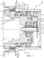
- the speed reducer 100 includes a fixed housing 10 that houses a hydraulic motor 9 as a drive source, a rotating housing 20 that is rotatably provided with respect to the fixed housing 10, and a speed reduction mechanism 30 that is housed in the rotating housing 20 and reduces a speed of output rotation of a shaft 31 of the hydraulic motor 9 and transmits the obtained output rotation to the rotating housing 20.
- the rotating housing 20 is a cylindrical member, and rotates by transmission of the output rotation of the hydraulic motor 9 via the speed reduction mechanism 30.
- the fixed housing 10 and the rotating housing 20 are disposed inside a path through which the crawler belt circulates.
- An annular rotating flange 29 protruding radially outward from an outer peripheral surface 22 is formed in the rotating housing 20.
- a sprocket (not illustrated) is fastened to the rotating flange 29 by bolts.
- the crawler belt meshes with the sprocket.
- the speed reducer 100 includes a bearing unit 40 as a bearing member provided between an outer periphery of the fixed housing 10 and an inner periphery of the rotating housing 20, and a ring nut 60 that retains the bearing unit 40.
- the bearing unit 40 includes a pair of bearings 41 that rotatably support the rotating housing 20 with respect to the fixed housing 10, and a stopper ring 49 having a circular sectional shape that restricts a relative movement between the bearings 41 and the rotating housing 20 in an axial direction.
- the pair of bearings 41 have the same configuration and are arranged symmetrically.
- Each of the bearings 41 is a single-row angular ball bearing in which a straight line connecting a contact point between a ball and an inner ring and a contact point between the ball and an outer ring forms a predetermined angle (contact angle) with respect to a radial direction.
- the pair of bearings 41 are attached to an outer peripheral surface of the fixed housing 10.
- the fixed housing 10 includes a step portion 16 and a male screw portion 17 on the outer peripheral surface.
- the ring nut 60 is screwed to the male screw portion 17 of the fixed housing 10.
- the pair of bearings 41 are sandwiched between the step portion 16 of the fixed housing 10 and the ring nut 60.
- the ring nut 60 receives force in the axial direction from the pair of bearings 41. Therefore, in order to prevent the ring nut 60 from being loosened due to operation of the speed reducer 100, the ring nut 60 is locked by a locking member 70 to be described later.
- the rotating housing 20 is rotatably supported by the pair of bearings 41 with respect to the fixed housing 10 fixed to a vehicle body 6 as an external member, and rotates about a rotating center axis O.
- the hydraulic motor 9 is housed inside a body portion 11 of the fixed housing 10.
- the hydraulic motor 9 is, for example, a swash plate type piston motor. Since the hydraulic motor 9 can have a known configuration, detailed description thereof will be omitted.
- the drive source may be other than the hydraulic motor, for example, may be an electric motor.
- a fixed flange 12 is formed in the fixed housing 10 in a manner of protruding from an outer peripheral surface of the body portion 11.
- the fixed housing 10 is fixed to the vehicle body 6 by attaching the fixed flange 12 to the vehicle body 6 by bolts.
- the speed reduction mechanism 30 is a planetary gear speed reduction mechanism that reduces the speed of the output rotation of the shaft 31 of the hydraulic motor 9 and transmits the obtained output rotation to the rotating housing 20, and includes a gear portion 38.
- the gear portion 38 includes a sun gear 32 provided on the shaft 31 of the hydraulic motor 9, an inner gear 33 provided on an inner wall of the rotating housing 20, a plurality of planetary gears 34 meshing with both the sun gear 32 and the inner gear 33, a planetary carrier 35 supporting each of the planetary gears 34, a second-stage sun gear 36 meshing with the planetary carrier 35, and a plurality of planetary gears 37 meshing with both the sun gear 36 and the inner gear 33.
- the planetary gear 37 is provided with a washer 39. The washer 39 may not be provided.
- a floating seal 50 that seals a gap between the fixed housing 10 and the rotating housing 20 is provided between the fixed housing 10 and the rotating housing 20.
- the floating seal 50 seals the gap such that oil in the speed reducer 100 is prevented from leaking to an outside when the rotating housing 20 rotates, and also prevents foreign matters such as mud from entering the speed reducer 100 from the outside.
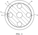
- FIG. 3 is a sectional view of the fixed housing 10 and the ring nut 60 as viewed from a section III illustrated in FIG. 1 , and illustrates a state before attachment of the locking member 70.
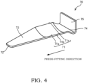
- FIG. 4 is a perspective view of the locking member 70.
- FIG. 5 is an enlarged sectional view illustrating a state after the attachment of the locking member 70, and corresponds to FIG. 2 .
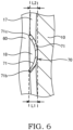
- FIG. 6 is a partial sectional view obtained by enlarging a VI part illustrated in FIG. 3 , and illustrates a state after the attachment of the locking member 70.
- the male screw portion 17 of the fixed housing 10 is provided with a notch 18 that opens to the outer peripheral surface of the fixed housing 10 with a predetermined width and that extends in the axial direction.
- two notches 18 are each formed in an arc shape in a section along the radial direction of the male screw portion 17, and are provided in the fixed housing 10 at positions facing each other with the shaft 31 of the hydraulic motor 9 sandwiched therebetween.
- Three or more notches 18 may be provided at equal intervals in a circumferential direction of the fixed housing 10.
- the notch 18 is formed such that a part of a curved surface portion 71 of the locking member 70 protrudes from the notch 18 beyond the outer peripheral surface of the fixed housing 10 in a state where the locking member 70 is press-fitted.
- the speed reducer 100 further includes the locking member 70 that locks the ring nut 60.
- the locking member 70 is formed of a metal having high hardness.
- the locking member 70 is press-fitted between an inner peripheral surface of the notch 18 and the ring nut 60, fixed in the notch 18, and engaged with the ring nut 60 in the circumferential direction. Accordingly, the ring nut 60 is locked.
- the locking member 70 is formed to extend in a press-fitting direction (arrow direction in FIG. 4 ) into the notch 18.
- the locking member 70 includes the arc-shaped curved surface portion 71, a distal end portion 72 first press-fitted into the notch 18 (in other words, end portion on a front side in the press-fitting direction), a tapered portion 73 in which a length corresponding to a width direction of the notch 18 is reduced toward the distal end portion 72 in a state of being press-fitted into the notch 18, an end portion 74 opposite to the distal end portion 72 in the press-fitting direction into the notch 18, and a head portion 75 provided to protrude from the end portion 74.
- the tapered portion 73 is formed such that a length in a tangential direction connecting two open ends to the outer peripheral surface of the fixed housing 10 in the notch 18 is reduced toward the distal end portion 72 in the state of being press-fitted into the notch 18.
- the tapered portion 73 is provided between the distal end portion 72 and the curved surface portion 71, and is formed in a curved surface shape continuous with the curved surface portion 71.
- the head portion 75 protrudes from the end portion 74 to a radial outer side of the male screw portion 17 in a state of being press-fitted into the notch 18.
- the locking member 70 is formed in an L shape so as to extend in the press-fitting direction into the notch 18 and to be bent in the radial direction of the male screw portion 17 in a state of being press-fitted into the notch 18.
- the locking member 70 is press-fitted into the notch 18 from the tapered portion 73 with an inner peripheral surface 71a of the curved surface portion 71 facing the radial outer side of the male screw portion 17. Since the head portion 75 of the locking member 70 extends perpendicularly to the press-fitting direction into the notch 18, by applying a load to the head portion 75 by driving the head portion 75 or the like, the locking member 70 can be easily press-fitted into the notch 18. Then, the load is applied to the head portion 75 until the curved surface portion 71 is press-fitted into the notch 18. In this way, the curved surface portion 71 is press-fitted into the notch 18 with the inner peripheral surface 71a facing the radial outer side of the male screw portion 17.
- the notch 18 is formed such that a part of the curved surface portion 71 of the locking member 70 (specifically, both end portions of the curved surface portion 71 in the circumferential direction) protrudes from the notch 18 to the radial outer side beyond the outer peripheral surface of the fixed housing 10 in a state where the locking member 70 is press-fitted.
- a length L1 of the curved surface portion 71 of the locking member 70 in the radial direction of the male screw portion 17 is larger than a depth L2 of the notch 18 in the radial direction of the male screw portion 17.
- the locking member 70 when the locking member 70 is press-fitted into the notch 18 in the state where the ring nut 60 is screwed to the male screw portion 17, a portion of the curved surface portion 71 protruding from the notch 18 is bit into a female screw portion of the ring nut 60 and is engaged with the female screw portion in the circumferential direction. Accordingly, the locking member 70 is fixed in the notch 18 and locks the ring nut 60.
- Such a locking mechanism for the ring nut 60 is formed by providing the notch 18 on the male screw portion 17 of the fixed housing 10. Specifically, in the speed reducer 100 according to the present embodiment, first, the notch 18 is formed on a portion where the ring nut 60 is attached to the outer peripheral surface of the fixed housing 10. Thereafter, the male screw portion 17 is formed on the outer peripheral surface of the fixed housing 10 including the notch 18. No male screw portion is formed on the inner peripheral surface of the notch 18.
- a ring nut is locked by a locking member including a male screw portion.
- a locking member including a male screw portion.
- an insertion hole having a part opening to an outer peripheral surface of a fixed housing and extending in an axial direction of a male screw portion of the fixed housing is provided, and a female screw portion to be screwed to a male screw portion of a plug by tapping or the like is provided in the insertion hole. Then, by screw-fastening the locking member to the insertion hole in a state where the ring nut is screwed to the male screw portion of the fixed housing, the male screw portion of the locking member is bit into and engaged with a female screw portion of the ring nut, and the ring nut is locked.
- the locking member 70 is press-fitted into the notch 18 and fixed in the notch 18. Therefore, a step of forming the female screw portion for locking the ring nut 60 is not required, and the step of removing the burrs is also eliminated. Therefore, the ring nut 60 can be easily locked with a small number of man-hours.
- the curved surface portion 71 of the locking member 70 is press-fitted into the notch 18 with the inner peripheral surface 71a facing to the radial outer side of the male screw portion 17, two portions, i.e., both end portions of the curved surface portion 71 in the circumferential direction are engaged with the ring nut 60. Specifically, two corner portions between the inner peripheral surface 71a of the curved surface portion 71 and both side surfaces 71b and 71c (see FIG. 6 ) of the curved surface portion 71 are bit into and engaged with the female screw portion of the ring nut 60. Therefore, the ring nut 60 can be more reliably locked.
- the locking member 70 since the locking member 70 includes the tapered portion 73 in which the length corresponding to the width direction of the notch 18 is reduced toward the distal end portion 72 in the state of being press-fitted into the notch 18 and the tapered portion 73 is press-fitted into the notch 18 from the distal end portion 72, the locking member 70 can be easily press-fitted into the notch 18.
- the locking member 70 may not include the tapered portion 73. In addition, the locking member 70 may not include the head portion 75 as long as the load can be applied until the curved surface portion 71 is press-fitted into the notch 18.
- the gear portion 38 of the speed reduction mechanism 30 is provided on the fixed housing 10 to intersect an extension line of the notch 18.
- the notch 18 and the gear portion 38 face each other without any other member sandwiched therebetween in the axial direction of the male screw portion 17.
- a distance between the gear portion 38 and the ring nut 60 in the axial direction of the male screw portion 17 is smaller than a length of the locking member 70 in the press-fitting direction into the notch 18.
- the locking member 70 press-fitted into the notch 18 receives force in a direction of falling off the notch 18, the locking member 70 comes into contact with the gear portion 38 (specifically, the planetary gear 37 or the washer 39 provided on the planetary gear 37) before falling off the notch 18. Accordingly, the locking member 70 is prevented from falling off the notch 18.
- the ring nut 60 is locked. Since the locking member 70 is press-fitted into the notch 18 and fixed in the notch 18, the step of forming the female screw portion for locking the ring nut 60 is not required, and the step of removing the burrs is also eliminated. Therefore, the ring nut 60 can be easily locked with a small number of man-hours.
- the head portion 75 of the locking member 70 extends perpendicularly to the press-fitting direction into the notch 18. Therefore, by applying the load to the head portion 75, the locking member 70 can be easily press-fitted into the notch 18.
- the curved surface portion 71 is press-fitted into the notch 18, and two portions, i.e., both end portions of the curved surface portion 71 in the circumferential direction are engaged with the ring nut 60. Therefore, the ring nut 60 can be more reliably locked.
- the locking member 70 includes the tapered portion 73 in which the length corresponding to the width direction of the notch 18 is reduced toward the distal end portion 72 in the state of being press-fitted into the notch 18, and is press-fitted into the notch 18 from the tapered portion 73. Therefore, the locking member 70 is easily press-fitted into the notch 18.
- the speed reduction mechanism 30 includes the gear portion 38 provided to intersect the extension line of the notch 18, and the distance between the gear portion 38 and the ring nut 60 in the axial direction of the male screw portion 17 is smaller than the length of the locking member 70 in the press-fitting direction into the notch 18. Accordingly, even if the locking member 70 press-fitted into the notch 18 receives the force in the direction of falling off the notch 18, the locking member 70 comes into contact with the gear portion 38 before falling off the notch 18. Therefore, the locking member 70 is prevented from falling off the notch 18.
- the locking member 70 in the above embodiment includes the arc-shaped curved surface portion 71 and the curved surface-shaped tapered portion 73 continuous with the curved surface portion 71.
- the locking member 70 may not include the arc-shaped curved surface portion 71 and instead, may include a flat surface portion 171 having a flat shape, and the tapered portion 73 may be formed in a flat shape continuous with the flat surface portion 171.
- the flat surface portion 171 of the locking member 70 may be bit into a female screw portion of the ring nut 60 and engaged with the female screw portion in the circumferential direction.
- the notch 18 is formed in a triangular shape in a section along a radial direction of the male screw portion 17.
- the locking member 70 is press-fitted into the notch 18 such that an inner peripheral surface of the notch 18 and the flat surface portion 171 of the locking member 70 are in contact with each other, and one corner portion of the flat surface portion 171 of the locking member 70 is bit into the female screw portion of the ring nut 60 and engaged with the female screw portion of the ring nut 60 in the circumferential direction.
- the speed reducer 100 includes: the fixed housing 10 that houses the hydraulic motor 9 as a drive source and includes the male screw portion 17 on the outer peripheral surface; the rotating housing 20 configured to rotate by the transmission of the output rotation of the hydraulic motor 9; the speed reduction mechanism 30 housed in the rotating housing 20 and configured to reduce the speed of the output rotation of the hydraulic motor 9 and transmit the obtained output rotation to the rotating housing 20; the bearing unit 40 as a bearing member attached to the fixed housing 10 and configured to rotatably support the rotating housing 20 with respect to the fixed housing 10; the ring nut 60 screwed to the male screw portion 17 of the fixed housing 10 and configured to retain the bearing unit 40; and the locking member 70 configured to lock the ring nut 60.
- the male screw portion 17 is provided with the notch 18 that opens to the outer peripheral surface of the fixed housing 10 with the predetermined width and that extends in the axial direction.
- the locking member 70 is press-fitted between the notch 18 and the ring nut 60, is fixed in the notch 18, and is engaged with the ring nut 60 in the circumferential direction.
- the ring nut 60 is locked. Since the locking member 70 is press-fitted into the notch 18 and fixed in the notch 18, the step of forming the female screw portion for locking the ring nut 60 is not required, and the step of removing the burrs is also eliminated. Therefore, the ring nut 60 can be easily locked with a small number of man-hours.
- the locking member 70 includes the arc-shaped curved surface portion 71, and the curved surface portion 71 is press-fitted into the notch 18 with the inner peripheral surface 71a facing the radial outer side of the male screw portion 17.
- the locking member 70 is press-fitted into the notch 18, and two portions, i.e., two end portions of the curved surface portion 71 are engaged with the ring nut 60. Therefore, the ring nut 60 can be more reliably locked.
- the locking member 70 includes the tapered portion 73 in which the length corresponding to the width direction of the notch 18 is reduced toward the distal end portion 72 in the state of being press-fitted into the notch 18, and the tapered portion 73 is press-fitted into the notch 18 from the distal end portion 72.
- the locking member 70 is easily press-fitted into the notch 18 by the tapered portion 73.
- the speed reduction mechanism 30 includes the gear portion 38 provided to intersect the extension line of the notch 18, and the distance between the gear portion 38 and the ring nut 60 in the axial direction is smaller than the length of the locking member 70 in the press-fitting direction into the notch 18.
- the locking member 70 is prevented from falling off the notch 18 by the gear portion 38 of the speed reduction mechanism 30.
Landscapes
- Engineering & Computer Science (AREA)
- General Engineering & Computer Science (AREA)
- Mechanical Engineering (AREA)
- Chemical & Material Sciences (AREA)
- Combustion & Propulsion (AREA)
- Transportation (AREA)
- General Details Of Gearings (AREA)
- Mounting Of Bearings Or Others (AREA)
Applications Claiming Priority (2)
| Application Number | Priority Date | Filing Date | Title |
|---|---|---|---|
| JP2021053845A JP7089614B1 (ja) | 2021-03-26 | 2021-03-26 | 減速機 |
| PCT/JP2022/005470 WO2022201954A1 (ja) | 2021-03-26 | 2022-02-10 | 減速機 |
Publications (2)
| Publication Number | Publication Date |
|---|---|
| EP4317731A1 true EP4317731A1 (de) | 2024-02-07 |
| EP4317731A4 EP4317731A4 (de) | 2025-03-19 |
Family
ID=82115449
Family Applications (1)
| Application Number | Title | Priority Date | Filing Date |
|---|---|---|---|
| EP22774755.7A Pending EP4317731A4 (de) | 2021-03-26 | 2022-02-10 | Untersetzungsgetriebe |
Country Status (5)
| Country | Link |
|---|---|
| EP (1) | EP4317731A4 (de) |
| JP (1) | JP7089614B1 (de) |
| KR (1) | KR102835969B1 (de) |
| CN (1) | CN117120752A (de) |
| WO (1) | WO2022201954A1 (de) |
Family Cites Families (11)
| Publication number | Priority date | Publication date | Assignee | Title |
|---|---|---|---|---|
| JPH06249297A (ja) * | 1993-03-01 | 1994-09-06 | Hitachi Constr Mach Co Ltd | 遊星歯車減速装置 |
| JPH08247158A (ja) * | 1995-03-14 | 1996-09-24 | Kayaba Ind Co Ltd | 締結部の緩み止め機構 |
| JP4532250B2 (ja) | 2004-12-09 | 2010-08-25 | 日立建機株式会社 | 減速機付き油圧モータ |
| JP2007120558A (ja) * | 2005-10-26 | 2007-05-17 | Nsk Ltd | 機械装置のネジカバーの緩み止め構造 |
| WO2011077869A1 (ja) * | 2009-12-21 | 2011-06-30 | 本田技研工業株式会社 | プラネタリギヤのピニオンシャフト支持構造 |
| KR20130061925A (ko) * | 2011-12-02 | 2013-06-12 | 현대중공업 주식회사 | 주행 모터 |
| JP6261896B2 (ja) * | 2013-07-04 | 2018-01-17 | ナブテスコ株式会社 | 駆動装置 |
| KR102092994B1 (ko) | 2016-09-08 | 2020-03-24 | 현대코어모션 주식회사 | 감속기의 메인베어링 고정장치 |
| KR102035379B1 (ko) | 2016-11-22 | 2019-10-22 | 현대코어모션 주식회사 | 감속기의 메인베어링 고정장치 |
| JP6832308B2 (ja) * | 2018-03-26 | 2021-02-24 | 日立建機株式会社 | 装軌式車両の走行装置 |
| JP7327049B2 (ja) | 2019-09-27 | 2023-08-16 | 日本ゼオン株式会社 | 樹脂フィルムの製造方法 |
-
2021
- 2021-03-26 JP JP2021053845A patent/JP7089614B1/ja active Active
-
2022
- 2022-02-10 EP EP22774755.7A patent/EP4317731A4/de active Pending
- 2022-02-10 WO PCT/JP2022/005470 patent/WO2022201954A1/ja not_active Ceased
- 2022-02-10 KR KR1020237033532A patent/KR102835969B1/ko active Active
- 2022-02-10 CN CN202280024819.4A patent/CN117120752A/zh active Pending
Also Published As
| Publication number | Publication date |
|---|---|
| KR20230149847A (ko) | 2023-10-27 |
| JP7089614B1 (ja) | 2022-06-22 |
| KR102835969B1 (ko) | 2025-07-18 |
| EP4317731A4 (de) | 2025-03-19 |
| WO2022201954A1 (ja) | 2022-09-29 |
| JP2022150990A (ja) | 2022-10-07 |
| CN117120752A (zh) | 2023-11-24 |
Similar Documents
| Publication | Publication Date | Title |
|---|---|---|
| US6074321A (en) | Transaxle assembly | |
| EP1914444A1 (de) | Untersetzungsgetriebe | |
| EP3270003B1 (de) | Getriebevorrichtung | |
| US5620388A (en) | Axle axial motion limiting device for a rotating component shaft position adjustment | |
| WO2010041549A1 (ja) | 偏心揺動型歯車装置 | |
| EP2733002A1 (de) | Radantriebseinheit | |
| JP5342248B2 (ja) | 建設機械用走行ユニット | |
| JP6021694B2 (ja) | 車輪駆動装置のシリーズ | |
| US9556932B2 (en) | Reduction gear | |
| EP4317731A1 (de) | Untersetzungsgetriebe | |
| JP2001343053A (ja) | 遊星歯車減速装置 | |
| US6645107B2 (en) | Epicycle reduction gear having a built-in hydraulic motor | |
| EP1522768A2 (de) | Planetengetriebe für ein Fahrzeug | |
| JP2012137113A (ja) | シャフト装置 | |
| EP4184004B1 (de) | Motor mit getriebe | |
| JP4576162B2 (ja) | 減速機シリーズ | |
| JP3444974B2 (ja) | デファレンシャル装置 | |
| JP2019167045A (ja) | 装軌式車両の走行装置 | |
| JP6219726B2 (ja) | 減速装置 | |
| JP2020159463A (ja) | 動力伝達装置 | |
| EP4239220A1 (de) | Kraftübertragungsvorrichtung und kraftfahrzeug | |
| CN111981106B (zh) | 输入轴和减速器 | |
| EP3896310A1 (de) | Fahrzeugantriebsvorrichtung | |
| CN117628123A (zh) | 减速器 | |
| JP2006258270A (ja) | 遊星歯車減速機における回動部材の支持構造 |
Legal Events
| Date | Code | Title | Description |
|---|---|---|---|
| STAA | Information on the status of an ep patent application or granted ep patent |
Free format text: STATUS: THE INTERNATIONAL PUBLICATION HAS BEEN MADE |
|
| PUAI | Public reference made under article 153(3) epc to a published international application that has entered the european phase |
Free format text: ORIGINAL CODE: 0009012 |
|
| STAA | Information on the status of an ep patent application or granted ep patent |
Free format text: STATUS: REQUEST FOR EXAMINATION WAS MADE |
|
| 17P | Request for examination filed |
Effective date: 20231017 |
|
| AK | Designated contracting states |
Kind code of ref document: A1 Designated state(s): AL AT BE BG CH CY CZ DE DK EE ES FI FR GB GR HR HU IE IS IT LI LT LU LV MC MK MT NL NO PL PT RO RS SE SI SK SM TR |
|
| DAV | Request for validation of the european patent (deleted) | ||
| DAX | Request for extension of the european patent (deleted) | ||
| REG | Reference to a national code |
Ref country code: DE Ref legal event code: R079 Free format text: PREVIOUS MAIN CLASS: F16C0035073000 Ipc: F16C0035077000 |
|
| A4 | Supplementary search report drawn up and despatched |
Effective date: 20250214 |
|
| RIC1 | Information provided on ipc code assigned before grant |
Ipc: F16H 1/46 20060101ALN20250210BHEP Ipc: B60K 7/00 20060101ALN20250210BHEP Ipc: F16B 39/10 20060101ALN20250210BHEP Ipc: F16C 19/18 20060101ALN20250210BHEP Ipc: F16C 35/073 20060101ALN20250210BHEP Ipc: F16H 57/022 20120101ALI20250210BHEP Ipc: B60K 17/04 20060101ALI20250210BHEP Ipc: F16C 35/077 20060101AFI20250210BHEP |