EP4318295A1 - Système de visualisation et programme - Google Patents
Système de visualisation et programme Download PDFInfo
- Publication number
- EP4318295A1 EP4318295A1 EP22780727.8A EP22780727A EP4318295A1 EP 4318295 A1 EP4318295 A1 EP 4318295A1 EP 22780727 A EP22780727 A EP 22780727A EP 4318295 A1 EP4318295 A1 EP 4318295A1
- Authority
- EP
- European Patent Office
- Prior art keywords
- target area
- air
- information
- information indicating
- image
- Prior art date
- Legal status (The legal status is an assumption and is not a legal conclusion. Google has not performed a legal analysis and makes no representation as to the accuracy of the status listed.)
- Granted
Links
Images





Classifications
-
- F—MECHANICAL ENGINEERING; LIGHTING; HEATING; WEAPONS; BLASTING
- F24—HEATING; RANGES; VENTILATING
- F24F—AIR-CONDITIONING; AIR-HUMIDIFICATION; VENTILATION; USE OF AIR CURRENTS FOR SCREENING
- F24F11/00—Control or safety arrangements
- F24F11/50—Control or safety arrangements characterised by user interfaces or communication
- F24F11/52—Indication arrangements, e.g. displays
-
- F—MECHANICAL ENGINEERING; LIGHTING; HEATING; WEAPONS; BLASTING
- F24—HEATING; RANGES; VENTILATING
- F24F—AIR-CONDITIONING; AIR-HUMIDIFICATION; VENTILATION; USE OF AIR CURRENTS FOR SCREENING
- F24F11/00—Control or safety arrangements
- F24F11/30—Control or safety arrangements for purposes related to the operation of the system, e.g. for safety or monitoring
- F24F11/49—Control or safety arrangements for purposes related to the operation of the system, e.g. for safety or monitoring ensuring correct operation, e.g. by trial operation or configuration checks
-
- F—MECHANICAL ENGINEERING; LIGHTING; HEATING; WEAPONS; BLASTING
- F24—HEATING; RANGES; VENTILATING
- F24F—AIR-CONDITIONING; AIR-HUMIDIFICATION; VENTILATION; USE OF AIR CURRENTS FOR SCREENING
- F24F11/00—Control or safety arrangements
- F24F11/62—Control or safety arrangements characterised by the type of control or by internal processing, e.g. using fuzzy logic, adaptive control or estimation of values
- F24F11/63—Electronic processing
- F24F11/64—Electronic processing using pre-stored data
-
- G—PHYSICS
- G05—CONTROLLING; REGULATING
- G05B—CONTROL OR REGULATING SYSTEMS IN GENERAL; FUNCTIONAL ELEMENTS OF SUCH SYSTEMS; MONITORING OR TESTING ARRANGEMENTS FOR SUCH SYSTEMS OR ELEMENTS
- G05B15/00—Systems controlled by a computer
- G05B15/02—Systems controlled by a computer electric
-
- G—PHYSICS
- G06—COMPUTING OR CALCULATING; COUNTING
- G06F—ELECTRIC DIGITAL DATA PROCESSING
- G06F30/00—Computer-aided design [CAD]
- G06F30/10—Geometric CAD
- G06F30/12—Geometric CAD characterised by design entry means specially adapted for CAD, e.g. graphical user interfaces [GUI] specially adapted for CAD
-
- G—PHYSICS
- G06—COMPUTING OR CALCULATING; COUNTING
- G06F—ELECTRIC DIGITAL DATA PROCESSING
- G06F30/00—Computer-aided design [CAD]
- G06F30/10—Geometric CAD
- G06F30/13—Architectural design, e.g. computer-aided architectural design [CAAD] related to design of buildings, bridges, landscapes, production plants or roads
-
- G—PHYSICS
- G06—COMPUTING OR CALCULATING; COUNTING
- G06F—ELECTRIC DIGITAL DATA PROCESSING
- G06F30/00—Computer-aided design [CAD]
- G06F30/20—Design optimisation, verification or simulation
- G06F30/27—Design optimisation, verification or simulation using machine learning, e.g. artificial intelligence, neural networks, support vector machines [SVM] or training a model
-
- G—PHYSICS
- G06—COMPUTING OR CALCULATING; COUNTING
- G06F—ELECTRIC DIGITAL DATA PROCESSING
- G06F30/00—Computer-aided design [CAD]
- G06F30/20—Design optimisation, verification or simulation
- G06F30/28—Design optimisation, verification or simulation using fluid dynamics, e.g. using Navier-Stokes equations or computational fluid dynamics [CFD]
-
- G—PHYSICS
- G06—COMPUTING OR CALCULATING; COUNTING
- G06V—IMAGE OR VIDEO RECOGNITION OR UNDERSTANDING
- G06V10/00—Arrangements for image or video recognition or understanding
- G06V10/70—Arrangements for image or video recognition or understanding using pattern recognition or machine learning
-
- G—PHYSICS
- G06—COMPUTING OR CALCULATING; COUNTING
- G06V—IMAGE OR VIDEO RECOGNITION OR UNDERSTANDING
- G06V20/00—Scenes; Scene-specific elements
- G06V20/50—Context or environment of the image
-
- F—MECHANICAL ENGINEERING; LIGHTING; HEATING; WEAPONS; BLASTING
- F24—HEATING; RANGES; VENTILATING
- F24F—AIR-CONDITIONING; AIR-HUMIDIFICATION; VENTILATION; USE OF AIR CURRENTS FOR SCREENING
- F24F11/00—Control or safety arrangements
- F24F11/50—Control or safety arrangements characterised by user interfaces or communication
- F24F11/52—Indication arrangements, e.g. displays
- F24F11/523—Indication arrangements, e.g. displays for displaying temperature data
-
- G—PHYSICS
- G05—CONTROLLING; REGULATING
- G05B—CONTROL OR REGULATING SYSTEMS IN GENERAL; FUNCTIONAL ELEMENTS OF SUCH SYSTEMS; MONITORING OR TESTING ARRANGEMENTS FOR SUCH SYSTEMS OR ELEMENTS
- G05B2219/00—Program-control systems
- G05B2219/20—Pc systems
- G05B2219/26—Pc applications
- G05B2219/2614—HVAC, heating, ventillation, climate control
-
- G—PHYSICS
- G05—CONTROLLING; REGULATING
- G05B—CONTROL OR REGULATING SYSTEMS IN GENERAL; FUNCTIONAL ELEMENTS OF SUCH SYSTEMS; MONITORING OR TESTING ARRANGEMENTS FOR SUCH SYSTEMS OR ELEMENTS
- G05B2219/00—Program-control systems
- G05B2219/20—Pc systems
- G05B2219/26—Pc applications
- G05B2219/2638—Airconditioning
Definitions
- the present disclosure relates to a visualization system and a program.
- Patent Document 1 The technique of fluid analysis simulation in a predetermined target area, such as a building, is known (e.g., Patent Document 1).
- Patent Document 1 The technique of fluid analysis simulation in a predetermined target area, such as a building.
- Patent Document 1 Japanese Unexamined Patent Publication No. 2001-344294
- an operator of such a service provider needs to show up in a building to be analyzed, collects information necessary for analysis, such as dimensions of a target area of the building and appliance information on an air conditioner placed in the target area. The operator then needs to bring the collected information back to the office to perform operations, such as CAD of the target area and input of data, such as appliance information on the air conditioner (e.g., the air volume of the air conditioner). It is time consuming (about one to two weeks) and complicated.
- a first aspect of the present disclosure is directed to a visualization system.
- the visualization system includes: a receiver (120) configured to receive an input of arrangement information indicating a location of an object image on a target area image (e) showing a target area (E); a storage (220) configured to store correspondence information (221, 222, 223) indicating the object image and information on an effect of an object shown by the object image on an air condition in association with each other; a controller (230) configured to output the information indicating an air condition of the target area (E) based on the arrangement information on the object image and the correspondence information (221, 222, 223); and a display (110) configured to display at least one of information indicating the target area image (e) or the information indicating the air condition of the target area (E).
- the object includes an air conditioner (Y) and a fixture (X).
- the first aspect allows an operator to easily check the air conditions in the target area (E).
- a second aspect is an embodiment of the first aspect.
- the information on an effect of the air conditioner (Y) on the air condition includes information on an air conditioning capacity of the air conditioner (Y).
- the second aspect allows an operator to easily check the air conditions in the target area (E).
- a third aspect of the present disclosure is an embodiment of the second aspect.
- the controller (230) outputs information indicating the air condition of the target area (E) based on an air volume of the air conditioner (Y) corresponding to the air conditioning capacity of the air conditioner (Y).
- the third aspect allows the output of the air conditions of the target area (E) based on the air volume of the air conditioner (Y).
- a fourth aspect of the present disclosure is an embodiment of the third aspect.
- the receiver (120) receives an input of size information on a size of the target area (E).
- the controller (230) obtains the air conditioning capacity required for the target area (E) based on the size information, and outputs the air volume of the air conditioner (Y) corresponding to the air conditioning capacity.
- the fourth aspect allows the output of the air conditions of the target area (E) based on the air volume of the air conditioner (Y).
- a fifth aspect of the present disclosure is an embodiment of any one of the first to fourth aspects.
- the object includes a ventilator (Z).
- the object may further include the ventilator (Z).
- a sixth aspect of the present disclosure is an embodiment of the fifth aspect.
- the receiver (120) receives an input of an index on an amount of ventilation by the ventilator (Z) in the target area (E).
- the controller (230) outputs the information indicating the air condition of the target area (E) further based on the index on the amount of ventilation.
- the sixth aspect allows the output of the air conditions of the target area (E) in view of the amount of ventilation by the ventilator (Z).
- a seventh aspect of the present disclosure is an embodiment of any one of the first to sixth aspects.
- the information indicating the air condition of the target area (E) includes information indicating an age of air in the target area (E).
- the seventh aspect allows the display (110) to display the information indicating the age of the air in the target area (E).
- an eighth aspect of the present disclosure is an embodiment of any one of the first to seventh aspects.
- the information indicating the air condition of the target area (E) includes information indicating a CO2 concentration in the target area (E).
- the eighth aspect allows the display (110) to display the information indicating the CO2 concentration in the air in the target area (E).
- a ninth aspect of the present disclosure is an embodiment of any one of the first to eighth aspects.
- the information indicating the air condition of the target area (E) includes information indicating a concentration of solid particles in air in the target area (E).
- the ninth aspect allows the display (110) to display the information indicating the concentration of the solid particles in the air in the target area (E).
- a tenth aspect of the present disclosure is an embodiment of any one of the first to ninth aspects.
- the controller (230) performs processing so that the air condition is the same immediately before and after the air passes through the air conditioner (Y) or the fan.
- the tenth aspect allows the controller (230) to output the air conditions in view of the type of the object.
- An eleventh aspect of the present disclosure is an embodiment of any one of the first to tenth aspects.
- the controller (230) performs processing so that the air condition is different immediately before and after the air passes through the air purifier.
- the eleventh aspect allows the controller (230) to output the air conditions in view of the type of the object.
- a twelfth aspect of the present disclosure is an embodiment of any one of the first to eleventh aspects.
- the controller (230) generates an improved layout image (H2) of the object image for improving the air condition of the target area (E) output based on the arrangement information on the object image and the correspondence information (221, 222, 223).
- the twelfth aspect allows an improvement in the air conditions of the target area (E) by changing the location of the object in view of the improved layout image (H2).
- a thirteenth aspect of the present disclosure is an embodiment of any one of the first to twelfth aspects.
- the storage (220) stores a learning model indicating input information and the air condition of association with each other.
- the input information includes information indicating a type of the object image, information indicating a layout of the object image, and information indicating an air volume of an object shown by the object image.
- the controller (230) outputs information indicating the air condition of the target area (E) using the learning model.
- the thirteenth aspect allows reduction in the impossibility of calculation by the controller (230) for outputting the air conditions of the target area (E).
- a fourteenth aspect of the present disclosure is an embodiment of the thirteenth aspect.
- a learner (230) configured to relearn the learning model using, as training data, a result of output when the controller (230) employs the object image and a layout of the object image according to the learning model and outputs the air condition by simulation.
- the fourteenth aspect allows an improvement in the accuracy in analyzing the air conditions of the target area (E) through relearning of the learning model.
- the air condition includes a plurality of conditions.
- the plurality of conditions correspond to a plurality of colors different from each other.
- the display (110) displays the plurality of conditions in distribution points of the target area (E) in the corresponding colors.
- the fifteenth aspect allows an improvement in the visibility of the displayed content regarding the air conditions of the target area (E) on the display (110).
- a sixteenth aspect of the present disclosure is an embodiment of any one of the first to fifteenth aspects.
- the receiver (120) receives an input of a reference index serving as a reference of an index indicating the air condition in the target area image (e).
- the display (110) displays, in the target area image (e), a point to be distinguishable from other points.
- the point has an index indicating that the air condition exceeds the reference index.
- the sixteenth aspect allows an operator to easily check a point under poor air conditions in the target area (E) based on the content displayed on the display (110).
- a seventeenth aspect of the present disclosure is an embodiment of any one of the first to sixteenth aspects.
- the display (110) displays information indicating the air condition on a horizontal plane with a height within a range from 1.0 m to 1.8 m in the target area (E).
- the seventeenth aspect allows the display (110) to display the air conditions at a general height of a human face (i.e., the breathing part) in the target area (E).
- An eighteenth aspect of the present disclosure is directed to a program.
- the program causes a computer to function as: a receiver (120) configured to receive an input of arrangement information indicating a location of an object image on a target area image (e) showing a target area (E); a transmitting section (130) configured to transmit the arrangement information to a server (200); a receiving section (130) configured to receive information indicating an air condition of the target area (E) from the server (200); and a display (110) configured to display at least one of information indicating the target area image (e) or the information indicating the air condition of the target area (E).
- the server (200) stores correspondence information (221, 222, 223) indicating the object image and information on an effect of an object shown by the object image on an air condition in association with each other, and outputs the information indicating the air condition of the target area (E) based on the arrangement information on the object image and the correspondence information (221, 222, 223).
- the object includes an air conditioner (Y) and a fixture (X).
- the eighteenth aspect allows an operator to easily check the air conditions of the target area (E).
- FIG. 1 is a block diagram showing a configuration of the visualization system (1) according to the embodiment of the present disclosure.
- the visualization system (1) is for visualizing the air conditions in a target area (E) (see FIG. 3 ).
- the visualization system (1) is used to determine whether ventilation and air purification are appropriately performed in the target area (E), for example, by making the air conditions in the target area (E) visible and checkable.
- the visualization system (1) includes a processing device (100) and a server (200).
- the processing device (100) is a terminal, such as a smartphone or a personal computer (PC).
- the processing device (100) is a mobile terminal, such as a smartphone or a tablet PC.
- an operator shows up to the target area (E) while carrying the processing device (100) and uses the processing device (100) for an operation of checking the air conditions in the target area (E).
- the processing device (100) may be a stationary terminal, such as a desktop PC.
- the processing device (100) includes a display (110), a receiver (120), a first communicator (130), a first storage (140), and a first controller (150).
- the display (110) includes a liquid crystal panel, for example, and displays images.
- the display (110) functions as a touch panel.
- the receiver (120) receives instructions from the outside.
- the receiver (120) is a touch panel forming the display (110).
- the receiver (120) may be an input device, such as a keyboard or a mouse.
- the first communicator (130) establishes wired or wireless communications with the server (200).
- the first communicator (130) includes a communication module (communications equipment), such as a LAN board, and establishes wireless communications with the server (200) via a network, such as the Internet.
- the first communicator (130) is an example of the "transmitting section" and the “receiving section” of the present disclosure.
- the first storage (140) includes a main storage device (e.g., a semiconductor memory), such as a read only memory (ROM) or a random access memory (RAM), and may further include an auxiliary storage device (e.g., a hard disk drive).
- the first storage (140) stores various computer programs to be executed by the first controller (150).
- the first controller (150) includes a processor, such as a central processing unit (CPU) or a micro processing unit (MPU).
- the first controller (150) controls the components of the processing device (100) by executing the computer programs stored in the first storage (140).
- the server (200) includes a second communicator (210), a second storage (220), and a second controller (230).
- the second communicator (210) establishes wired or wireless communications with the processing device (100).
- the second communicator (210) includes a communication module (communications equipment), such as a LAN board, and establishes wireless communications with the processing device (100) via a network, such as the Internet.
- the second storage (220) includes a main storage device, such as a ROM or a RAM, and may further include an auxiliary storage device.
- the second storage (220) stores various computer programs to be executed by the second controller (230).
- the second storage (220) stores first correspondence information (221), second correspondence information (222), and third correspondence information (223).
- the first correspondence information (221) to the third correspondence information (223) will be described later.
- the second controller (230) includes a processor, such as a CPU or an MPU.
- the first controller (150) controls the components of the server (200) by executing the computer programs stored in the second controller (230).
- FIG. 3 is a plan view showing the target area (E) of this embodiment.
- the target area (E) has a rectangular floor surface (F).
- the object includes fixtures (X), air conditioners (Y), and ventilators (Z).
- the fixtures (X) in the target area (E) include a product shelf (XA) and a checkout counter (XB).
- the air conditioners (Y) in the target area (E) are ceiling cassette air conditioners (YA).
- the ventilators (Z) in the target area (E) include an air inlet (ZA) and an air outlet (ZB).
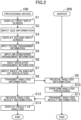
- FIG. 2 is a flowchart showing the operation of the visualization system (1).
- FIG. 3 is a plan view of the target area (E).
- the operator shows up to the target area (E) to check the air conditions in the target area (E).
- the operator operates the processing device (100) to start an operation for visualizing the air conditions in the target area (E).
- a step S1 after the start of the operation, the display (110) of the processing device (100) displays a first input screen (g1).
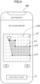
- the first input screen (g1) is for inputting floor surface information on the target area (E).
- FIG. 4 shows the first input screen (g1).
- the receiver (120) of the processing device (100) receives an input of the size information on the size of the target area (E).
- the size information includes floor surface information indicating the size of the floor surface of the target area (E) and height information indicating the height from the floor surface to the ceiling of the target area (E).
- the operator inputs the floor surface information from the first input screen (g1).
- the first input screen (g1) displays a floor surface setting image (e1) for setting the size of the floor surface.
- the operator performs a drag-and-drop operation at a corner (e11) of the floor surface setting image (e1) and a shape change of the floor surface setting image (e1) on the input screen (g1) to approximate to a scale drawing of the floor surface (F) of the actual target area (E).
- the image obtained by the shape change of the floor surface setting image (e1) may be referred to as a "target area image" (e) (see FIG. 5 ).
- the target area image (e) is in a shape approximate to the scale drawing of the floor surface (F) of the actual target area (E). With the target area image (e) formed through the shape change of the floor surface setting image (e1), the input operation of the floor surface information on the target area (E) is completed.
- the operator After the formation of the target area image (e), the operator performs the touch operation on the icon (v1) on the input screen (g1).
- the touch operation on the icon (v1) causes the display of an input screen (not shown) for inputting the height information on the target area (E).
- the operator inputs a numerical value indicating the height of the target area (E) through the touch operation on a number icon displayed on the input screen for inputting the height information.
- the numerical value indicating the height of the target area (E) may be input using a range slider for inputting a numerical value.
- the display (110) displays a second input screen (g2).
- the second input screen (g2) is for inputting arrangement information indicating the locations of object images on the target area image (e).
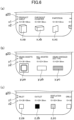
- the object images include fixture images (x) showing fixtures (X) (see FIG. 6A ), air conditioner images (y) showing air conditioners (Y) (see FIG. 6B ), and ventilator images (z) showing ventilators (Z) (see FIG. 6C ).
- the top (g21) of the second input screen (g2) displays a plurality of types of icons (v) for selecting the type of an object.
- the plurality of types of icons (v) include an icon (v2) "FIXTURE", an icon (v3) “AIR CONDITIONER”, and an icon (v4) "VENTILATOR”.
- the vertical center (g22) of the second input screen (g2) displays the target area image (e) formed in the step S2.
- the bottom (g23) of the second input screen (g2) displays images of the objects corresponding to the icon selected from the plurality of types of icons (v2, v3, and v4) displayed at the top (g21).
- the receiver (120) of the processing device (100) receives an input of fixture arrangement information.
- the fixture arrangement information indicates the locations of the fixture images (x) on the target area image (e).
- the fixture arrangement information is a first example of the "arrangement information" according to the present disclosure.
- the operator performs the touch operation on the icon (v2) indicating the fixtures (X) among the icons (v2) to (v4) at the top (g21) of the second input screen (g2). Accordingly, the bottom (g23) of the second input screen (g2) displays a plurality of types of fixture images (x).
- a horizontal flick operation of the bottom (g23) of the second input screen (g2) allows the slide of a fixture image (x) currently displayed at the bottom (g23) and the appearance of different types of fixture images (x) at the bottom (g23).
- the bottom (g23) of the second input screen (g2) displays the plurality of types of fixture images (x), a plurality of types of fixture names (x1), and a plurality of types of fixture dimensions (x2) in association with each other.
- the fixture names (x1) are the names of the fixtures (X) shown by the associated fixture images (x). Through visual check of the fixture names (x1), the operator can easily specify the types of the fixtures (X) shown by the associated fixture images (x).
- the fixture dimensions (x2) are the dimensions of the fixtures (X) shown by the associated fixture images (x).
- the fixture dimensions (x2) are set to default values. Note that the fixture dimensions (x2) may be changeable from the default values by the receiver (120).
- the operator inputs the fixture arrangement information as follows.
- the operator performs a drag-and-drop operation on a fixture image (x) showing a fixture (X) to be placed on the target area (E) among the plurality of types of fixture images (x) displayed at the bottom (g23) of the second input screen (g2) and moving and placing the fixture image (x) on the target area image (e).
- the operator places the fixture image (x) on the target area image (e) to match the location of the fixture (X) in the actual target area (E).
- the fixture arrangement information on all the fixtures (X) is input on the target area image (e) on the target area (E).
- the process proceeds to a step S5.
- the receiver (120) of the processing device (100) receives an input of air conditioner arrangement information.
- the air conditioner arrangement information indicates the locations of the air conditioner images (y) on the target area image (e).
- the air conditioner arrangement information is a second example of the "arrangement information" according to the present disclosure.
- the operator performs the touch operation on the icon (v3) indicating air conditioners (Y) among the icons (v2) to (v4) at the top (g21) of the second input screen (g2). Accordingly, the bottom (g23) of the second input screen (g2) displays a plurality of types of air conditioner images (y).
- the bottom (g23) of the second input screen (g2) displays the plurality of types of air conditioner images (y), a plurality of types of air conditioner names (y1), and a plurality of types of air conditioner dimensions (y2) in association with each other.
- the air conditioner names (y1) are the names of the air conditioners (Y) shown by the associated air conditioner images (y). Through visual check of the air conditioner names (y1), the operator can easily specify the types of the air conditioners (Y) shown by the associated air conditioner images (y).
- the air conditioner dimensions (y2) are the dimensions of the air conditioners (Y) shown by the associated air conditioner images (y).
- the air conditioner dimensions (y2) are set to default values. Note that the air conditioner dimensions (y2) may be changeable from the default values by the receiver (120).
- the operator inputs the air conditioner arrangement information as follows.
- the operator performs a drag-and-drop operation on an air conditioner image (y) showing an air conditioner (Y) to be placed on the target area (E) among the plurality of types of air conditioner images (y) displayed at the bottom (g23) of the second input screen (g2) and moving and placing the air conditioner image (y) on the target area image (e).
- the operator places the air conditioner image (y) on the target area image (e) to match the location of the air conditioner (Y) in the actual target area (E).
- the air conditioner arrangement information is input on the target area image (e) for all the air conditioners (Y) on the target area (E). As a result, the process proceeds to a step S6.
- the receiver (120) of the processing device (100) receives an input of third arrangement information.
- the third arrangement information indicates the locations of the ventilator images (z) on the target area image (e).
- the ventilator arrangement information is a third example of the "arrangement information" according to the present disclosure.
- the operator performs the touch operation on the icon (v4) indicating ventilators (Z) among the icons (v2) to (v4) at the top (g21) of the second input screen (g2). Accordingly, the bottom (g23) of the second input screen (g2) displays a plurality of types of ventilator images (z).
- the bottom (g23) of the second input screen (g2) displays the plurality of types of ventilator images (z), a plurality of types of ventilator names (z1), and a plurality of types of ventilator dimensions (z2) in association with each other.
- the ventilator names (z1) are the names of the ventilators (Z) shown by the associated ventilator images (z). Through visual check of the ventilator names (z1), the operator can easily specify the types of the ventilators (Z) shown by the associated ventilator images (z).
- the ventilator dimensions (z2) are the dimensions of the ventilators (Z) shown by the associated ventilator images (z).
- the ventilator dimensions (z2) are set to default values. Note that the ventilator dimensions (z2) may be changeable from the default values by the receiver (120).
- the operator inputs the ventilator arrangement information as follows.
- the operator performs a drag-and-drop operation on a ventilator image (z) showing a ventilator (Z) to be placed on the target area (E) among the plurality of types of ventilator images (z) displayed at the bottom (g23) of the second input screen (g2) and moving and placing the ventilator image (z) on the target area image (e).
- the operator places the ventilator image (z) on the target area image (e) to match the location of the ventilator (Z) in the actual target area (E).
- the ventilator arrangement information is input on the target area image (e) for all the ventilators (Z) in the target area (E).
- FIG. 7 shows the second input screen (g2) under the following conditions after the end of the processing in the steps S4 to S6.
- the object images i.e., the fixture images (x), the air conditioner images (y), and the ventilator images (z)
- the target area image (e) to match the locations of the objects (i.e., the fixtures (X), the air conditioners (Y), and the ventilators (Z)) in the actual target area (E) (see FIG. 3 ).
- step S6 After the end of the processing shown in the step S6, the process proceeds to a step S7.
- the receiver (120) of the processing device (100) receives an input of an index on the amount of ventilation by ventilators (Z).
- the index on the amount of ventilation by the ventilators (Z) is related to the amount of ventilation by the ventilators (Z) shown by the ventilator images (z) for which the ventilator arrangement information is set in the step S6.
- the index on the amount of ventilation by each ventilator (Z) includes information indicating the air volume of the ventilator (Z), information indicating the number of times of ventilation by the ventilator (Z) (e.g., the number of times of ventilation per unit time), or information indicating the expected number of people present in the target area (E).
- the amount of ventilation indicates the volume of air in the target area (E) to be replaced per unit time.
- step S8 the processing proceeds to a step S8.
- the process does not necessarily proceed in the order of the steps S4, S5, S6, and S7 as in this embodiment and the order is not limited.
- the first communicator (130) of the processing device (100) transmits analysis information to the server (200).
- the analysis information includes the size information on the target area (E) received by the receiver (120) in the step S2, the fixture arrangement information, the air conditioner arrangement information, and the ventilator arrangement information received by the receiver (120) in the steps S4 to S6, and the index on the amount of ventilation by a ventilator (Z) received by the receiver (120) in the step S7.
- the second communicator (210) of the server (200) receives the analysis information from the processing device (100).
- the second controller (230) of the server (200) performs analysis processing based on the analysis information.
- the analysis processing is analyzing the air conditions in the target area (E).
- the second storage (220) of the server (200) stores various information for the analysis processing.
- the various information stored in the second storage (220) include first correspondence information (221), second correspondence information (222), and third correspondence information (223).
- the first correspondence information (221) indicates each fixture image (x) and effect information in association with each other.
- the effect information is the information on the effects of the fixture (X) shown by the fixture image (x) on the air conditions.
- the "information on the effects of the fixture (X) shown by the fixture image (x) on the air conditions” may be referred to as "fixture effect information”.
- the fixture effect information includes, for example, information indicating the influence of the fixture (X) on the airflow generated by the air conditioner (Y) or any other equipment (e.g., information on how the fixture (X) changes the airflow).
- the first correspondence information (221) is set for each of the plurality of types of fixture images (x) (e.g., a first fixture image (xa) showing the product shelf (XA), a second fixture image (xb) showing the checkout counter (XB), a third fixture image (xc) showing a partition) (see (a) of FIG. 6 ).
- x e.g., a first fixture image (xa) showing the product shelf (XA), a second fixture image (xb) showing the checkout counter (XB), a third fixture image (xc) showing a partition
- the second controller (230) of the server (200) outputs the fixture effect information for all the fixture images (x) arranged on the target area image (e) in the step S4.
- the second correspondence information (222) indicates each air conditioner image (y) and effect information in association with each other.
- the effect information is the information on the effects of the air conditioner (Y) shown by the air conditioner image (y) on the air conditions.
- the "information on the effects of the air conditioner (Y) shown by the air conditioner image (y) on the air conditions" may be referred to as "air conditioner effect information”.
- the air conditioner effect information includes, for example, information indicating the air-blowing direction of the air conditioner (Y).
- the second controller (230) of the server (200) outputs the air conditioner effect information for all the air conditioner images (y) arranged on the target area image (e) in the step S5.
- the air conditioner effect information according to the second correspondence information (222) includes a first table, a second table, and a third table.
- the first table shows size information indicating the size (cm3) of the target area (E) and an air conditioning load (a cooling and heating load) (kW/cm3) in association with each other.
- the second table shows an air conditioning load and the required air conditioning capacity (kW) in association with each other.
- the third table shows the air conditioning capacity and the air volume of the air conditioner (Y) in association with each other.
- the second controller (230) of the server (200) outputs the air volume of the air conditioner (Y) based on the information on the size of the target area (E) received by the receiver (120) in the step S2.
- the second controller (230) of the server (200) first outputs the air conditioning load corresponding to the size of the target area (E) using the size information on the target area (E) and the first table, outputs the air conditioning capacity using the output air conditioning load and the second table, and then outputs the air volume of the air conditioner (Y) using the output air conditioning capacity and the third table.
- the air volume of each air conditioner (Y) is set to, for example, the value obtained by equally dividing the air volume output based on the size information on the target area (E) as described above.
- the air volume set for each air conditioner (Y) may be collectively referred to as "air conditioner air volume information".
- the second correspondence information (222) is set for each of the plurality of types of air conditioner images (y) (e.g., a first air conditioner image (ya) showing a ceiling cassette air conditioner (YA), a second air conditioner image (yb) showing a wall-mounted air conditioner, and a third air conditioner image (yc) showing a ceiling concealed duct air conditioner) (see FIG. 6B ).
- y e.g., a first air conditioner image (ya) showing a ceiling cassette air conditioner (YA), a second air conditioner image (yb) showing a wall-mounted air conditioner, and a third air conditioner image (yc) showing a ceiling concealed duct air conditioner
- the third correspondence information (223) indicates each ventilator image (z) and effect information in association with each other.
- the effect information is the information on the effects of the ventilator (Z) shown by the ventilator image (z) on the air conditions.
- the "information on the effects of the ventilator (Z) shown by the ventilator image (z) on the air conditions" may be referred to as "ventilator effect information”.
- the ventilator effect information includes, for example, information indicating the air blowing direction of the ventilator (Z) (e.g., the outlet (ZB) or a ventilation fan), information indicating the air intake direction of the ventilator (Z) (e.g., the air inlet (ZA)).
- the second controller (230) of the server (200) outputs the ventilator effect information for all the ventilator images (z) arranged on the target area image (e) in the step S6.
- the ventilator effect information according to the third correspondence information (223) includes a fourth table.
- the fourth table indicates the amount of ventilation and an index in association with each other.
- the second controller (230) of the server (200) uses the fourth table to output the amount of ventilation associated with the index (see the step S7) received by the receiver (120) and outputs the amount of ventilation as the amount of ventilation by the ventilator (Z) in the target area (E).
- the amount of ventilation output using the fourth table and the index (see the step S7) of the amount of ventilation received by the receiver (120) may be referred to as "ventilation amount information".
- the third correspondence information (223) is set for each of the plurality of types of ventilator images (z) (e.g., a first ventilator image (za) showing the air inlet (ZA), a second ventilator image (zb) showing the air outlet (ZB), a third ventilator image (zc) showing the ventilation fan) (see FIG. 6C ).
- the second controller (230) of the server (200) inputs the following information as parameters to a predetermined program (e.g., dedicated or general-purpose fluid analysis software) for fluid analysis simulation to output the result of analysis of the air conditions in the target area (E).
- the information includes the fixture arrangement information (see the step S4), the fixture effect information, the air conditioner arrangement information (see the step S5), the air conditioner effect information, the air conditioner air volume information, the ventilator arrangement information (see the step S6), the ventilator effect information, and the ventilation amount information.
- the predetermined program is stored in the second storage (220) of the server (200).
- output as a result of analysis is information indicating the age of the air in the target area (E).
- the age of the air indicates the time required for the air entering the target area (E) to reach a predetermined point in the target area (E). Younger air represents fresher air.
- the second communicator (210) of the server (200) transmits information indicating a result of analysis to the processing device (100).
- the first communicator (130) of the processing device (100) receives the information indicating the result of analysis from the server (200).
- the display (110) of the processing device (100) displays an analysis result display screen (g3).
- the analysis result display screen (g3) includes a first screen (g31) and a second screen (g32).
- the first screen (g31) displays the target area image (e) shown in FIG. 7 , that is, an image with the same content as the image used by the server (200) for the analysis processing.
- the second screen (g32) displays information indicating the result of analysis of the air conditions in the target area (E) by the server (200).
- the second screen (g32) displays information on the age of the air in the target area (E).
- the second screen (g32) is displayed below the first screen (g31).
- the second screen (g32) displays the information indicating the result of analysis to overlap each other.
- the second screen (g32) displays the information indicating the result of analysis in the form of a contour diagram representing older and more stagnant air in a darker color.
- the bottom right area (e1) of the target area image (e) is darker in color and thus contains older and more stagnant air.
- the second storage (220) stores the correspondence information (the first to third correspondence information (221) to (223)) indicating the object images (the fixture images (x), the air conditioner images (y), and the ventilator images (z)) and the information on the effects of the objects (the fixtures (X), the air conditioners (Y), and the ventilators (Z)) shown by the object images on the air conditions in association with each other.
- the second controller (230) outputs information indicating the air conditions in the target area (E) based on the arrangement information on the object images (e.g., the fixture arrangement information, the air conditioner arrangement information, and the ventilator arrangement information) and the correspondence information.
- the correspondence information stored in the second storage (220) indicates the object images and the information on the effects of the objects shown by the object images on the air conditions in association with each other. There is thus no need for an operator to check and input the information on the effects of the objects on the air conditions in the target area (E) into the processing device (100) to output the air conditions in the target area (E). This reduces the burden on the operator and allows the operator to easily check the air conditions in the target area (E).
- the information on the effects of the air conditioner (Y) on the air conditions includes information (i.e., the second table) on the air conditioning capacity of the air conditioner (Y). In this configuration, the information on the effects stored in the second storage (220) includes the information on the air conditioning capacity of the air conditioner (Y).
- the second controller (230) can calculate the air volume of the air conditioner (Y) from the size of the target area (E) and the air conditioning capacity and use the air volume as a parameter for outputting the air conditions in the target area (E). This eliminates the need for an operator to input the air conditioning capacity, the air volume of the air conditioner (Y), or other data to output the air conditions in the target area (E) and increases the range of calculation for outputting analysis information by the second controller (230). This reduces the burden on the operator and allows the operator to easily check the air conditions in the target area (E).
- the operator can carry the processing device (100), which is a smartphone, to the target area (E).
- the operator performs the data input operation shown in the steps S2 to S6 and transmit, to the server (200), information indicating the result of input.
- the operator can obtain information indicating a result of analysis from the server (200) using the processing device (100) and check the information indicating the result of analysis on the display (110) of the processing device (100). As a result, the operator can quickly obtain the air conditions in the target area (E).
- the air condition includes a plurality of conditions.
- the plurality of conditions correspond to a plurality of colors different from each other.
- the display (110) displays the plurality of conditions in distribution points of the target area (E) in the corresponding colors.
- the second screen (g32) of the display (110) displays older air in a darker color for each distribution point of the target area (E).
- the present disclosure is useful as a visualization system and a program.
Landscapes
- Engineering & Computer Science (AREA)
- Physics & Mathematics (AREA)
- Theoretical Computer Science (AREA)
- General Engineering & Computer Science (AREA)
- General Physics & Mathematics (AREA)
- Geometry (AREA)
- Evolutionary Computation (AREA)
- Mechanical Engineering (AREA)
- Combustion & Propulsion (AREA)
- Chemical & Material Sciences (AREA)
- Computer Hardware Design (AREA)
- Human Computer Interaction (AREA)
- Mathematical Analysis (AREA)
- Pure & Applied Mathematics (AREA)
- Mathematical Optimization (AREA)
- Signal Processing (AREA)
- Multimedia (AREA)
- Software Systems (AREA)
- Medical Informatics (AREA)
- Computer Vision & Pattern Recognition (AREA)
- Mathematical Physics (AREA)
- Computing Systems (AREA)
- Artificial Intelligence (AREA)
- Architecture (AREA)
- Computational Mathematics (AREA)
- Fuzzy Systems (AREA)
- General Health & Medical Sciences (AREA)
- Databases & Information Systems (AREA)
- Health & Medical Sciences (AREA)
- Automation & Control Theory (AREA)
- Algebra (AREA)
- Fluid Mechanics (AREA)
- Civil Engineering (AREA)
- Structural Engineering (AREA)
- Air Conditioning Control Device (AREA)
- Management, Administration, Business Operations System, And Electronic Commerce (AREA)
Applications Claiming Priority (2)
| Application Number | Priority Date | Filing Date | Title |
|---|---|---|---|
| JP2021060830 | 2021-03-31 | ||
| PCT/JP2022/014936 WO2022210516A1 (fr) | 2021-03-31 | 2022-03-28 | Système de visualisation et programme |
Publications (3)
| Publication Number | Publication Date |
|---|---|
| EP4318295A1 true EP4318295A1 (fr) | 2024-02-07 |
| EP4318295A4 EP4318295A4 (fr) | 2024-10-02 |
| EP4318295B1 EP4318295B1 (fr) | 2025-08-13 |
Family
ID=83456329
Family Applications (1)
| Application Number | Title | Priority Date | Filing Date |
|---|---|---|---|
| EP22780727.8A Active EP4318295B1 (fr) | 2021-03-31 | 2022-03-28 | Système de visualisation et programme |
Country Status (5)
| Country | Link |
|---|---|
| US (1) | US12025330B2 (fr) |
| EP (1) | EP4318295B1 (fr) |
| JP (1) | JP7161138B2 (fr) |
| CN (1) | CN117063192B (fr) |
| WO (1) | WO2022210516A1 (fr) |
Families Citing this family (2)
| Publication number | Priority date | Publication date | Assignee | Title |
|---|---|---|---|---|
| JP2024120688A (ja) * | 2023-02-24 | 2024-09-05 | パナソニックIpマネジメント株式会社 | 熱流体解析システム及び熱流体解析方法 |
| JP2025146295A (ja) * | 2024-03-22 | 2025-10-03 | ダイキン工業株式会社 | 環境推定装置、表示システム、空気調和システム、環境推定方法、プログラム、環境推定システム、および学習済みモデルの製造方法 |
Family Cites Families (29)
| Publication number | Priority date | Publication date | Assignee | Title |
|---|---|---|---|---|
| JP2001344294A (ja) | 2000-06-01 | 2001-12-14 | Shimizu Corp | 建物内の伝熱・空気流動設計支援システム |
| JP2002032701A (ja) | 2000-07-14 | 2002-01-31 | Kajima Corp | 建築物の性能解析方法及び装置 |
| JP4151780B2 (ja) * | 2002-09-09 | 2008-09-17 | 財団法人生産技術研究奨励会 | 空気齢分布性状解析システム及び空気余命分布性状解析システム |
| JP3803103B2 (ja) * | 2004-05-21 | 2006-08-02 | シャープ株式会社 | イオン濃度分布の予測方法、解析装置およびイオン濃度分布の予測プログラム |
| JP4465331B2 (ja) * | 2006-05-17 | 2010-05-19 | 株式会社シーピーユー | 建築設計プログラム、これを格納した記録媒体、及び、このプログラムをインストールした建築cad装置 |
| WO2013038439A1 (fr) * | 2011-09-13 | 2013-03-21 | 三菱電機株式会社 | Dispositif de réfrigération et de climatisation |
| JP5836741B2 (ja) * | 2011-09-30 | 2015-12-24 | 日立アプライアンス株式会社 | 空調制御端末および空調制御の設定操作方法 |
| WO2014128777A1 (fr) * | 2013-02-20 | 2014-08-28 | パナソニック インテレクチュアル プロパティ コーポレーション オブ アメリカ | Programme et procédé pour commander un terminal d'informations portatif |
| JP6359417B2 (ja) * | 2014-10-21 | 2018-07-18 | アズビル株式会社 | 温度分布表示装置および方法 |
| KR20160097701A (ko) * | 2015-02-09 | 2016-08-18 | 엘지전자 주식회사 | 공기조화기 |
| CN106016583B (zh) * | 2016-05-17 | 2018-12-07 | 珠海格力电器股份有限公司 | 空调系统的控制方法及控制装置、空调系统 |
| KR102393418B1 (ko) * | 2017-03-30 | 2022-05-03 | 삼성전자주식회사 | 데이터 학습 서버 및 이의 학습 모델 생성 및 이용 방법 |
| JP6685467B2 (ja) * | 2017-03-31 | 2020-04-22 | 三菱電機株式会社 | 制御機器及び空調システム |
| CN108050676B (zh) * | 2017-10-30 | 2019-12-10 | 珠海格力电器股份有限公司 | 空调及其控制方法、装置和系统 |
| CN111954784A (zh) * | 2018-02-26 | 2020-11-17 | 美的集团股份有限公司 | 一种用于进行空气调节的方法和系统 |
| US11118804B2 (en) * | 2018-03-16 | 2021-09-14 | Delta Controls Inc. | Building automation system and method using ceiling-mounted infrared sensors |
| KR102443052B1 (ko) * | 2018-04-13 | 2022-09-14 | 삼성전자주식회사 | 공기 조화기 및 공기 조화기의 제어 방법 |
| KR101941921B1 (ko) * | 2018-05-28 | 2019-01-25 | 한국과학기술정보연구원 | 오염물질 대류-확산 경향 해석시스템 및 오염물질 대류-확산 경향 해석 방법 |
| CN111174379B (zh) * | 2018-10-24 | 2022-01-21 | 重庆海尔空调器有限公司 | 空调集群的控制方法、装置、空调集群及智能家居系统 |
| JP7325444B2 (ja) * | 2018-12-13 | 2023-08-14 | 三菱電機株式会社 | 省エネ管理装置、省エネ管理方法及びプログラム |
| JP7190661B2 (ja) * | 2019-02-06 | 2022-12-16 | パナソニックIpマネジメント株式会社 | 画像処理装置、画像処理方法および画像処理システム |
| JPWO2020184077A1 (fr) * | 2019-03-12 | 2020-09-17 | ||
| JP7280149B2 (ja) * | 2019-08-26 | 2023-05-23 | 旭化成ホームズ株式会社 | 住環境シミュレーションシステム、住環境シミュレーション方法およびプログラム |
| CN110736244B (zh) * | 2019-10-29 | 2020-10-20 | 珠海格力电器股份有限公司 | 控制空调的方法、装置和空调 |
| CN110986287B (zh) * | 2019-10-31 | 2021-01-22 | 珠海格力电器股份有限公司 | 一种空调控制方法、装置、存储介质及空调 |
| US20230134914A1 (en) * | 2020-03-11 | 2023-05-04 | Panasonic Intellectual Property Management Co., Ltd. | Signal processing system, sensor system, biometric management system, environmental control system, signal processing method, and program |
| CN111649433A (zh) * | 2020-06-03 | 2020-09-11 | 合肥学院 | 一种有效的降低室内甲醛浓度的方法 |
| CN112149364B (zh) * | 2020-09-04 | 2022-11-29 | 同济大学 | 一种智慧人居环境气流组织优化方法 |
| US12372263B2 (en) * | 2021-03-29 | 2025-07-29 | Johnson, Levinson, Ragan, Davila, Inc. | System and method for the mitigation of risk of exposure to contaminants and providing information thereof |
-
2022
- 2022-03-28 WO PCT/JP2022/014936 patent/WO2022210516A1/fr not_active Ceased
- 2022-03-28 CN CN202280024639.6A patent/CN117063192B/zh active Active
- 2022-03-28 EP EP22780727.8A patent/EP4318295B1/fr active Active
- 2022-03-28 JP JP2022051252A patent/JP7161138B2/ja active Active
-
2023
- 2023-09-28 US US18/374,130 patent/US12025330B2/en active Active
Also Published As
| Publication number | Publication date |
|---|---|
| EP4318295B1 (fr) | 2025-08-13 |
| CN117063192B (zh) | 2024-09-10 |
| US20240019152A1 (en) | 2024-01-18 |
| WO2022210516A1 (fr) | 2022-10-06 |
| JP7161138B2 (ja) | 2022-10-26 |
| CN117063192A (zh) | 2023-11-14 |
| EP4318295A4 (fr) | 2024-10-02 |
| US12025330B2 (en) | 2024-07-02 |
| JP2022159090A (ja) | 2022-10-17 |
Similar Documents
| Publication | Publication Date | Title |
|---|---|---|
| US12025330B2 (en) | Visualization system for target area of air conditioner | |
| EP4024258A1 (fr) | Analyse de la propagation des contaminants | |
| EP4132139B1 (fr) | Système de climatisation | |
| EP3457042A1 (fr) | Système de visualisation de climatisation | |
| WO2012101762A1 (fr) | Dispositif de commande, procédé de commande et programme associé | |
| CN103097827A (zh) | 空气调节系统以及空气调节方法 | |
| JP2019067083A (ja) | 換気設計装置、換気設計方法、該方法を実行するためのプログラム及び記憶媒体 | |
| WO2007122677A1 (fr) | PROCEDE de support de conception de champ de diffusion de substance/champ de convection thermique, système de support de conception et programme de support de conception | |
| EP4083844A1 (fr) | Dispositif de traitement d'informations, système de traitement d'informations et procédé de traitement d'informations | |
| EP4336114A1 (fr) | Dispositif de commande de climatisation | |
| JPH10187785A (ja) | ダクト空調システムの設計支援装置および方法 | |
| JP2023056108A (ja) | 空調気流予測装置及び空調気流予測方法 | |
| JP2007310528A (ja) | 建築設計プログラム、これを格納した記録媒体、及び、このプログラムをインストールした建築cad装置 | |
| CN103574856B (zh) | 空调控制解显示装置及方法 | |
| US20140200935A1 (en) | Product Value Dynamic Lab Test Equipment Control, Data Analyzer and Method | |
| JP7308902B2 (ja) | 気流シミュレーション端末装置、及び気流シミュレーション方法 | |
| KR102735675B1 (ko) | 공기 청정기의 시뮬레이션 방법 | |
| CN119677999B (zh) | 设计方法、程序和设计系统 | |
| US20240263822A1 (en) | Display method, terminal device, display system, and storage medium | |
| JP7471350B2 (ja) | 端末装置の制御方法、端末装置、プログラム、及び表示システム | |
| JP2024165129A (ja) | 配置出力装置、配置出力装置の出力方法及びプログラム | |
| JP2021081168A (ja) | 環境を調整する設備機器を操作するためのプログラム、設備機器操作方法、及び設備機器操作システム | |
| JP2000132586A (ja) | 天井吹出し口選定装置 | |
| JP2017134128A (ja) | リコールマップ作成システム | |
| WO2025197366A1 (fr) | Dispositif d'estimation d'environnement, système d'affichage, système de climatisation, procédé d'estimation d'environnement, programme, système d'estimation d'environnement et procédé de fabrication de modèle entraîné |
Legal Events
| Date | Code | Title | Description |
|---|---|---|---|
| STAA | Information on the status of an ep patent application or granted ep patent |
Free format text: STATUS: THE INTERNATIONAL PUBLICATION HAS BEEN MADE |
|
| PUAI | Public reference made under article 153(3) epc to a published international application that has entered the european phase |
Free format text: ORIGINAL CODE: 0009012 |
|
| STAA | Information on the status of an ep patent application or granted ep patent |
Free format text: STATUS: REQUEST FOR EXAMINATION WAS MADE |
|
| 17P | Request for examination filed |
Effective date: 20231030 |
|
| AK | Designated contracting states |
Kind code of ref document: A1 Designated state(s): AL AT BE BG CH CY CZ DE DK EE ES FI FR GB GR HR HU IE IS IT LI LT LU LV MC MK MT NL NO PL PT RO RS SE SI SK SM TR |
|
| DAV | Request for validation of the european patent (deleted) | ||
| DAX | Request for extension of the european patent (deleted) | ||
| P01 | Opt-out of the competence of the unified patent court (upc) registered |
Free format text: CASE NUMBER: APP_38437/2024 Effective date: 20240627 |
|
| A4 | Supplementary search report drawn up and despatched |
Effective date: 20240903 |
|
| RIC1 | Information provided on ipc code assigned before grant |
Ipc: G05B 15/02 20060101ALI20240828BHEP Ipc: G06Q 10/10 20230101ALI20240828BHEP Ipc: G06F 30/27 20200101ALI20240828BHEP Ipc: G06F 30/12 20200101AFI20240828BHEP |
|
| GRAP | Despatch of communication of intention to grant a patent |
Free format text: ORIGINAL CODE: EPIDOSNIGR1 |
|
| STAA | Information on the status of an ep patent application or granted ep patent |
Free format text: STATUS: GRANT OF PATENT IS INTENDED |
|
| RIC1 | Information provided on ipc code assigned before grant |
Ipc: G05B 15/02 20060101ALI20250416BHEP Ipc: G06Q 10/10 20230101ALI20250416BHEP Ipc: G06F 30/27 20200101ALI20250416BHEP Ipc: G06F 30/12 20200101AFI20250416BHEP |
|
| INTG | Intention to grant announced |
Effective date: 20250430 |
|
| GRAS | Grant fee paid |
Free format text: ORIGINAL CODE: EPIDOSNIGR3 |
|
| GRAA | (expected) grant |
Free format text: ORIGINAL CODE: 0009210 |
|
| STAA | Information on the status of an ep patent application or granted ep patent |
Free format text: STATUS: THE PATENT HAS BEEN GRANTED |
|
| AK | Designated contracting states |
Kind code of ref document: B1 Designated state(s): AL AT BE BG CH CY CZ DE DK EE ES FI FR GB GR HR HU IE IS IT LI LT LU LV MC MK MT NL NO PL PT RO RS SE SI SK SM TR |
|
| REG | Reference to a national code |
Ref country code: GB Ref legal event code: FG4D |
|
| REG | Reference to a national code |
Ref country code: CH Ref legal event code: EP |
|
| REG | Reference to a national code |
Ref country code: DE Ref legal event code: R096 Ref document number: 602022019495 Country of ref document: DE |
|
| REG | Reference to a national code |
Ref country code: IE Ref legal event code: FG4D |
|
| REG | Reference to a national code |
Ref country code: NL Ref legal event code: MP Effective date: 20250813 |
|
| PG25 | Lapsed in a contracting state [announced via postgrant information from national office to epo] |
Ref country code: IS Free format text: LAPSE BECAUSE OF FAILURE TO SUBMIT A TRANSLATION OF THE DESCRIPTION OR TO PAY THE FEE WITHIN THE PRESCRIBED TIME-LIMIT Effective date: 20251213 |
|
| PG25 | Lapsed in a contracting state [announced via postgrant information from national office to epo] |
Ref country code: NO Free format text: LAPSE BECAUSE OF FAILURE TO SUBMIT A TRANSLATION OF THE DESCRIPTION OR TO PAY THE FEE WITHIN THE PRESCRIBED TIME-LIMIT Effective date: 20251113 |
|
| REG | Reference to a national code |
Ref country code: LT Ref legal event code: MG9D |
|
| PG25 | Lapsed in a contracting state [announced via postgrant information from national office to epo] |
Ref country code: PT Free format text: LAPSE BECAUSE OF FAILURE TO SUBMIT A TRANSLATION OF THE DESCRIPTION OR TO PAY THE FEE WITHIN THE PRESCRIBED TIME-LIMIT Effective date: 20251215 |
|
| PG25 | Lapsed in a contracting state [announced via postgrant information from national office to epo] |
Ref country code: FI Free format text: LAPSE BECAUSE OF FAILURE TO SUBMIT A TRANSLATION OF THE DESCRIPTION OR TO PAY THE FEE WITHIN THE PRESCRIBED TIME-LIMIT Effective date: 20250813 |
|
| PG25 | Lapsed in a contracting state [announced via postgrant information from national office to epo] |
Ref country code: HR Free format text: LAPSE BECAUSE OF FAILURE TO SUBMIT A TRANSLATION OF THE DESCRIPTION OR TO PAY THE FEE WITHIN THE PRESCRIBED TIME-LIMIT Effective date: 20250813 Ref country code: NL Free format text: LAPSE BECAUSE OF FAILURE TO SUBMIT A TRANSLATION OF THE DESCRIPTION OR TO PAY THE FEE WITHIN THE PRESCRIBED TIME-LIMIT Effective date: 20250813 |
|
| PG25 | Lapsed in a contracting state [announced via postgrant information from national office to epo] |
Ref country code: GR Free format text: LAPSE BECAUSE OF FAILURE TO SUBMIT A TRANSLATION OF THE DESCRIPTION OR TO PAY THE FEE WITHIN THE PRESCRIBED TIME-LIMIT Effective date: 20251114 |
|
| PG25 | Lapsed in a contracting state [announced via postgrant information from national office to epo] |
Ref country code: SE Free format text: LAPSE BECAUSE OF FAILURE TO SUBMIT A TRANSLATION OF THE DESCRIPTION OR TO PAY THE FEE WITHIN THE PRESCRIBED TIME-LIMIT Effective date: 20250813 |
|
| PG25 | Lapsed in a contracting state [announced via postgrant information from national office to epo] |
Ref country code: LV Free format text: LAPSE BECAUSE OF FAILURE TO SUBMIT A TRANSLATION OF THE DESCRIPTION OR TO PAY THE FEE WITHIN THE PRESCRIBED TIME-LIMIT Effective date: 20250813 |
|
| PG25 | Lapsed in a contracting state [announced via postgrant information from national office to epo] |
Ref country code: BG Free format text: LAPSE BECAUSE OF FAILURE TO SUBMIT A TRANSLATION OF THE DESCRIPTION OR TO PAY THE FEE WITHIN THE PRESCRIBED TIME-LIMIT Effective date: 20250813 Ref country code: PL Free format text: LAPSE BECAUSE OF FAILURE TO SUBMIT A TRANSLATION OF THE DESCRIPTION OR TO PAY THE FEE WITHIN THE PRESCRIBED TIME-LIMIT Effective date: 20250813 |
|
| PG25 | Lapsed in a contracting state [announced via postgrant information from national office to epo] |
Ref country code: RS Free format text: LAPSE BECAUSE OF FAILURE TO SUBMIT A TRANSLATION OF THE DESCRIPTION OR TO PAY THE FEE WITHIN THE PRESCRIBED TIME-LIMIT Effective date: 20251113 |
|
| PG25 | Lapsed in a contracting state [announced via postgrant information from national office to epo] |
Ref country code: ES Free format text: LAPSE BECAUSE OF FAILURE TO SUBMIT A TRANSLATION OF THE DESCRIPTION OR TO PAY THE FEE WITHIN THE PRESCRIBED TIME-LIMIT Effective date: 20250813 |
|
| REG | Reference to a national code |
Ref country code: AT Ref legal event code: MK05 Ref document number: 1825471 Country of ref document: AT Kind code of ref document: T Effective date: 20250813 |
|
| PG25 | Lapsed in a contracting state [announced via postgrant information from national office to epo] |
Ref country code: SM Free format text: LAPSE BECAUSE OF FAILURE TO SUBMIT A TRANSLATION OF THE DESCRIPTION OR TO PAY THE FEE WITHIN THE PRESCRIBED TIME-LIMIT Effective date: 20250813 |
|
| PGFP | Annual fee paid to national office [announced via postgrant information from national office to epo] |
Ref country code: GB Payment date: 20260324 Year of fee payment: 5 |
|
| PG25 | Lapsed in a contracting state [announced via postgrant information from national office to epo] |
Ref country code: DK Free format text: LAPSE BECAUSE OF FAILURE TO SUBMIT A TRANSLATION OF THE DESCRIPTION OR TO PAY THE FEE WITHIN THE PRESCRIBED TIME-LIMIT Effective date: 20250813 |
|
| PGFP | Annual fee paid to national office [announced via postgrant information from national office to epo] |
Ref country code: DE Payment date: 20260319 Year of fee payment: 5 |
|
| PG25 | Lapsed in a contracting state [announced via postgrant information from national office to epo] |
Ref country code: AT Free format text: LAPSE BECAUSE OF FAILURE TO SUBMIT A TRANSLATION OF THE DESCRIPTION OR TO PAY THE FEE WITHIN THE PRESCRIBED TIME-LIMIT Effective date: 20250813 |
|
| PG25 | Lapsed in a contracting state [announced via postgrant information from national office to epo] |
Ref country code: IT Free format text: LAPSE BECAUSE OF FAILURE TO SUBMIT A TRANSLATION OF THE DESCRIPTION OR TO PAY THE FEE WITHIN THE PRESCRIBED TIME-LIMIT Effective date: 20250813 |
|
| PGFP | Annual fee paid to national office [announced via postgrant information from national office to epo] |
Ref country code: FR Payment date: 20260323 Year of fee payment: 5 |
|
| PG25 | Lapsed in a contracting state [announced via postgrant information from national office to epo] |
Ref country code: CZ Free format text: LAPSE BECAUSE OF FAILURE TO SUBMIT A TRANSLATION OF THE DESCRIPTION OR TO PAY THE FEE WITHIN THE PRESCRIBED TIME-LIMIT Effective date: 20250813 |
|
| PG25 | Lapsed in a contracting state [announced via postgrant information from national office to epo] |
Ref country code: SK Free format text: LAPSE BECAUSE OF FAILURE TO SUBMIT A TRANSLATION OF THE DESCRIPTION OR TO PAY THE FEE WITHIN THE PRESCRIBED TIME-LIMIT Effective date: 20250813 Ref country code: EE Free format text: LAPSE BECAUSE OF FAILURE TO SUBMIT A TRANSLATION OF THE DESCRIPTION OR TO PAY THE FEE WITHIN THE PRESCRIBED TIME-LIMIT Effective date: 20250813 |