EP4319960B1 - Unité de tulipage, machine de tulipage automatique comprenant ladite unité et procédé de tulipage de tuyaux en pvc-o - Google Patents
Unité de tulipage, machine de tulipage automatique comprenant ladite unité et procédé de tulipage de tuyaux en pvc-o Download PDFInfo
- Publication number
- EP4319960B1 EP4319960B1 EP22714618.0A EP22714618A EP4319960B1 EP 4319960 B1 EP4319960 B1 EP 4319960B1 EP 22714618 A EP22714618 A EP 22714618A EP 4319960 B1 EP4319960 B1 EP 4319960B1
- Authority
- EP
- European Patent Office
- Prior art keywords
- pipe
- heating
- annular
- gasket
- contact element
- Prior art date
- Legal status (The legal status is an assumption and is not a legal conclusion. Google has not performed a legal analysis and makes no representation as to the accuracy of the status listed.)
- Active
Links
Images








Classifications
-
- B—PERFORMING OPERATIONS; TRANSPORTING
- B29—WORKING OF PLASTICS; WORKING OF SUBSTANCES IN A PLASTIC STATE IN GENERAL
- B29C—SHAPING OR JOINING OF PLASTICS; SHAPING OF MATERIAL IN A PLASTIC STATE, NOT OTHERWISE PROVIDED FOR; AFTER-TREATMENT OF THE SHAPED PRODUCTS, e.g. REPAIRING
- B29C57/00—Shaping of tube ends, e.g. flanging, belling or closing; Apparatus therefor, e.g. collapsible mandrels
- B29C57/02—Belling or enlarging, e.g. combined with forming a groove
- B29C57/04—Belling or enlarging, e.g. combined with forming a groove using mechanical means
-
- B—PERFORMING OPERATIONS; TRANSPORTING
- B29—WORKING OF PLASTICS; WORKING OF SUBSTANCES IN A PLASTIC STATE IN GENERAL
- B29C—SHAPING OR JOINING OF PLASTICS; SHAPING OF MATERIAL IN A PLASTIC STATE, NOT OTHERWISE PROVIDED FOR; AFTER-TREATMENT OF THE SHAPED PRODUCTS, e.g. REPAIRING
- B29C57/00—Shaping of tube ends, e.g. flanging, belling or closing; Apparatus therefor, e.g. collapsible mandrels
- B29C57/02—Belling or enlarging, e.g. combined with forming a groove
- B29C57/025—Belling or enlarging, e.g. combined with forming a groove combined with the introduction of a sealing ring, e.g. using the sealing element as forming element
Definitions
- This invention relates to a belling unit forming part of a belling machine for pipes made of thermoplastic material, that is to say, a unit designed to deform into the shape of a bell at least one end of a pipe made of thermoplastic material (as is known, a gasket is housed in the bell and the end of another pipe is inserted, in use, to form a conduit).
- the invention relates to a belling unit for thermoplastic pipes made of biaxially oriented PVC (polyvinyl chloride) (so-called PVC-O).
- PVC-O polyvinyl chloride
- PVC-O pipes are produced by means of an (artificial) stressing process which allows the orientation of the long molecular chains of PVC obtained from the extrusion process along a desired direction.
- the orientation in the longitudinal and circumferential directions obtained in the PVC-O allows the improvement of the physical properties with respect to the conventional PVC-U (rigid polyvinyl chloride).
- the temperature of the pipe is increased to a value greater than the vitreous transition temperature (Tg, approximately 75° - 80°C) of the PVC and a considerable force is then applied in the pipe both in an axial direction and in a circumferential direction (in such a way as to increase the diameter of the pipe and reduce its wall thickness).
- Tg vitreous transition temperature
- PVC-O pipes are pipes suitable for use with pressurised fluids (even with particularly high pressures).
- PVC-O pipes are, for the same nominal operating pressure of the pipe, made with a wall thickness less than the traditional PVC-U pipes (not oriented).
- PVC-O pipes may be used, with acceptable thicknesses, for particularly high pressures (up to 25 bar).
- a heated metal spindle known as pad
- pad is inserted in the end of the pipe heated beforehand (to a temperature greater than the vitreous transition temperature of the PVC) and on which a gasket has been placed, in a precise housing zone.
- the housing zone, formed in the pad, is suitably configured and sized according to the specific gasket to be housed.
- the end of the pipe fits the metal pad and the gasket.
- the pad and gasket together, constitute the mould for forming the bell.
- the gaskets used according to the Rieber system are different from the elastomeric gaskets designed, in general, to be inserted in the grooved seat of a traditional bell, that is to say, a bell shaped with a seat for the gasket to be inserted after forming and cooling the latter.
- the Rieber gaskets are characterised by a structure which includes in the elastomeric material a rigid annular part - made of metal or hard plastic - with specific gasket strengthening and stiffening functions.
- the Rieber system therefore makes it possible to make, with a single machine, a pipe provided with a bell complete with gasket, wherein the gasket is locked in the bell of the pipe.
- the method for belling PVC-O pipes currently finds an applicability limited to pipes for supplying pressurised fluids with thin thicknesses, for nominal operating pressures which are relatively low, not greater than 12.5 bar.
- the Applicant has carried out in-depth experimental studies aimed at analysing the problems of the belling method according to the RIEBER system which limited the application to pipes with a reduced wall thickness / diameter, designed to be used with relatively low nominal operating pressures.
- the numeral 100 denotes a belling machine designed to be installed in a plant for producing pipes T made of thermoplastic material.
- the machine 100 is able to make a bell at an end E of a pipe T incorporating a gasket G according to the RIEBER system.
- the machine 1 comprises a pre-heating unit 103, positioned upstream of the heating unit 101, and configured for heating the pipe T to a predetermined pre-heating temperature, which is lower than the heating temperature.
- the pipe T is positioned in the heating station after the pre-heating station. In this pre-heating station, the pipe T is heated to a temperature higher than the vitreous transition temperature of the PVC, and in any case higher than the pre-heating temperature.
- the pre-heating unit 103 comprises an oven.
- the oven is a contact oven.
- the invention relates to a unit 1 for belling pipes T made of thermoplastic material of the PVC-O type (forming part of the machine 100) comprising:
- Said annular heating element 12 is preferably made of metallic material (preferably an aluminium alloy).
- the electrical resistance(s) is/are configured for uniformly heating the annular heating element 12.
- the second heating device 5 heats, from the outside, preferably the end zone of the pipe T, from the end edge C of the pipe T up to the seat of the gasket G.
- the annular heating element 12 is configured for forming with the annular contact element 4, heated by the device 6, the hot chamber (cylindrical) 21.
- This hot chamber 21 is preferably sized to contain internally a portion of the end pipe T fitted on the annular contact element 4.
- the wall of the end zone of the pipe T is therefore contained in the hot chamber 21, with the relative inner surface in contact with the surface of the annular contact element 4 and with the adjacent outer surface detached from the inner surface of the annular heating element 12.
- the predetermined distance between the outer surface of the wall of the pipe T and the inner surface of the annular heating element 12 allows the insertion in the hot chamber 21 of the wall of the pipe without interference (without contact) with the annular heating element 12.
- the optimum distance between the wall of the pipe T and the inner surface of the annular heating element 12 is between 0.5 and 10 mm; more preferably between 1 and 8 mm; still more preferably, between 2 and 6 mm.
- the annular heating element 12 is positioned in such a way that the distance between the wall of the pipe T and the inner surface renders negligible the convective effects generated by the hot air, which would disturb the transmission of heat towards the pipe T.
- the transmission of heat from the annular heating element 12 to the pipe T occurs mainly by irradiation.
- the second heating device 5 heats the end zone of the pipe T in the absence of contact (the pipe is preferably positioned not in contact with the annular heating element 12).
- the second heating device 5 heats the end zone of the pipe T by irradiation.
- the unit 1 according to the invention is therefore able to process PVC-O pipes with large diameters / wall thicknesses.
- the forming pad 2 is equipped with a first annular seat S1 for housing at least a part of said gasket G.
- the annular contact element 4 is equipped with a second seat S2 for housing the gasket G, configured to house at least a part of said gasket G.
- the seats S1 and S2 are shaped for receiving respective portions of the gasket G.
- the seats S1 and S2 are shaped to allow the maximum adhesion between the gasket and, respectively, the forming pad 2 and the annular contact element 4.
- the technical effects determined by the presence of the second seat S2 for housing the gasket G and the first annular seat S1 for housing the gasket G are described below.
- the second seat S2 limits, in effect, the deformation of the gasket which occurs when the pipe T is fitted on it, receiving a part inside it.
- the second seat S2 has a concave shape towards the distal part of the pad 2 (that is, towards the clamp 10).
- the first annular housing seat S1 substantially has the same technical effect described above with regard to the second seat S2.
- the first annular housing seat S1 therefore contributes to the technical effect of limiting the deformation of the gasket G during the belling, receiving a part inside it, thereby reducing the risk of excessive deformation of the gasket.
- the unit 1 comprises a control and operating unit 7 (electronic, comprising hardware and/or software).
- the belling unit 1 comprises a first (temperature) sensor 9 configured for measuring the temperature at said first heating device 6 (more precisely for measuring the temperature of the annular contact element 4).
- the unit 1 comprises a second (temperature) sensor 8 configured for measuring the temperature at said second heating device 5.
- the first sensor 9 is a thermocouple.
- the second sensor 8 is a thermocouple.
- the control and operating unit 7 is configured for adjusting the second heating device 5 as a function of a temperature value measured by the second sensor 8, to perform a heating of a portion of the pipe T at the region 3 for housing said annular gasket G and extended up to the end edge C of the pipe T to a predetermined temperature.
- the control and operating unit 7 is configured for adjusting said first heating device 6 as a function of a temperature value measured by the first sensor 9, to perform a heating of the annular contact element 4 to a predetermined temperature (higher than the vitreous transition temperature).
- the apparatus 1 comprises a clamp 10 for clamping the pipe.
- Said clamp 10 is provided with clamping jaws (10A, 10B), movable relative to each other between a closed configuration and an open configuration (in particular, preferably, a first and a second jaw).
- the clamping clamp 10 constrains the pipe T in a horizontal position in such a way that the longitudinal axis X2 of the pipe T coincides with the axis X1 of the forming pad 2.
- the forming pad 2, the annular contact element 4 are supported by a carriage 11.
- the forming pad 2, the annular contact element 4, the second heater 5 and the first heater 6 are supported by the carriage 11 (movably relative to the frame of the machine).
- annular contact element 4 is configured to be able to move relative to the carriage 11, that is, relative to the forming pad 2.
- annular contact element 4 is supported by the carriage 11 with the possibility of movement independently of it.
- the annular contact element 4 and the second heater 5 are integral with each other (that is, always moved as one) in the movement with respect to the pad 2.
- the second heater 5 can be moved independently of the first heater 6 as it moves relative to the pad 2.
- This last embodiment offers the advantage of a greater adaptability to variations in the operating conditions; more specifically, when the annular contact element 4 withdraws and detaches from the pipe T the second heating device 5 may remain in the heating position, providing a heating contribution on the part of the pipe which under spontaneous contraction forms on the gasket and pad.
- the carriage 11 is configured to be movable between a position P4 close to the pipe T and a position P5 away from the pipe T.
- the carriage 11 is driven by respective actuator means (not illustrated).
- the annular contact element 4 is a hollow cylindrical body (preferably made of metal).
- the annular contact element 4 is mounted on the carriage 11 movably relative to the forming pad 2: in other words, the forming pad 2 and the annular contact element 4 are configured to be able to move independently.
- the annular contact element 4 is slidable on the forming pad 2; more precisely, the inner surface of the annular contact element 4 slides on the outer surface of the forming pad 2.
- the unit 1 may comprise means for picking up and moving the gasket G, not illustrated since it is of the conventional type.
- the housing region 3 is defined by a lowered zone formed on the outer surface of the pad 2.
- the gasket G preferably comprises an elastomeric portion G1 and a reinforced portion G2, made of a different material.
- the reinforced portion G2 is made of plastic or metallic material.
- the reinforced portion G2 is positioned, preferably, in the rear shoulder of the gasket.
- the reinforced portion G2 is embedded in the elastomeric portion G1 of the gasket G.
- the reinforced portion G2 preferably comprises a metal ring.
- the unit 1 comprises a heater configured for heating the forming pad 2.
- the pad 2 may be heated, according to a non-limiting example, by means of an internal circuit 13 for circulating a heating fluid (for example, water).
- a heating fluid for example, water
- the pad 2 is heated to temperatures of between 40°C and 65°C (below the vitreous transition temperature of PVC-O).
- the pad 2 is heated to a temperature of between 45°C and 60°C (or alternatively to temperatures of between 45°C and 55°C).
- annular contact element 4 is preferably heated (by the first heating device 6) to a temperature of between 85° and 105°C (more preferably between 90° and 100°C, even more preferably between 92°C and 100°C).
- the first heating device 6 is defined by electrical resistors 22.
- the electrical resistors 22 are controlled by the control and operating unit 7.
- the invention provides a method for belling pipes T made of thermoplastic material of the PVC-O type, comprising the following steps:
- the method also comprises the following steps:
- the annular contact element 4 is provided with a second seat S2 for housing a portion of the gasket G and the step of positioning said annular contact element 4 in the advanced position P1 comprises a step of receiving at least a portion of the gasket G inside the second housing seat S2.
- the forming pad 2 is provided with a first annular seat S1 for housing the gasket G, facing radially towards the outside of the pad 2, and the step of fitting said end portion E of the pipe T on the assembly of said pad 2 and said annular gasket G comprises a step of receiving at least a portion of the gasket G inside the first annular seat S1 of the forming pad 2.
- the step of preparing an annular gasket G on said forming pad 2 in a predetermined position comprises a step of fitting said gasket G on the forming pad 2 and moving the annular contact element 4 from the withdrawn position P2 to the advanced position P1 to make contact with the gasket G and move it to the predetermined position of said forming pad 2.
- the method before the step of moving, up to a predetermined distance, relative to each other said end portion E of the pipe T and the pad 2, the method comprises a step of clamping the pipe by closing a clamp 10.
- the method comprises a step of releasing the pipe T by opening the clamp 10 for a predetermined time, after the steps of:
- the step of releasing the pipe by opening the clamp 10 is carried out before, or partly superposing on, a step of moving said annular contact element 4 from the advanced position P1 to the withdrawn position P2, so as to release it from the gasket G and from the pipe T.
- the method comprises, after the step of releasing the pipe T by opening the clamp 10 for a predetermined time, a step of further clamping the pipe T by closing the clamp 10.
- the method comprises, after the step of moving said annular contact element 4 from the advanced position P1 to the withdrawn position P2, to release from the gasket G of the pipe T, a step of moving the annular contact element 4 from the withdrawn position P2 of disengagement towards the advanced position P1 of engagement, up to an intermediate position P3 of engagement of the annular contact element 4 with an end part of the pipe T between the gasket G and the end edge of the pipe T.
- this allows a bell B to be obtained wherein the gasket G has a desired final internal diameter, since the end of the pipe T is stressed by the annular element 4, when it is still in a malleable phase (not completely cooled), allowing the pipe T and seat of the gasket to be modelled so that, once the pipe T has cooled, the gasket G has the correct final diameter and can correctly receive the coupling of another pipe.
- the plastic behaviour is accentuated in the zone of the bell adjacent to the front shoulder of the gasket G up to the end edge of the bell.
- this zone has been subjected to the transmission of the heat of the hot chamber and, thanks also to this heating, has maintained a residual plasticity.
- the gasket G is compressed and flattened by the wall of the bell towards the pad 2.
- the gasket G is elastic; so, even if the inner wall of the bell in the zone of the gasket expands, the gasket G always maintains the adhesion to the inner wall of the bell, that is to say, it recovers elastically part of the previous flattening. Simultaneously, the progressive cooling of the wall of the bell of the pipe T continues, so that at the end of the contact action with the edge of the pipe T of the annular contact element 4, that is, when the annular contact element 4 is moved from the intermediate position P3 to the withdrawn position P2, the elastic relaxation of the gasket G is partly preserved, since the mechanical response of the part of the bell to the stress induced by the annular contact element 4 is not completely elastic, but elasto-plastic.
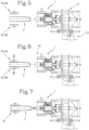
- Figures 5 to 23 show the steps of the belling cycle.
- Figure 5 illustrates the step of positioning the pipe T inside the clamp 10.
- the pipe T is positioned with its axis X2 aligned with (coinciding with) the axis X1 of the forming pad 2 (coinciding with the axis of the contact element 4).
- Figure 6 illustrates the step of closing the clamp 10.
- the pipe T is locked between the jaws 10A, 10B of the clamp 10.
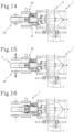
- Figures 7 to 14 illustrate the advancing of the carriage 11 towards the pipe T, in different advancing positions, respectively.
- the pipe T is progressively inserted on the forming pad 2 (the pipe is fitted on the forming pad 2, inserted in the gasket G and lastly in the annular contact element 4, that is to say, inserted in the hot chamber 21).
- the carriage 11 is moved from the far position P5 to the close position P4.
- Figure 15 illustrates a step wherein the carriage 11 is in the close position P4 and the annular contact element 4 in the advanced position P1.
- the clamp 10 is in the open configuration, that is, the respective jaws (10A, 10B) are open.
- the drawing shows the start of the step of extending the bell being formed, wherein the jaws 10A, 10B of the clamp 10 are kept open for a predetermined time.
- Figure 16 illustrates the continuation of the step of extending the bell.
- the clamp 10 is in the open configuration, the carriage 11 in the close position P4 and the annular contact element 4 starts the movement from the advanced position P1 towards the withdrawn position P2.
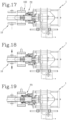
- the first heating device 6 is activated, for heating the inside of the pipe and, simultaneously, the second heating device 5 is activated, for heating from the outside the pipe T made of thermoplastic material.
- Both the heating devices (5, 6) contribute to heating the end zone of the pipe T which extends from the seat of the gasket G to the end edge C of the pipe T.
- Figure 18 illustrates the end of the step of extending the bell.
- the clamp 10 is in the closed configuration.
- Figure 19 illustrates the step wherein the annular contact element 4 is moved towards the pipe T (towards the advanced position P1), that is to say, it is moved to an intermediate position P3 (between the advanced position P1 and the withdrawn position P2) in which it engages with the edge of the bell of the pipe T.
- the annular contact element 4 is kept in this intermediate position for engaging with the edge of the pipe T for a predetermined time, to allow an elastic relaxation of the gasket G and the fitting of the edge of the pipe T.
- This step defines an elastic relaxation of the gasket G and the fitting of the edge of the pipe T.
- Figure 20 illustrates the end of elastic relaxation of the gasket G and the fitting of the edge of the pipe T.
- the annular contact element 4 is moved away from the pipe T, towards the withdrawn position P2.
- Figure 21 illustrates the annular contact element 4 in the withdrawn position P2 of disengagement (it does not engage in any way the gasket G and/or the pipe T).
- the bell is still hot and, during this step the cooling (using the cooling unit 102) of the end E of the pipe T starts.
- Figure 22 illustrates the bell of the pipe T made, with the clamps 10 still closed. During this step, the carriage 11 is moved towards the far position P5, for disengaging the pad 2 from the pipe T.
- Figure 23 illustrates the clamp 10 in the open configuration. During this step, the pipe T (with the bell made and the gasket G inserted inside the pipe) is extracted from the unit 1.
- Figures 24 to 32 illustrate, with greater precision in detail (in terms of time), what occurs during the process for forming the bell of the pipe T according to the invention.
- the gasket G is locked permanently inside the pipe T (for the shape coupling and for the bond between the materials of the pipe T and the gasket G which are established during the processing).
- the belling unit 1 and the method described, and according to the appended claims allow a bell to be obtained in a PVC-O pipe, according to the RIEBER method, even with considerable thicknesses of walls.
- the belling unit 1 and the method are extremely efficient, and allow a bell to be made in a PVC-O pipe of very high quality (both as regards the dimensional and constructional features of the bell, and with regard to the coupling between the gasket and the pipe and the relative seal during coupling of the pipe with other pipes).
Landscapes
- Engineering & Computer Science (AREA)
- Mechanical Engineering (AREA)
- Shaping Of Tube Ends By Bending Or Straightening (AREA)
- Manufacture And Refinement Of Metals (AREA)
- Apparatuses And Processes For Manufacturing Resistors (AREA)
- Structures Of Non-Positive Displacement Pumps (AREA)
- Pipe Accessories (AREA)
Claims (17)
- Unité (1) de tulipage de tuyaux (T) en matériau thermoplastique de type PVC-O, comprenant :- un patin de formage (2) pour déformer en forme de cloche (B) une portion d'extrémité (E) d'un tuyau (T) en matériau thermoplastique, ledit patin (2) ayant un axe central longitudinal (X1) de symétrie et une région (3) pour loger un joint annulaire (G) conçu pour être accouplé, intérieurement, au tuyau (T) en matériau thermoplastique ;- un élément de contact annulaire (4) monté de manière coulissante sur ledit patin (2) pour se déplacer le long de la direction dudit axe central longitudinal (X1), entre une position avancée (P1) de contact du joint (G), et une position rétractée (P2) ;- un second dispositif de chauffage (5), configuré pour chauffer depuis l'extérieur ledit tuyau (T) en matériau thermoplastique monté sur le patin de formage (2), dans une zone prédéterminée du patin (2) au niveau de la portion d'extrémité (E) du tuyau (T) en matériau thermoplastique,l'unité (1) étant caractérisée en ce qu'elle comprend un premier dispositif de chauffage (6), configuré pour chauffer l'élément de contact annulaire (4) à une température prédéterminée de manière à chauffer par contact une surface extérieure de la portion d'extrémité (E) du tuyau (T) monté sur l'élément de contact annulaire (4).
- Unité de tulipage selon la revendication précédente, dans laquelle ledit patin de formage (2) est équipé d'un premier siège annulaire (S1) pour loger au moins une partie dudit joint (G).
- Unité de tulipage selon l'une quelconque des revendications précédentes, dans laquelle ledit élément de contact annulaire (4) est équipé d'un second siège (S2) pour loger le joint (G), configuré pour loger au moins une partie dudit joint (G).
- Unité de tulipage selon l'une quelconque des revendications précédentes, comprenant une unité de commande et de fonctionnement (7).
- Unité de tulipage selon l'une quelconque des revendications précédentes et la revendication 4, comprenant un premier capteur (9) configuré pour mesurer la température au niveau dudit premier dispositif de chauffage (6), et dans laquelle l'unité de commande et de fonctionnement (7) est configurée pour ajuster ledit premier dispositif de chauffage (6) en fonction d'une valeur de température mesurée par le premier capteur (9), pour chauffer l'élément de contact annulaire (4) à une température prédéterminée.
- Unité de tulipage selon l'une quelconque des revendications précédentes et la revendication 4, comprenant un second capteur (8) configuré pour mesurer la température au niveau dudit second dispositif de chauffage (5), et dans laquelle l'unité de commande et de fonctionnement (7) est configurée pour ajuster ledit second dispositif de chauffage (5) en fonction d'une valeur de température mesurée par le second capteur (8), pour chauffer la portion d'extrémité (E) d'un tuyau (T) à une température prédéterminée.
- Unité de tulipage selon l'une quelconque des revendications précédentes, dans laquelle le second dispositif de chauffage (5) est défini par un élément de chauffage annulaire (12) configuré pour former avec l'élément de contact annulaire (4), chauffé par le premier dispositif de chauffage (6), une chambre chaude (21) dimensionnée pour contenir intérieurement au moins la portion d'extrémité (E) du tuyau renfermant l'élément de contact annulaire (4), ladite portion d'extrémité (E) du tuyau renfermant l'élément de contact annulaire (4) ayant une surface intérieure relative en contact avec une surface de l'élément de contact annulaire (4) et une surface extérieure relative détachée d'une surface faisant face à l'élément de chauffage annulaire (12).
- Machine (100) de tulipage de tuyaux (T) en matériau thermoplastique de type PVC-O, comprenant :- une unité (101) de chauffage du tuyau à une température de chauffage prédéterminée ;- une unité de tulipage (1) selon l'une quelconque des revendications précédentes ;- une unité (102) de refroidissement du tuyau, associée à ladite unité de tulipage, pour refroidir le tuyau monté sur ledit patin de formage (2).
- Machine selon la revendication précédente, comprenant en outre une unité de préchauffage (103), positionnée en amont de l'unité de chauffage (101), et configurée pour chauffer le tuyau (T) à une température de préchauffage prédéterminée, qui est inférieure à la température de chauffage.
- Procédé de tulipage de tuyaux (T) en matériau thermoplastique de type PVC-O, comprenant les étapes suivantes :- préparer un patin de formage (2) destiné à déformer en forme de cloche une portion d'extrémité (E) d'un tuyau (T) en matériau thermoplastique ;- préparer un élément de contact annulaire (4), monté sur ledit patin de formage (2), et mobile le long dudit patin de formage (2) entre une position avancée (P1) et une position rétractée (P2) ;- préparer un joint annulaire (G) sur ledit patin (2) dans une région prédéterminée (3), ledit joint annulaire (G) étant conçu pour être positionné de manière stable dans la cloche (B) à former ;- positionner ledit élément de contact annulaire (4) dans la position avancée (P1) pour entrer en contact avec le joint (G) préparé dans la région (3) ;- préparer un tuyau (T) ayant une portion d'extrémité (E) chauffée à une température prédéterminée conçue pour permettre la déformation ;- déplacer, jusqu'à une distance prédéterminée, l'une par rapport à l'autre ladite portion d'extrémité (E) du tuyau (T) et ledit patin (2), l'un vers l'autre dans la direction d'un axe central longitudinal (X2) du tuyau (T), pour monter ladite portion d'extrémité (E) sur l'ensemble dudit patin (2), dudit joint annulaire (G) et dudit élément annulaire (4), le procédé étant caractérisé en ce qu'il comprend les étapes suivantes :- chauffer l'élément de contact annulaire (4) à une température prédéterminée de manière à chauffer par contact la surface intérieure de la portion d'extrémité (E) du tuyau (T) entourant l'élément de contact annulaire (4) et, simultanément, chauffer ledit tuyau (T) depuis l'extérieur.
- Procédé selon la revendication précédente, dans lequel le patin de formage (2) est équipé d'un premier siège annulaire (S1) pour loger le joint (G), orienté radialement vers l'extérieur du patin (2), et dans lequel l'étape de préparer un joint annulaire (G) sur ledit patin (2) dans une région prédéterminée (3) comprend une étape de recevoir au moins une portion du joint (G) à l'intérieur du premier siège annulaire (S1) du patin de formage (2).
- Procédé selon l'une quelconque des revendications 10 à 11, dans lequel l'élément de contact annulaire (4) est équipé d'un second siège (S2) pour loger une portion du joint (G) et dans lequel l'étape de préparer un joint annulaire (G) sur ledit patin (2) dans une région prédéterminée (3) comprend une étape de recevoir au moins une portion du joint (G) à l'intérieur du second siège de logement (S2).
- Procédé selon l'une quelconque des revendications 10 à 12, dans lequel l'étape de chauffer depuis l'extérieur ledit tuyau (T) en matériau thermoplastique monté sur le patin de formage (2), au niveau de la portion d'extrémité (E) du tuyau (T), comprend une étape de préparer un élément chauffant annulaire (12) ayant une surface intérieure entourant l'extrémité (E) du tuyau (T) et espacée, radialement, d'une surface extérieure du tuyau d'une distance comprise entre 1 mm et 10 mm.
- Procédé selon l'une quelconque des revendications 10 à 13, comprenant, au moins pendant l'étape de chauffer l'élément de contact annulaire (4) à une température prédéterminée de manière à chauffer par contact la surface intérieure de la portion d'extrémité (E) du tuyau (T) entourant l'élément de contact annulaire (4) et, simultanément, de chauffer depuis l'extérieur ledit tuyau (T) en matériau thermoplastique monté sur le patin de formage (2), au niveau de la portion d'extrémité (E) du tuyau (T), une étape de fermer le tuyau à l'aide d'une pince (10), et une étape de libérer le tuyau (T) en ouvrant la pince (10) pendant une durée prédéterminée, après les étapes de :- déplacer, jusqu'à une distance prédéterminée, l'une par rapport à l'autre ladite portion d'extrémité (E) du tuyau (T) et ledit patin de formage (2), l'un vers l'autre dans la direction d'un axe central longitudinal (X2) du tuyau (T),- positionner ledit élément de contact annulaire (4) dans la position avancée (P1), pour faire entrer en contact le tuyau (T) et le joint (G) du tuyau.
- Procédé selon la revendication précédente, dans lequel l'étape de libérer le tuyau en ouvrant la pince (10) est effectuée avant, ou en superposant partiellement, une étape de déplacer ledit élément de contact annulaire (4) de la position avancée (P1) à la position rétractée (P2), de manière à le libérer du joint (G) et du tuyau (T).
- Procédé selon la revendication 14 ou 15, comprenant, après l'étape de libérer le tuyau (T) en ouvrant la pince (10) pendant une durée prédéterminée, une étape de pincer ultérieurement le tuyau (T) en fermant la pince (10).
- Procédé selon l'une quelconque des revendications 10 à 16, comprenant, après l'étape de chauffer l'élément de contact annulaire (4) à une température prédéterminée de manière à chauffer par contact la surface intérieure de la portion d'extrémité (E) du tuyau (T) entourant l'élément de contact annulaire (4) et, simultanément, de chauffer depuis l'extérieur ledit tuyau (T) en matériau thermoplastique monté sur le patin de formage (2), au niveau de la portion d'extrémité (E), une étape de déplacer ledit élément de contact annulaire (4) de la position avancée (P1) à la position rétractée (P2), pour le libérer du tuyau (T), et une étape ultérieure de déplacer l'élément de contact annulaire (4) de la position rétractée (P2) vers la position avancée (P1), dans une position intermédiaire (P3) pour engager l'élément annulaire (4) pour le contact avec un bord (C) du tuyau (T), pour comprimer le bord (C) du tuyau (T).
Applications Claiming Priority (2)
| Application Number | Priority Date | Filing Date | Title |
|---|---|---|---|
| IT102021000008615A IT202100008615A1 (it) | 2021-04-07 | 2021-04-07 | Unita’ di bicchieratura, macchina bicchieratrice automatica comprendente detta unita’ e metodo di bicchieratura di tubi in pvc-o |
| PCT/IB2022/053191 WO2022214980A1 (fr) | 2021-04-07 | 2022-04-06 | Unité de tulipage, machine de tulipage automatique comprenant ladite unité et procédé de tulipage de tuyaux en pvc-o |
Publications (3)
| Publication Number | Publication Date |
|---|---|
| EP4319960A1 EP4319960A1 (fr) | 2024-02-14 |
| EP4319960C0 EP4319960C0 (fr) | 2025-03-12 |
| EP4319960B1 true EP4319960B1 (fr) | 2025-03-12 |
Family
ID=76601603
Family Applications (1)
| Application Number | Title | Priority Date | Filing Date |
|---|---|---|---|
| EP22714618.0A Active EP4319960B1 (fr) | 2021-04-07 | 2022-04-06 | Unité de tulipage, machine de tulipage automatique comprenant ladite unité et procédé de tulipage de tuyaux en pvc-o |
Country Status (10)
| Country | Link |
|---|---|
| US (1) | US20240367367A1 (fr) |
| EP (1) | EP4319960B1 (fr) |
| CN (1) | CN117098645A (fr) |
| AU (1) | AU2022254325A1 (fr) |
| BR (1) | BR112023020633A2 (fr) |
| CA (1) | CA3213495A1 (fr) |
| CR (1) | CR20230512A (fr) |
| ES (1) | ES3028366T3 (fr) |
| IT (1) | IT202100008615A1 (fr) |
| WO (1) | WO2022214980A1 (fr) |
Families Citing this family (2)
| Publication number | Priority date | Publication date | Assignee | Title |
|---|---|---|---|---|
| IT202300014037A1 (it) | 2023-07-05 | 2025-01-05 | Ipm S R L | Apparato e metodo per realizzare un giunto a bicchiere con guarnizione |
| CA3271261A1 (fr) | 2024-05-02 | 2025-11-29 | Sica S.P.A. | Machine et méthode pour tuliper des tuyaux de pvc-o |
Family Cites Families (11)
| Publication number | Priority date | Publication date | Assignee | Title |
|---|---|---|---|---|
| US4113813A (en) * | 1977-04-25 | 1978-09-12 | Wilson-Tek Corporation | Method of preparing and belling thermoplastic pipe with thickened walls |
| EP0851806B1 (fr) | 1995-09-20 | 2001-06-27 | Uponor Innovation AB | Procede pour manchonner un tuyau |
| NL1002604C2 (nl) | 1996-03-13 | 1997-09-17 | Wavin Bv | Werkwijze voor het vormen van een mof aan een buis van biaxiaal georiënteerd polyvinylchloride. |
| DE69801642T2 (de) | 1998-01-19 | 2002-07-04 | Sica S.P.A., Alfonsine | Verfahren und Vorrichtung zum Ausweiten und topfartigen Formen des Endverbindungsbereiches von biaxial orientierten Rohren aus einem thermoplastischen Kunststoff |
| IT1305981B1 (it) | 1998-01-19 | 2001-05-23 | Sica Spa | Metodo ed apparecchiatura per espandere e sagomare a bicchiere iltratto terminale di giunzione di tubi biassialmente orientati in |
| NL1008360C2 (nl) | 1998-02-19 | 1999-08-20 | Wavin Bv | Werkwijze en inrichting voor het vormen van een mof aan een buis van biaxiaal georiënteerd thermoplastisch kunststofmateriaal. |
| ES2733069T3 (es) * | 2007-01-18 | 2019-11-27 | Molecor Tecnologia Sl | Sistema para la fabricación de zócalos integrados en tuberías de plástico de orientación biaxial |
| CN103118854B (zh) | 2010-09-06 | 2015-11-25 | 莫勒科尔科技有限公司 | 具有集成垫圈的双轴向定向塑料管套接件制造设备及其工艺 |
| US9545750B2 (en) * | 2013-07-08 | 2017-01-17 | Fit-Line, Inc. | Portable tube flaring system for flexible tubing |
| CN111002571B (zh) * | 2019-12-13 | 2022-06-07 | 邓权塑业科技(湖南)有限公司 | 一种pvc管材控温扩口设备及其方法 |
| CN212602857U (zh) * | 2020-06-29 | 2021-02-26 | 石嘴山市塑料厂 | 一种用于管材扩口机的高效无盲区加热装置 |
-
2021
- 2021-04-07 IT IT102021000008615A patent/IT202100008615A1/it unknown
-
2022
- 2022-04-06 ES ES22714618T patent/ES3028366T3/es active Active
- 2022-04-06 EP EP22714618.0A patent/EP4319960B1/fr active Active
- 2022-04-06 CA CA3213495A patent/CA3213495A1/fr active Pending
- 2022-04-06 WO PCT/IB2022/053191 patent/WO2022214980A1/fr not_active Ceased
- 2022-04-06 CN CN202280024359.5A patent/CN117098645A/zh active Pending
- 2022-04-06 BR BR112023020633A patent/BR112023020633A2/pt unknown
- 2022-04-06 CR CR20230512A patent/CR20230512A/es unknown
- 2022-04-06 AU AU2022254325A patent/AU2022254325A1/en active Pending
- 2022-06-04 US US18/553,964 patent/US20240367367A1/en active Pending
Also Published As
| Publication number | Publication date |
|---|---|
| CA3213495A1 (fr) | 2022-10-13 |
| BR112023020633A2 (pt) | 2023-12-05 |
| EP4319960C0 (fr) | 2025-03-12 |
| EP4319960A1 (fr) | 2024-02-14 |
| US20240367367A1 (en) | 2024-11-07 |
| WO2022214980A1 (fr) | 2022-10-13 |
| ES3028366T3 (en) | 2025-06-19 |
| CR20230512A (es) | 2024-02-22 |
| IT202100008615A1 (it) | 2022-10-07 |
| AU2022254325A1 (en) | 2023-11-02 |
| CN117098645A (zh) | 2023-11-21 |
Similar Documents
| Publication | Publication Date | Title |
|---|---|---|
| EP4319960B1 (fr) | Unité de tulipage, machine de tulipage automatique comprenant ladite unité et procédé de tulipage de tuyaux en pvc-o | |
| US8815139B2 (en) | Method and apparatus for forming flared tube ends | |
| WO2005007389B1 (fr) | Procede et appareil de formation d'evasements aux extremites des tubes | |
| EP0883476A4 (fr) | Procede de fabrication de raccords de tuyaux en polyethylene reticule | |
| AU2022253587B2 (en) | Method and machine for belling pvc-o pipes | |
| CN103118854B (zh) | 具有集成垫圈的双轴向定向塑料管套接件制造设备及其工艺 | |
| JPH08108462A (ja) | 熱可塑性樹脂パイプの製造方法 | |
| CZ247298A3 (cs) | Způsob tvarování hrdla na trubce z biaxiálně orientovaného polyvinylchloridu | |
| EP3077177B1 (fr) | Appareil et procédé pour la fabrication de raccord tulipe | |
| EP2910360B1 (fr) | Procédé et dispositif de tulipage de tuyaux constitués de matériaux thermoplastiques | |
| EP4320375B1 (fr) | Tuyau en pvc-o | |
| EP4644091A1 (fr) | Machine et procédé pour le tulipage de tuyaux en pvc-o | |
| EP4434726A1 (fr) | Appareil et procede de realisation d'un joint de cloche | |
| CA2259639A1 (fr) | Procede et dispositif de fabrication de manchons au bout de tubes en plastique | |
| WO2021039867A1 (fr) | Procédé de fabrication de tuyau en résine avec élément de fixation, dispositif de fabrication de tuyau en résine avec élément de fixation, et tuyau en résine avec élément de fixation |
Legal Events
| Date | Code | Title | Description |
|---|---|---|---|
| STAA | Information on the status of an ep patent application or granted ep patent |
Free format text: STATUS: UNKNOWN |
|
| STAA | Information on the status of an ep patent application or granted ep patent |
Free format text: STATUS: THE INTERNATIONAL PUBLICATION HAS BEEN MADE |
|
| PUAI | Public reference made under article 153(3) epc to a published international application that has entered the european phase |
Free format text: ORIGINAL CODE: 0009012 |
|
| STAA | Information on the status of an ep patent application or granted ep patent |
Free format text: STATUS: REQUEST FOR EXAMINATION WAS MADE |
|
| 17P | Request for examination filed |
Effective date: 20231103 |
|
| AK | Designated contracting states |
Kind code of ref document: A1 Designated state(s): AL AT BE BG CH CY CZ DE DK EE ES FI FR GB GR HR HU IE IS IT LI LT LU LV MC MK MT NL NO PL PT RO RS SE SI SK SM TR |
|
| DAV | Request for validation of the european patent (deleted) | ||
| DAX | Request for extension of the european patent (deleted) | ||
| GRAP | Despatch of communication of intention to grant a patent |
Free format text: ORIGINAL CODE: EPIDOSNIGR1 |
|
| STAA | Information on the status of an ep patent application or granted ep patent |
Free format text: STATUS: GRANT OF PATENT IS INTENDED |
|
| INTG | Intention to grant announced |
Effective date: 20241001 |
|
| GRAS | Grant fee paid |
Free format text: ORIGINAL CODE: EPIDOSNIGR3 |
|
| GRAA | (expected) grant |
Free format text: ORIGINAL CODE: 0009210 |
|
| STAA | Information on the status of an ep patent application or granted ep patent |
Free format text: STATUS: THE PATENT HAS BEEN GRANTED |
|
| AK | Designated contracting states |
Kind code of ref document: B1 Designated state(s): AL AT BE BG CH CY CZ DE DK EE ES FI FR GB GR HR HU IE IS IT LI LT LU LV MC MK MT NL NO PL PT RO RS SE SI SK SM TR |
|
| REG | Reference to a national code |
Ref country code: GB Ref legal event code: FG4D |
|
| REG | Reference to a national code |
Ref country code: CH Ref legal event code: EP |
|
| REG | Reference to a national code |
Ref country code: DE Ref legal event code: R096 Ref document number: 602022011726 Country of ref document: DE |
|
| REG | Reference to a national code |
Ref country code: IE Ref legal event code: FG4D |
|
| U01 | Request for unitary effect filed |
Effective date: 20250411 |
|
| U07 | Unitary effect registered |
Designated state(s): AT BE BG DE DK EE FI FR IT LT LU LV MT NL PT RO SE SI Effective date: 20250422 |
|
| U20 | Renewal fee for the european patent with unitary effect paid |
Year of fee payment: 4 Effective date: 20250429 |
|
| REG | Reference to a national code |
Ref country code: ES Ref legal event code: FG2A Ref document number: 3028366 Country of ref document: ES Kind code of ref document: T3 Effective date: 20250619 |
|
| PG25 | Lapsed in a contracting state [announced via postgrant information from national office to epo] |
Ref country code: RS Free format text: LAPSE BECAUSE OF FAILURE TO SUBMIT A TRANSLATION OF THE DESCRIPTION OR TO PAY THE FEE WITHIN THE PRESCRIBED TIME-LIMIT Effective date: 20250612 |
|
| PGFP | Annual fee paid to national office [announced via postgrant information from national office to epo] |
Ref country code: ES Payment date: 20250513 Year of fee payment: 4 |
|
| PG25 | Lapsed in a contracting state [announced via postgrant information from national office to epo] |
Ref country code: NO Free format text: LAPSE BECAUSE OF FAILURE TO SUBMIT A TRANSLATION OF THE DESCRIPTION OR TO PAY THE FEE WITHIN THE PRESCRIBED TIME-LIMIT Effective date: 20250612 |
|
| PG25 | Lapsed in a contracting state [announced via postgrant information from national office to epo] |
Ref country code: HR Free format text: LAPSE BECAUSE OF FAILURE TO SUBMIT A TRANSLATION OF THE DESCRIPTION OR TO PAY THE FEE WITHIN THE PRESCRIBED TIME-LIMIT Effective date: 20250312 |
|
| PG25 | Lapsed in a contracting state [announced via postgrant information from national office to epo] |
Ref country code: GR Free format text: LAPSE BECAUSE OF FAILURE TO SUBMIT A TRANSLATION OF THE DESCRIPTION OR TO PAY THE FEE WITHIN THE PRESCRIBED TIME-LIMIT Effective date: 20250613 |
|
| PG25 | Lapsed in a contracting state [announced via postgrant information from national office to epo] |
Ref country code: SM Free format text: LAPSE BECAUSE OF FAILURE TO SUBMIT A TRANSLATION OF THE DESCRIPTION OR TO PAY THE FEE WITHIN THE PRESCRIBED TIME-LIMIT Effective date: 20250312 |
|
| PG25 | Lapsed in a contracting state [announced via postgrant information from national office to epo] |
Ref country code: PL Free format text: LAPSE BECAUSE OF FAILURE TO SUBMIT A TRANSLATION OF THE DESCRIPTION OR TO PAY THE FEE WITHIN THE PRESCRIBED TIME-LIMIT Effective date: 20250312 |
|
| PG25 | Lapsed in a contracting state [announced via postgrant information from national office to epo] |
Ref country code: CZ Free format text: LAPSE BECAUSE OF FAILURE TO SUBMIT A TRANSLATION OF THE DESCRIPTION OR TO PAY THE FEE WITHIN THE PRESCRIBED TIME-LIMIT Effective date: 20250312 |
|
| PG25 | Lapsed in a contracting state [announced via postgrant information from national office to epo] |
Ref country code: SK Free format text: LAPSE BECAUSE OF FAILURE TO SUBMIT A TRANSLATION OF THE DESCRIPTION OR TO PAY THE FEE WITHIN THE PRESCRIBED TIME-LIMIT Effective date: 20250312 |
|
| PG25 | Lapsed in a contracting state [announced via postgrant information from national office to epo] |
Ref country code: IS Free format text: LAPSE BECAUSE OF FAILURE TO SUBMIT A TRANSLATION OF THE DESCRIPTION OR TO PAY THE FEE WITHIN THE PRESCRIBED TIME-LIMIT Effective date: 20250712 |
|
| REG | Reference to a national code |
Ref country code: CH Ref legal event code: H13 Free format text: ST27 STATUS EVENT CODE: U-0-0-H10-H13 (AS PROVIDED BY THE NATIONAL OFFICE) Effective date: 20251125 |
|
| PG25 | Lapsed in a contracting state [announced via postgrant information from national office to epo] |
Ref country code: MC Free format text: LAPSE BECAUSE OF FAILURE TO SUBMIT A TRANSLATION OF THE DESCRIPTION OR TO PAY THE FEE WITHIN THE PRESCRIBED TIME-LIMIT Effective date: 20250312 |
|
| PLBE | No opposition filed within time limit |
Free format text: ORIGINAL CODE: 0009261 |
|
| STAA | Information on the status of an ep patent application or granted ep patent |
Free format text: STATUS: NO OPPOSITION FILED WITHIN TIME LIMIT |
|
| PG25 | Lapsed in a contracting state [announced via postgrant information from national office to epo] |
Ref country code: CH Free format text: LAPSE BECAUSE OF NON-PAYMENT OF DUE FEES Effective date: 20250430 |
|
| REG | Reference to a national code |
Ref country code: CH Ref legal event code: L10 Free format text: ST27 STATUS EVENT CODE: U-0-0-L10-L00 (AS PROVIDED BY THE NATIONAL OFFICE) Effective date: 20260121 |
|
| 26N | No opposition filed |
Effective date: 20251215 |
|
| PGFP | Annual fee paid to national office [announced via postgrant information from national office to epo] |
Ref country code: GB Payment date: 20260319 Year of fee payment: 5 |
|
| PG25 | Lapsed in a contracting state [announced via postgrant information from national office to epo] |
Ref country code: IE Free format text: LAPSE BECAUSE OF NON-PAYMENT OF DUE FEES Effective date: 20250406 |
|
| PGFP | Annual fee paid to national office [announced via postgrant information from national office to epo] |
Ref country code: TR Payment date: 20260318 Year of fee payment: 5 |