EP4321447A1 - Récipient en matière plastique avec géométrie de bande de traction au niveau du fond - Google Patents
Récipient en matière plastique avec géométrie de bande de traction au niveau du fond Download PDFInfo
- Publication number
- EP4321447A1 EP4321447A1 EP23189463.5A EP23189463A EP4321447A1 EP 4321447 A1 EP4321447 A1 EP 4321447A1 EP 23189463 A EP23189463 A EP 23189463A EP 4321447 A1 EP4321447 A1 EP 4321447A1
- Authority
- EP
- European Patent Office
- Prior art keywords
- area
- base
- tension band
- groove base
- container
- Prior art date
- Legal status (The legal status is an assumption and is not a legal conclusion. Google has not performed a legal analysis and makes no representation as to the accuracy of the status listed.)
- Pending
Links
Images




Classifications
-
- B—PERFORMING OPERATIONS; TRANSPORTING
- B65—CONVEYING; PACKING; STORING; HANDLING THIN OR FILAMENTARY MATERIAL
- B65D—CONTAINERS FOR STORAGE OR TRANSPORT OF ARTICLES OR MATERIALS, e.g. BAGS, BARRELS, BOTTLES, BOXES, CANS, CARTONS, CRATES, DRUMS, JARS, TANKS, HOPPERS, FORWARDING CONTAINERS; ACCESSORIES, CLOSURES, OR FITTINGS THEREFOR; PACKAGING ELEMENTS; PACKAGES
- B65D1/00—Rigid or semi-rigid containers having bodies formed in one piece, e.g. by casting metallic material, by moulding plastics, by blowing vitreous material, by throwing ceramic material, by moulding pulped fibrous material or by deep-drawing operations performed on sheet material
- B65D1/02—Bottles or similar containers with necks or like restricted apertures, designed for pouring contents
-
- B—PERFORMING OPERATIONS; TRANSPORTING
- B65—CONVEYING; PACKING; STORING; HANDLING THIN OR FILAMENTARY MATERIAL
- B65D—CONTAINERS FOR STORAGE OR TRANSPORT OF ARTICLES OR MATERIALS, e.g. BAGS, BARRELS, BOTTLES, BOXES, CANS, CARTONS, CRATES, DRUMS, JARS, TANKS, HOPPERS, FORWARDING CONTAINERS; ACCESSORIES, CLOSURES, OR FITTINGS THEREFOR; PACKAGING ELEMENTS; PACKAGES
- B65D1/00—Rigid or semi-rigid containers having bodies formed in one piece, e.g. by casting metallic material, by moulding plastics, by blowing vitreous material, by throwing ceramic material, by moulding pulped fibrous material or by deep-drawing operations performed on sheet material
- B65D1/02—Bottles or similar containers with necks or like restricted apertures, designed for pouring contents
- B65D1/0207—Bottles or similar containers with necks or like restricted apertures, designed for pouring contents characterised by material, e.g. composition, physical features
-
- B—PERFORMING OPERATIONS; TRANSPORTING
- B65—CONVEYING; PACKING; STORING; HANDLING THIN OR FILAMENTARY MATERIAL
- B65D—CONTAINERS FOR STORAGE OR TRANSPORT OF ARTICLES OR MATERIALS, e.g. BAGS, BARRELS, BOTTLES, BOXES, CANS, CARTONS, CRATES, DRUMS, JARS, TANKS, HOPPERS, FORWARDING CONTAINERS; ACCESSORIES, CLOSURES, OR FITTINGS THEREFOR; PACKAGING ELEMENTS; PACKAGES
- B65D1/00—Rigid or semi-rigid containers having bodies formed in one piece, e.g. by casting metallic material, by moulding plastics, by blowing vitreous material, by throwing ceramic material, by moulding pulped fibrous material or by deep-drawing operations performed on sheet material
- B65D1/02—Bottles or similar containers with necks or like restricted apertures, designed for pouring contents
- B65D1/0223—Bottles or similar containers with necks or like restricted apertures, designed for pouring contents characterised by shape
- B65D1/0261—Bottom construction
- B65D1/0284—Bottom construction having a discontinuous contact surface, e.g. discrete feet
-
- B—PERFORMING OPERATIONS; TRANSPORTING
- B65—CONVEYING; PACKING; STORING; HANDLING THIN OR FILAMENTARY MATERIAL
- B65D—CONTAINERS FOR STORAGE OR TRANSPORT OF ARTICLES OR MATERIALS, e.g. BAGS, BARRELS, BOTTLES, BOXES, CANS, CARTONS, CRATES, DRUMS, JARS, TANKS, HOPPERS, FORWARDING CONTAINERS; ACCESSORIES, CLOSURES, OR FITTINGS THEREFOR; PACKAGING ELEMENTS; PACKAGES
- B65D1/00—Rigid or semi-rigid containers having bodies formed in one piece, e.g. by casting metallic material, by moulding plastics, by blowing vitreous material, by throwing ceramic material, by moulding pulped fibrous material or by deep-drawing operations performed on sheet material
- B65D1/40—Details of walls
Definitions
- the present invention relates to a plastic container, preferably a PET plastic container and/or a plastic bottle.
- the present invention relates to a plastic container for beverages.
- the invention is also directed to a base structure for such a plastic container.
- plastic containers are usually produced by blow molding processes and in particular stretch blow molding processes.
- heated plastic preforms in particular are expanded into plastic containers or plastic bottles within blow molds.
- So-called petaloid bottle bottoms are known from the prior art.
- Containers with a petaloid bottle base have a large number of feet, often five feet.
- the container bases support the weight of the filled bottles and are therefore exposed to relatively high loads. It is known from the prior art that grooves run between these feet.
- a drawstring arranged in the bottom area of a container serves to direct forces that act on the base center or the base center - such as an injection point of a plastic container - via the drawstring onto a side wall of the plastic container.
- a plastic container with a petaloid base in which a tension band is formed as a groove base between two adjacent feet, which is curved outwards and has a constant curvature when viewed in the circumferential direction.
- the bottom wall of the container is therefore curved outwards, particularly in the area of a groove base and in particular in the area of a geometric center of the groove base, comparable to an area of a spherical surface. It is also described that the tension band surface is generated by rotation about an axis of rotation.
- the present invention is based on the object of overcoming the disadvantages known from the prior art and of providing a plastic container and a blow molding device for producing these plastic containers which provide the best possible distribution of the plastic material in the production of the plastic container (e.g. in a stretch blow molding process, in which a plastic preform is applied by applying fluid medium to a blow mold that has a bottom shape) and at the same time a high level of floor stability is achieved with the lowest possible material consumption, so that the own weight and a can withstand any internal pressure that may arise (as with carbonated drinks).
- a plastic container according to the invention in particular for drinks, has a base area, a base body adjoining this base area in the longitudinal direction of the plastic container and a mouth area with a container mouth adjoining this base body in the longitudinal direction at least indirectly.
- the floor area has at least three feet, preferably at least five and particularly preferably exactly five feet.
- At least one groove with a groove base extending in the circumferential direction over a (predetermined) circumferential angle is arranged between two, in particular, adjacent ones of these feet.
- the bottom of the groove acts as a tension band.
- the groove base is designed over the (predetermined) circumferential angle (in particular due to its shape) in such a way that it acts as a tension band or is suitable for acting as a tension band.
- the container is preferably designed in one piece.
- the (in particular each) groove base (or the drawstring), in particular each, has a central drawstring area (and in particular two lateral drawstring areas), in which the wall of the container is curved inwards and which is arranged in the circumferential direction between two lateral drawstring areas .
- the course of the groove base in the one lateral tension band region is mirror-symmetrical to the course of the groove base in the second lateral tension band region (in particular, the planes of symmetry extends through a geometric center of the groove base in the middle tension band region).
- the course of the groove base is preferred middle tension band area mirror-symmetrically with respect to a plane of symmetry, which essentially runs through a geometric center of the groove base (in the middle tension band area).
- the groove base is in a (preferably essentially any) cross section perpendicular to the longitudinal direction (in particular within one and preferably essentially within each cross-sectional plane extending perpendicular to the longitudinal direction (through the groove base)) in the central tension band region according to (at least) a first Curvature property formed and formed in the two lateral tension band regions according to (at least) a second curvature property, which is different from the first curvature property.
- the groove base is formed in the (preferably essentially every) cross section perpendicular to the longitudinal direction in the lateral tension band regions according to the same second curvature property.
- the groove base in a cross section perpendicular to the longitudinal direction is to be understood as meaning a contour running along the groove base, which runs within a cross-sectional plane extending perpendicular to the longitudinal direction.
- the groove base preferably follows a contour in the (preferably essentially every) cross section perpendicular to the longitudinal direction in the central tension band region, which is designed and/or constructible according to the first curvature property.
- the groove base preferably follows a contour in the (preferably essentially every) cross section perpendicular to the longitudinal direction in each of the two lateral tension band regions, which is designed and/or constructible according to the second curvature property.
- the central tension band area on the one hand and the two side tension band areas on the other hand are constructed in different ways.
- the lateral tension band regions are not a (constructive and/or geometric) continuation or continuation of the central tension band region, but rather the lateral tension band regions (in particular one and preferably each cross section perpendicular to the longitudinal direction) follow one, by means of (compared to Construction parameters of the middle tension band area) different construction parameters constructed contour (line).
- the drawstring or the groove base in contrast to the prior art, has at least (and preferably exactly) three areas, the (first lateral drawstring area, the middle drawstring area and the second lateral drawstring area), where two Adjacent tension band areas (each) can be distinguished from one another with regard to their (geometric) construction and / or with regard to a curvature property.
- the course of the groove base (in the cross section perpendicular to the longitudinal direction) in the central tension band region is at least partially and preferably the entire course of the groove base in the central tension band region characteristic of the first curvature property.
- the course of the groove base (in the cross section perpendicular to the longitudinal direction) in the (preferably each) lateral tension band region is at least in sections and preferably the entire course of the groove base in the lateral tension band region is characteristic of the second curvature property.
- the curvature property can be a curvature amount, for example a region within which the curvature amount of a contour (within the cross-sectional plane perpendicular to the longitudinal direction) along the groove base moves in the respective (middle or side) tension band area.
- the orientation of the groove base in the central tension band area can be the same or opposite to the orientation of the groove base in the lateral tension band area or in the two lateral tension band areas (in the cross-sectional plane perpendicular to the longitudinal direction). It is also conceivable that the groove base (at least in sections or overall) in the lateral tension band area (at least in a cross-sectional plane perpendicular to the longitudinal direction) is not curved and / or the amount of curvature of the groove base in the lateral tension band area is zero (at least in sections or overall).
- the amount of curvature of the groove base (within a predetermined cross-sectional plane perpendicular to the longitudinal direction) in the central tension band region can be selected (in each case) from a first (predetermined) area and the amount of curvature of the groove base (in the predetermined cross-sectional plane perpendicular to the longitudinal direction) in the (each of the two) lateral tension band areas may be selected from a second (predetermined) area, the second area being different from the first area.
- the second area and the first area preferably have (substantially) no overlap.
- An overlap region of equal amounts of curvature of the first and second regions preferably occupies less than 20%, preferably less than 10% and particularly preferably less than 5% of the first and/or second region.
- the groove base preferably has a cross section perpendicular to the longitudinal direction (i.e. in particular within a cross-sectional plane extending perpendicular to the longitudinal direction) in the central tension band region at least in sections (and preferably in the entire central tension band region). Curvature with a greater amount of curvature than the groove base in the two side tension band areas.
- the orientation of the curvature of the groove base in the lateral tension band region and preferably in the two lateral tension band regions can have the same orientation as the curvature or the curvature of the groove base in the central tension band region.
- the orientation of the curvature of the groove base in the lateral tension band region and preferably in the two lateral tension band regions can have an opposite orientation to the curvature or the curvature of the groove base in the central tension band region. It is also conceivable that the groove base in the lateral tension band region and preferably in the lateral tension band regions is designed to be planar or flat and/or runs straight in cross section or has no curvature.
- the curvature of the groove base in the central tension band region is preferably more pronounced, at least in sections, than a curvature of the groove base in the two lateral tension band regions (in particular regardless of the orientation of any curvature of the respective tension band region).
- the orientation of the curvature of the groove base in the central tension band region can preferably be the same or opposite to the orientation of the curvature of the groove base in the lateral tension band regions. It is also conceivable that the groove base in the lateral tension band areas is not curved (at least in sections or in its entirety).
- the two lateral tension band regions preferably have a curvature that is significantly different from the curvature of the central tension band region.
- the groove base in the two lateral tension band regions has a curvature that is significantly different from the curvature of the groove base in the central tension band region.
- “Substantially” is to be understood here in particular as meaning that this applies to all points of the groove base (within a predetermined cross-sectional plane perpendicular to the longitudinal direction) with the exception of a transition region between the central tension band region and the lateral tension band region.
- the transition region preferably takes up not more than 50%, preferably not more than 40%, preferably not more than 30%, preferably not more than 20% and particularly preferably not more than 10% of the contour length or arc length and/or a circumferential angle ( over which the respective, here middle or side, drawstring area extends) of the groove base in the middle drawstring area and/or in the respective lateral drawstring area.
- the first section preferably extends over at least 10%, preferably at least 20%, preferably at least 25%, preferably at least 30%, preferably at least 45%, preferably at least 50%, preferably at least 70%, preferably at least 75%, preferably at least 80%, preferably at least 95% and particularly preferably at least 98% of the length of the groove base in the middle tension band area within the predetermined cross-sectional plane perpendicular to the longitudinal direction.
- the second section preferably extends over at least 10%, preferably at least 20%, preferably at least 25%, preferably at least 30%, preferably at least 45%, preferably at least 50%, preferably at least 70%, preferably at least 75%, preferably at least 80 %, preferably at least 95% and particularly preferably at least 98% of the length of the groove base in one (preferably each) of the lateral tension band areas within the predetermined cross-sectional plane perpendicular to the longitudinal direction.
- the amount of curvature of the groove base (within a predetermined cross-sectional plane perpendicular to the longitudinal direction) in the central tension band region can (each) be selected from a first (predetermined) area and the amount of curvature of the groove base (in the predetermined cross-sectional plane perpendicular to the longitudinal direction) in (each of the both) lateral tension band region(s) may be selected from a second (predetermined) region, wherein the second region differs from the first region (at least partially and preferably completely) and preferably has no common values for the amount of curvature.
- the lateral tension band areas have a curvature that is significantly different from the curvature of the central tension band area.
- the wall of the container or the groove base in each of the two lateral drawstring areas is curved outwards at least in some areas and preferably essentially in the entire respective drawstring area.
- the wall of the container or the groove base in each of the two lateral drawstring areas is curved inwards at least in some areas and preferably essentially in the entire respective drawstring area.
- the wall of the container or the groove base is at least partially and preferably essentially in each of the two lateral drawstring regions the entire respective tension band area is flat or planar and / or is designed to be rectilinear in cross section.
- the wall of the container is curved outwards in each of the two side drawstring areas, while preferably the wall of the container is curved inwards in the central drawstring area.
- the two lateral tension band regions each have the same curvature properties in a mirror-symmetrical manner.
- the wall of the container is always curved inwards and the amount of curvature differs significantly from the lateral drawstring areas.
- the two lateral tension band regions and the middle tension band region arranged (in the circumferential direction) between the two lateral tension band regions are arranged between two (adjacent) feet.
- the surface of the central drawstring area is curved in particular towards the inside of the container or the inside of the bottle.
- the two lateral tension band regions each form an outer tension band region (seen in the circumferential direction) and/or an outer groove base region.
- the (in particular each) groove base or the (in particular each) tension band (seen in and/or against the circumferential direction) is delimited by one of the two lateral tension band regions (in the direction of an adjacent base).
- the wall of the container in the base area is in particular at least partially curved inwards in a central region (the central drawstring region) of the groove base of a groove and is arched outwards in the two edge regions of the groove base adjacent to the central region of the groove base (in particular the lateral drawstring regions). .
- the wall of the container in the base area is curved inwards in a central area (the central drawstring area) of the groove base of a groove and in the two edge areas of the groove base (in particular the lateral ones) adjacent to the central area of the groove base Tension band areas) are significantly more or less curved inwards in cross section or run in a straight line.
- “Curved inwards” is to be understood in particular as meaning that the wall of the container is curved in the respective area towards the inside of the container (for example towards the inside of the bottle). Accordingly, “curved outwards” is to be understood in particular as meaning that the wall of the container is curved towards the outside of the container in the respective area.
- the “inward curvature” and/or the “outward curvature” refers in particular to a curvature along a main direction of the (surface) surface, which corresponds to the circumferential direction.
- the present invention offers the advantage that the curvature towards the (bottle) interior ensures that the drawstring fits better into the bottom geometry. This allows the material to be positioned more easily and specifically and stretched into the feet or legs. This preferably avoids the formation of warps and increases stability. Furthermore, the blowability and moldability are improved.
- the longitudinal direction is in particular a direction along a central axis of the plastic container.
- the central axis of the plastic container extends in particular (in the middle) through the (opening of the) container mouth (and also in particular in the middle through a bottom region of the container, in particular through an injection point). When the container is in a standing position, the central axis extends in particular parallel to a vertical direction.
- a circumferential direction is preferably understood to mean a direction of rotation about the central axis (or longitudinal direction) of the container (selected as the axis of rotation).
- a radial direction (related to the longitudinal direction) is understood to mean a direction related to the longitudinal direction (or the central axis of the container), which is perpendicular to the longitudinal direction (or the central axis) and which in particular differs from this (in particular from the central axis) starting (in a straight line and in particular in a direction perpendicular to the central axis).
- the circumferential angle is preferably understood to mean an angle in the circumferential direction around the central axis after a projection into a plane perpendicular to the central axis.
- the circumferential angle over which the groove base extends is measured (as an angle in the circumferential direction around the central axis) on the projection of the groove base into a plane perpendicular to the longitudinal axis.
- the base body preferably serves to accommodate the essential filling volume (of a drink).
- the base body has a (side) wall that runs completely around in a circumferential direction.
- the base body can have a substantially circular (preferably circular cross section (with a predetermined main diameter, cross section when cut in a plane perpendicular to the central axis).
- a substantially square or rectangular cross section in particular with rounded corners.
- the bottom area in the middle tension band area has a concavely curved or concavely arched outer surface of the container (whereby “concave” here means in particular that a straight line between any selectable points of this surface runs completely outside the container wall).
- concave curvature or concave curvature is preferably present essentially along the entire line section between the injection point and/or between a central region around the injection point and the boundary of the base region towards the base body.
- the bottom area (in each case) in the lateral drawstring area has a convexly curved or convexly curved container outer surface (whereby "convex” here means in particular that a straight line between any selectable points of this surface runs completely within the container wall, in particular in the bottom area).
- convex here means in particular that a straight line between any selectable points of this surface runs completely within the container wall, in particular in the bottom area.
- Such a convex curvature or convex curvature is preferably present essentially along the entire line section between the injection point and/or between a central region around the injection point and the boundary of the base region towards the base body.
- This transition (region) preferably has no groove (in particular extending in the longitudinal direction) or no inwardly curved region (particularly when considering a line formed along the wall of the transition (region) and running in the circumferential direction).
- a tangent at a point of a line formed on the outer wall (and/or inner wall) of the container along the longitudinal direction, in particular at each point of the area at which the base area merges into the base body exclusively has a directional component in the longitudinal direction.
- the transition region preferably follows a course corresponding to the lateral surface of a cylinder.
- a groove can be understood to mean a geometric structure which extends inwards (in particular in the direction of the container mouth and/or) with respect to the (surrounding) (outer) wall of the container, i.e. for example the (outer) wall of the base area the central axis), in particular relative to a normal level of the peripheral wall.
- groove base can be understood as a (partial) area of a groove, which is characterized by its (uniform or common) geometric construction, such as uniform parameters of a surface parameterization and/or choice of a surface (or a common rule for the surface construction), from at least one further area and in particular from the remaining area of the groove and / or from a foot flank surface of a base.
- groove base can be understood to mean, for example, that (in particular contiguous) area of a groove which essentially forms the (most) inwardly extending (minimum) area (and the area surrounding it).
- This is different Nut base is preferred from the remaining area of the groove in that this was constructed according to a different surface shape compared to the remaining area of the groove and in particular with an area of the groove arranged laterally adjacent to the groove base, which lies between the groove base and the base.
- the area described above, which is arranged adjacent to the groove base and lies between the groove base and the base (in its entirety), is part of a foot flank surface of a base (and in particular is constructed accordingly as such).
- the groove base and/or the central tension band region and/or the two lateral tension band regions extend/extend from the injection point or a central region surrounding it in the radial direction outwards (following the course of the bottom wall in the longitudinal direction), essentially up to (or almost up to) the base body.
- the groove and/or the groove base and/or the central tension band region and/or the two lateral tension band regions extend/extend over at least 75%, preferably at least 80% and particularly preferably at least 90% of the arc length of one of the injection point and/or the The line starting from the central area and formed from there on the base wall in the radial direction outwards to the base body.
- the groove and/or its groove base (and in particular at least one arranged groove and/or its groove base extends between two feet) in the radial direction (at least with one component).
- the main extension direction of the groove and/or the groove base runs essentially and in particular exactly along a radial direction in a projection of the groove or the groove base onto a plane perpendicular to the longitudinal axis.
- At least one and preferably exactly one groove is arranged between two stands arranged adjacently (laterally or in the circumferential direction), the respective groove preferably having a main extension direction running in the radial direction (whereby in particular at least one component of the main extension direction points in a radial direction).
- one (each) groove base extends essentially along each floor height section of the groove base (whereby a floor height of a section is measured in the longitudinal direction with a standing plane on which the container stands as a reference plane), in particular essentially, over the same (given) circumferential angle.
- a region of the groove base located closer to the standing surface extends essentially over the same (predetermined) circumferential angle as a region of the groove base located closer (seen in the longitudinal direction) to the base body and/or the mouth region.
- a projection of the groove base and/or a projection of the central drawstring area and/or a projection of the (in particular respective) lateral drawstring area (opposite to the longitudinal direction) onto a standing plane of the container (which is arranged perpendicular to the longitudinal direction) essentially takes place a circumferential angle definable and/or writable segment of the respective projection surface (the floor area).
- a groove base is arranged essentially and preferably exactly symmetrically (with respect to the circumferential direction) between two (adjacent) feet.
- one (each) groove and/or one (each) groove base is designed to be (axis-)symmetrical with respect to a plane which is in the longitudinal direction of the central axis or longitudinal direction of the container and in a (radial) direction along the geometric center (in the circumferential direction seen) of the groove and/or the groove base extends.
- the line section is located at the geometric center of a groove base closest to the central axis.
- This line which runs (exclusively) along the circumferential direction, preferably has an inward curvature in the area of the groove base, at least in sections and preferably in the entire area of the groove base.
- a section of the floor area is formed with a plane that is perpendicular to the central axis, this is in the area of the groove base (especially in this entire area) curved inwards (towards the central axis).
- the central tension band region extends at least in sections along the geometric center of the groove base and is preferably designed symmetrically with respect to the geometric center.
- the wall of the container is curved inwards at least in sections and preferably essentially along the geometric center of the groove base (particularly when considering a main direction of the surface, which corresponds to a circumferential direction). This results in a particularly stable floor geometry due to the symmetrical arrangement.
- the groove base has at least a first and a second turning region, in which a surface area of the groove base changes the orientation of its curvature.
- a surface area of the groove base changes the orientation of its curvature.
- the orientation of the first lateral tension band region (an outward curvature) changes to the orientation of the middle tension band region (an inward curvature).
- the orientation of the central tension band region (inward curvature) changes to the orientation of the second lateral tension band region (outward curvature).
- At least one (in particular each) line running on the surface of the base region in the groove base, which extends along the circumferential direction (which in particular does not extend along the longitudinal direction), has a first turning region in which a surface region of the groove base has the orientation its curvature changes and in particular is transferred from an outwardly curved area into an inwardly curved area.
- the line has a second turning area in which a surface area of the groove base changes the orientation of its curvature and is in particular transferred from an inwardly curved area to an outwardly curved area.
- the tension band (which is realized in particular by the groove base) is a free-formed bottom section.
- the originally rotated surface is replaced by a free-form surface.
- a free-form cut makes it possible to distribute the material more precisely within the drawstring. In this way, (visible) distortions, which can lead to the weakening of the tension band, can be avoided. This increases the stability of the floor.
- Freeform surfaces are understood to mean, in particular, three-dimensional, generally double-curved surfaces, which can preferably (in particular only) be mathematically mapped using splines (piecewise polynomial functions) and/or using NURBS (Non-Uniform Rational B-Spline).
- the drawstring or the groove base is designed as a free-form surface, which is attached to the surface edges of a foot flank surface or a transition region that is arranged laterally on a base, and to the base body of the container as well as to a central area around an injection point or to the injection point, in particular tangentially and in particular is connected in a continuous curvature manner.
- the curvature of the free-form surface of the groove base in a (any) predetermined direction can be described by polynomials of the nth degree.
- At least one, preferably at least two, preferably at least three parameters characteristic of the free-form surface of the groove base are selected and/or determined, approximately approximated, in such a way that the free-form surface is approximated in its geometric shape to an area of a spherical surface and in particular hemispherical (segment -) is designed like this.
- a groove base cross-sectional contour with a cross section perpendicular to the longitudinal direction of the container, follows at least in sections and preferably essentially completely a spline of the nth degree, which deviates from a circular course at least in sections, particularly in the central drawstring region and/or the two lateral drawstring regions .
- This can advantageously ensure that the surface (of the central drawstring area) is curved towards the inside of the bottle and its cross section can be changed. This ensures that the tension band fits better into the soil geometry.
- At least one groove base (preferably each groove base of each groove between two feet) has a circumferential angle that is between 0.5° and 30°, preferably between 2.5° and 20°, preferably between 5° and 15° , preferably between 5° and 10°, preferably between 6° and 9° and particularly preferably at 7.5°.
- a groove base (each one groove base) between two feet essentially occupies exactly one extent, viewed in the circumferential direction, which corresponds to an angular segment over the predetermined circumferential angle. Seen in the circumferential direction, a groove base in particular extends along its entire extent along the longitudinal direction over the (essentially exactly over the) predetermined circumferential angle.
- the groove base (particularly in cross section) is designed to be essentially symmetrical to the geometric center of the groove base.
- the symmetrical design results in a particularly uniform distribution and stretching of material.
- the central tension band area extends over a circumferential angle that is between 0.1° and 10°, preferably between 0.5° and 5°, preferably between 1.5° and 3°. Providing an internal curvature in a circumferential angle range selected in this way enables the material to be distributed in a particularly targeted manner during the expansion process of the container.
- a ratio which forms the circumferential angle over which the central tension band region extends to the circumferential angle over which the two side tension band regions extend is in a range between 1:0.1 and 1: 40, preferably between 9:1 and 1:19, preferably between 1:1 and 1:4, preferably between 1:2 and 1:3 and particularly preferably essentially at 1:2.33.
- a ratio which forms the circumferential angle over which the central tension band region extends to the circumferential angle over which the two side tension band regions extend is in a range between 90%: 10% to 5%: 95% , preferably in a range between 50%:50% to 20% to 80%, preferably in a range between 35%:65% and 25%:75% and particularly preferably substantially at 30%:70%.
- the (particularly each) lateral drawstring area is preferably a flank of the drawstring.
- the circumferential angle there is a ratio of the circumferential angle, referred to as the "flank circumferential angle", over which (in particular each) the lateral tension band region extends (at least in sections and preferably substantially over the entire longitudinal extent), to the circumferential angle referred to as the “centre circumferential angle", over which the middle tension band area extends (at least in sections and preferably essentially over the entire longitudinal extent), in a range between 5%:90% and 47.5%:5%, preferably in a range between 25%:50% and 40%:20% and most preferably (substantially) at 35%:30%.
- a ratio between the flank circumferential angle of the one lateral tension band region, the center circumferential angle of the middle tension band region and the flank circumferential angle of the second lateral tension band region is in a range between 5%:90%:5% and 47.5%:5% :47.5%, preferably in a range between 25%:50%:25% and 40%:20%:40% and particularly preferably (substantially) at 35%:30%:35%.
- the (maximum) circumferential angle over which the central tension band region extends is smaller than the (maximum) circumferential angle over which each of the side tension band regions extends. This advantageously reduces the contact surface with which the material first comes into contact during the stretching process, thus enabling a more optimal material distribution.
- a curvature of a groove base cross-sectional contour which arises in a cross section along the longitudinal direction of the container through the groove base, in particular through the central drawstring area and/or a lateral drawstring area (preferably along the geometric center of the groove base), is over the length of the middle tension band area, an offset of the contour towards the geometric center of the floor body.
- This offset has its smallest extent at the end of the central tension band area closest to the injection point/ground center, viewed in the longitudinal direction, and increases accordingly with increasing radial distance to the central axis and with increasing width (seen in the circumferential direction) of the tension band surface, so that the offset is greatest can be found at the upper end of the middle tension band area with the greatest radial distance to the central axis.
- the offset is between 0.001% and 1% of the total diameter of the base, preferably between 0.01% and 0.2%.
- the offset is between 0.01% and 3% of the total diameter of the base, preferably between 0.03% and 0.05%.
- the tension band or the groove base preferably has a so-called main tension band area (hereinafter also referred to as the middle tension band area in relation to the longitudinal direction (in contrast to the expression "middle tension band area", in which the "middle” in particular refers to a middle arrangement in the circumferential direction, preferably between the two side drawstring areas)).
- the middle tension band area in relation to the longitudinal direction
- the middle tension band area in which the “middle” in particular refers to a middle arrangement in the circumferential direction, preferably between the two side drawstring areas
- the main tension band region (seen in the longitudinal direction), in particular in its entirety, is arranged between an upper tension band region and a lower tension band region.
- the upper drawstring area in particular forms a connection to the container (base) body or to the side wall of the container.
- the upper tension band area is curved outwards (seen within a cross-sectional plane extending perpendicular to the longitudinal direction) and/or follows the corresponding curvature of the adjacent container (base) body.
- the lower drawstring region preferably forms an inlet to the bottom center of the container and/or an injection point of the container.
- the lower tension band region is designed to be straight or without curvature.
- the lower tension band area is essentially designed to be flat or flat, at least in sections and preferably in its entirety.
- An upper transition region preferably designed as a free-form surface, is preferably arranged between the upper tension band region and the main tension band region.
- the main drawstring area does not directly adjoin the upper drawstring area, but rather adjoins the upper transition area, which in turn adjoins the upper drawstring area.
- the upper transition region has the particular function of converting the curvature of the main tension band region into the curvature of the upper tension band region (in particular seen in a cross-sectional plane extending perpendicular to the longitudinal direction). Therefore, viewed in the longitudinal direction, the main drawstring area is preferably spaced from the upper drawstring area.
- a lower transition region preferably designed as a free-form surface, is preferably arranged between the lower tension band region and the main tension band region.
- the main drawstring area does not directly adjoin the lower drawstring area, but rather adjoins the lower transition area, which in turn adjoins the lower drawstring area.
- the lower transition region has the particular function of converting the curvature of the main tension band region into the curvature of the lower tension band region (in particular seen in a cross-sectional plane extending perpendicular to the longitudinal direction). Therefore, viewed in the longitudinal direction, the main drawstring area is preferably spaced from the lower drawstring area.
- the tension band is curved inwards within the main tension band area in the middle tension band area (based on the circumferential direction), in particular over its entire longitudinal course.
- the main drawstring area preferably over its entire longitudinal course, has the central drawstring area (relative to the circumferential direction) and the two lateral drawstring areas.
- the main drawstring area in particular the central drawstring area and/or the side drawstring areas, preferably extends over at least 30%, preferably over at least 40%, preferably over at least 50%, preferably over at least 70%, preferably over at least 80% and particularly preferably over at least 90% of the longitudinal course of the tension band (in particular the arc length of the tension band within a longitudinal cross section through the tension band, preferably through the geometric center of the central tension band area).
- the main drawstring area or the central drawstring area relative to the longitudinal direction preferably extends over a maximum of 95% and particularly preferably a maximum of 70% of the longitudinal course of the drawstring (in particular the arc length of the drawstring within the longitudinal cross section through the drawstring, preferably through the geometric center of the middle drawstring area ).
- the main drawstring area or the middle drawstring area relative to the longitudinal direction extends over between 50% and 70% of the longitudinal course of the drawstring.
- an area of the base section arranged between a base and a groove base merges into the groove base in a continuous tangent and/or curvature manner. This also results in particularly good stretching of the material into the toes.
- a section of one and preferably each groove base merges in a continuous tangent and/or curvature manner into a section of a base flank adjoining the spline (an area of comparatively high steepness in a standing area of a base).
- the groove base of one (each) groove merges into the remaining area of the groove (and/or into a base area) and/or into a foot flank surface (of a base) in an area whose main direction of extension extends (essentially exclusively) in the radial direction on the base area wall and in particular not in the circumferential direction.
- the transition area from a groove base of a (each) groove into the remaining area of the groove and/or into a foot flank surface (of a base) is given by a line formed on the bottom area, which extends along the bottom area (essentially exclusively) in the radial direction towards and not in a circumferential direction.
- the curvature of a line formed along the base area preferably a base line which extends from a base or a base area surrounding a base over at least one groove base, changes in the groove base by less than 30%, preferably by less than 25%, preferably less than 20% and particularly preferably less than 15%.
- the container preferably has several groove bases and/or grooves of the same shape.
- all grooves and/or groove bases between two feet have the same shape.
- a width (in particular measured in the circumferential direction) of the groove base increases outwards in a radial direction of the container and/or with increasing radial distance from the central axis.
- a (preferably each) area of the base section arranged between a base and a groove base merges into the groove base in a continuous tangent and/or curvature manner.
- an area of the bottom section (in particular a foot flank surface) arranged laterally adjacent to the groove base (seen in the circumferential direction) (in particular a foot flank surface) merges into the groove base with a continuous tangent and/or curvature.
- the tangent continuity or curvature continuity is seen in particular when considering a transition in the circumferential direction and/or along a ground line and/or when looking in a radial direction.
- Such a tangentially continuous and/or curvature-continuous transition offers the advantage that the plastic material to be distributed during a blowing process is moved or moved into a base with as little friction as possible caused by the geometric shape (the corresponding blow mold), for example from the groove base (along the base flank surfaces). . can be stretched.
- the groove base follows at least sections (preferably at least between two feet when viewed in the circumferential direction arranged area of the groove base) and in particular essentially along its entire extent in the radial direction in a circular ball-like course.
- the bottom area between two (adjacent) feet has an area (essentially extending from a central area and/or injection point towards the base body of the container) which has a circular ball (segment)-like shape.
- the groove base deviates at least in sections and in particular in one (each) area between two feet (seen in the circumferential direction) from a (substantially) exactly hemispherical (segment)-shaped wall section or course.
- no area of the groove base follows a strictly geometric hemispherical (segment)-shaped course.
- a hemispherical shape of an area is understood in particular to mean that this area is not more than 20%, preferably not more than 10%, preferably not more than 5% and particularly preferably not more than 2.5% of a spherical radius of a radius approximating the area Sphere, (particularly in the radial direction relative to the center of the approximate sphere) deviates.
- the groove base can be inscribed at least in sections, preferably a selected section of the groove base (in particular in its entire extent in the circumferential direction) between two feet and particularly preferably in its entirety between two (hypothetical) circular spherical surfaces, the spherical radii of which are less than 20%, preferably less differ from each other by more than 10%, preferably less than 5% and particularly preferably less than 2.5%.
- a line formed along the geometric center between two adjacent feet and/or the geometric center of the groove and/or the geometric center of the groove base on the wall deviates from a circular arc that is at least partially approximated thereto (at each point of the line formed) by less than 20%, preferably less than 10%, preferably less than 5% and particularly preferably less than 2.5% the circle radius of the approximate circle line with regard to a geometric distance of this line formed from the approximate circle line.
- the line formed preferably takes up more than 20%, preferably more than 30%, preferably more than 40%, preferably more than 50%, preferably more than 60%, preferably more than 70%, preferably more than 80% and particularly preferably more as 85% of the arc length of a connecting line formed on the wall, through the geometric center between two adjacent feet and or through the geometric center of the groove and/or the groove base, between, on the one hand, the center of the floor and/or the injection point and, on the other hand, the transition of the floor area the basic body.
- This line formed can preferably be described (at least in sections and preferably in a region of more than 85% of the arc length) by a spline of the nth degree. However, it is also conceivable that this line formed can be described by a circular line.
- the groove base (or the drawstring) is not a surface that is rotationally symmetrical about the central axis of the container (in particular in its entirety and preferably not at least in sections).
- a deviation from a rotationally symmetrical surface section offers the advantage that an adaptation to the curve (particularly with regard to the curvature) is possible while at the same time largely hemispherical segment-shaped shape.
- the mouth area preferably has an external thread and/or a support ring.
- the base region preferably has an injection point located in particular on the central axis and the base region preferably has a central region surrounding this injection point, in particular of rotationally symmetrical design.
- the injection point is preferably located above the feet of the container when viewed in the longitudinal direction (with the container standing upright).
- the feet or outer surfaces of these form a particularly flat one, in particular extending (exclusively) in a plane perpendicular to the longitudinal direction, preferably at least in sections in the form of a ring segment, over a predetermined circumferential angle extending standing section of the plastic container.
- the container preferably has a filling volume (of a beverage) of at least 0.1 l, preferably at least 0.2 l, preferably at least 0.3 l, preferably at least 1 l, preferably at least 1.5 l, preferably at least 2 l, preferably at least 3.5 l and in particular at least 5 l.
- the container preferably has a maximum filling volume of 5 l, preferably 3.5 l, preferably 2 l, preferably 1.5 l, preferably 1 l.
- the container preferably has a filling volume in a range between 2 l and 3.5 l.
- the container is preferably suitable for carbonated drinks.
- the floor area preferably has more than three, preferably more than four, preferably more than five and particularly preferably more than seven feet.
- the floor area preferably has fewer than ten, preferably fewer than eight, preferably fewer than six and particularly preferably fewer than four feet.
- the container preferably has a petaloid base.
- the container base is preferably designed to be axially symmetrical with respect to the central axis.
- the container base has a substantially constant wall thickness at least in sections and preferably over the entire surface.
- a wall thickness in the area of a base and the area of a groove base is essentially the same size. This means that the greatest possible stability of the container or container base can be achieved with as little material as possible.
- a base contour of the bottom area of the container in an area of a base can be described by a base contour in this foot area, which preferably initially has a straight section (in particular starting from a geometric center of the container and/or an injection point and/or a central section), which is followed by a spline or curved section.
- This curved section is preferably followed by another curved section or spline, and preferably a further curved section with which the base area merges into the base body.
- the foot surface, in particular the base and/or the stand area is created from this base contour by rotating the base counter around the central axis of the container selected as the axis of rotation.
- the area arranged laterally adjacent to the groove base is preferably a foot flank surface of a base of the container.
- the foot flank surface is preferably designed as a free-form surface, which is preferably connected to the surface edges of the base and/or a foot region and in particular to the surface edges of the base body (and in particular a central region and/or an injection point), in particular in a tangentially continuous manner and preferably in a continuous curvature manner.
- the free-form surface is in particular a surface whose curvature in one (every) direction can be described by polynomials of the nth degree.
- the foot flank surface is preferably designed as a free-form surface and in particular around a section of a free-form surface, which is connected to the surface edges of an imaginary (or hypothetical; used for construction) rotationally symmetrical tension band surface (or groove base), in particular in a tangent-continuous and preferably curvature-continuous manner.
- the present invention is further directed to a blow molding device for producing plastic containers with an inner wall against which a plastic container can be expanded during a blow molding process.
- the inner wall has a contour which is suitable and intended to produce a plastic container, wherein the plastic container can be designed with all the features described above in connection with the plastic container, either alone or in combination with one another.
- the blow molding device has a base part which is suitable and intended to produce a base area of the type described above.
- the present invention is further directed to a plastic container, in particular for drinks, which has a base area, a base body adjoining this base area in the longitudinal direction of the plastic container and a mouth area with a container mouth adjoining this base body at least indirectly in the longitudinal direction.
- the floor area has at least three feet, preferably at least five and particularly preferably exactly five feet.
- At least one groove with a groove base extending in the circumferential direction over a (predetermined) circumferential angle is arranged between two, in particular, adjacent ones of these feet.
- the bottom of the groove acts as a tension band.
- the groove base is designed over the (predetermined) circumferential angle (in particular due to its shape) in such a way that it acts as a tension band or is suitable for acting as a tension band.
- the container is preferably designed in one piece.
- the (in particular each) groove base (or a drawstring), in particular each, has a central drawstring area (and in particular two lateral drawstring areas), in which the wall of the container is curved inwards and which is arranged in the circumferential direction between two lateral drawstring areas .
- the groove base preferably in a cross section perpendicular to the longitudinal direction (i.e. in particular within a cross-sectional plane extending perpendicular to the longitudinal direction), in the central tension band region at least in sections (and preferably in the entire central tension band region) has a curvature with a greater amount of curvature than the groove base in the two side drawstring areas.
- the plastic container can be equipped with all of the features described above in connection with the plastic container, individually or in combination with one another.
- the orientation of the curvature of the groove base in the lateral tension band region and preferably in the two lateral tension band regions can have the same orientation as the curvature or the curvature of the groove base in the central tension band region.
- the orientation of the curvature of the groove base in the lateral tension band region and preferably in the two lateral tension band regions can have an opposite orientation to the curvature or the curvature of the groove base in the central tension band region.
- the groove base in the lateral tension band region and preferably in the lateral tension band regions is designed to be planar or flat and/or runs straight in cross section or has no curvature.
- the present invention is further directed to a plastic container, in particular for beverages, which has a base area, a base body adjoining this base area in the longitudinal direction of the plastic container and a mouth area with a container mouth adjoining this base body in the longitudinal direction at least indirectly.
- the floor area has at least three feet, preferably at least five and particularly preferably exactly five feet.
- At least one groove with a groove base extending in the circumferential direction over a (predetermined) circumferential angle is arranged between two, in particular, adjacent ones of these feet.
- the bottom of the groove acts as a tension band.
- the groove base is designed over the (predetermined) circumferential angle (in particular due to its shape) in such a way that it acts as a tension band or is suitable for acting as a tension band.
- the container is preferably designed in one piece.
- the (in particular each) groove base (or a drawstring), in particular each, has a central drawstring area (and in particular two lateral drawstring areas), in which the wall of the container is curved inwards and which is arranged in the circumferential direction between two lateral drawstring areas .
- the curvature of the groove base in the central tension band region is at least in sections more pronounced than a curvature of the groove base in the two side tension band regions (in particular regardless of the orientation of any curvature of the respective tension band region).
- the plastic container can be equipped with all of the features described above in connection with the two plastic containers, individually or in combination with one another.
- the orientation of the curvature of the groove base in the central tension band region can be the same or opposite to the orientation of the curvature of the groove base in the side tension band regions. It is also conceivable that the groove base in the lateral tension band areas is not curved (at least in sections or in its entirety).
- Figure 1 shows a schematic representation of a plastic container 1.
- This plastic container has a mouth area 6 with a container mouth 8 and a base body 50 adjoining the mouth area 6.
- the base body 50 serves to accommodate the essential filling volume.
- the basic body can also have a different shape than in Figure 1 shown and can, for example, waves or have patterns.
- the mouth region 6 can have an external thread of the plastic container 1 and a support ring located on the container mouth 8.
- the container according to the invention also preferably has an external thread and a support ring.
- the reference symbol L denotes a longitudinal direction of the plastic container 1. As shown, this is the longitudinal direction L and a direction along the central axis M of the container. Furthermore, in Figure 1 a circumferential direction U is shown, which is a direction of rotation around the central axis or the longitudinal direction L as the axis of rotation.
- a base area 2 of the plastic container 1 adjoins the base body 50, with the base body 50 being able to transition into the base area 2 via a curved section or via a non-curved section.
- the reference number 22 denotes a base (not shown here) of the container (see e.g Fig. 2 ).
- the floor area 2 can have several feet 22 with which it can stand upright on a straight surface.
- the reference symbol R refers to a radial direction based on the central axis M or the longitudinal direction L of the plastic container.
- the radial direction R is perpendicular to the central axis M and the longitudinal direction L and either runs towards it or away from it outwards.
- the base body 50 is formed in particular by or has a side wall. This side wall runs completely in the circumferential direction U of the container.
- the Figures 2 - 5 each show a representation of a bottom area 2 of a (plastic) container in different perspective views ( Fig. 2 , 3 and 5 ) or in a sectional drawing ( Fig. 4 ).
- This is a floor section known from the prior art. You can see five feet 22 on which the container can stand.
- the reference number 24 denotes a region of the floor area 2, which extends radially outwards from the center of the floor from the central axis M and each includes one (exactly one) base 22.
- the standing area 24 does not extend beyond the base 22 when viewed in the circumferential direction U.
- the standing area 24 is preferably an area of the floor area 2 is defined as the axis of rotation by a predetermined angle segment based on a rotation in the circumferential direction U about the central axis M.
- the standing areas 24 converge in the direction of the central axis M and meet at a base center or base center, here the injection point 18 of the container.
- the injection point 18 preferably does not touch this standing plane.
- the injection point 18 is located above the feet 22, i.e. closer to the mouth area than the feet 22.
- a groove 30 is preferably formed between two adjacent feet.
- a groove is understood to mean a geometric structure which extends inwards (i.e. closer to the direction of the central axis) with respect to the circumferential wall, i.e. for example the wall of the base area (particularly compared to the outer container wall in the area of the feet in the circumferential direction).
- the two reference numbers 33 identify the groove base of a groove.
- the groove base 33 is an area around the geometric center 34 of a groove.
- the bottom of the groove is particularly preferably an area that acts as a tension band and as such, similar to a "safety belt", holds the floor center in position even under internal pressure and temperature effects.
- the groove base which acts as a tension band, directs forces that act on the center of the floor or the floor center - such as an injection point of a plastic container - via the tension band onto a side wall of the plastic container.
- the groove base 33 essentially follows a hemispherical shape.
- Such a choice of the geometric curve of the groove base 33 has proven to be advantageous, particularly with regard to force transmission of a force acting on the injection point counter to the longitudinal direction to a side wall of the base body 4.
- the reference symbol BQ denotes a (preferably in cross-section (based on a plane perpendicular to the longitudinal direction or to the central axis) essentially circular) boundary line of the base area 2, at which the base area 2 adjoins the base body.
- Fig. 4 shows a representation of container 1 from the previous two Figures 2 and 3 , which is halved along a cutting plane which runs along the central axis M of the container or the longitudinal direction L and here along the geometric center 34 of a groove base 33, through the injection point 18 and a base 22.
- the reference number 40 denotes a groove base cross-sectional contour, which here runs along the geometric center 34 of the groove base 33.
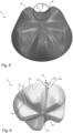
- FIG. 6 - 9 show various representations of a bottom area 2 of a plastic container 1 according to an embodiment of the present invention.
- Figures 6, 7 and 9 each show a representation of the bottom area 2 of the (plastic) container in different perspective views
- Fig. 8 shows the floor area in a sectional drawing.
- the floor area 2 shown here also has five feet 22 with each of these assigned standing areas 24.
- the feet here are preferably designed in the same way as those from the prior art, for example in the Figures 2 - 5 is illustrated.
- the base area 2 shown here also provides a groove base 33 that acts as a tension band.
- a groove base 33 is (precisely) arranged between two standing areas 24. Both the different stand areas and the groove bases 33 are designed (essentially) the same.
- the reference number 34 denotes the geometric center of a (respective) groove base 30 and the two reference numbers 32 and 34 each indicate a lateral tension band region of the groove base 33, which preferably extend essentially over two angle segments that are preferably different from one another in relation to the circumferential angle (in relation to the central axis of Plastic container), preferably extend essentially over the entire extent of the bottom region 2 as seen in the longitudinal direction L.
- the two lateral tension band regions 32 and 34 of a groove base 33 are preferably arranged on an opposite side with respect to the geometric center 34 of the tension band or the groove base 33.
- the bottom area 2 has a central drawstring area 44, in which the surface is curved towards the inside of the bottle.
- the curvature towards the inside of the bottle means that the drawstring fits better into the (bottom) geometry, so that the material can advantageously be stretched more easily into the feet.
- Illustrated bottom area 2 of a container according to the present invention is constructed in accordance with a preferred embodiment in such a way that the originally rotated surface between the (supporting) feet, which in particular forms the drawstring, is replaced by a free-form surface.
- the free-form cut makes it possible to distribute the material more precisely within the drawstring.
- Fig. 8 shows a representation of container 1 from the previous two Figures 6 and 7 , which is halved along a cutting plane which runs along the central axis M of the container or the longitudinal direction L and here along the geometric center 34 of a groove base 33, through the injection point 18 and a base 22.
- Fig. 8 illustrates that the surface of the groove base or the drawstring (not only curved towards the inside of the bottle, but also that the surface) can be changed in cross-section so that the material can be distributed and conditioned better and in a more targeted manner.
- the reference number 40 denotes a cross-sectional contour of a groove base or a tension band according to the prior art (represented for example by Fig. 2 - 5 , compare in particular Fig. 4 ), while reference number 42 represents an embodiment of a cross-sectional contour of the groove base 33 or the tension band according to an embodiment of the present invention.
- the cross-sectional contour 42 according to an embodiment of the present invention, here in particular in a middle height range of the container base 2 with respect to the longitudinal direction L, is arranged closer to the central axis M.
- the ones in the Fig. 6 - 9 offers the advantage that the formation of warps is avoided. Furthermore, the stability is increased. In addition, the blowability/formability is advantageously improved.
- Fig. 10 shows a schematic representation of an enlarged circular section K of the in Fig. 9 shown floor area 2, in which two adjacent feet 22 can be seen as well as a groove base lying between them, which here has the two side tension band areas 32 and 34 as well as a central tension band area, to which the arrow 35 marked by the reference number points.
- the upper edge area shows that the middle drawstring area is curved inwards (towards the inside of the container).
- This central tension band area extends along the geometric center 34 of the groove base 33 (essentially along the entire length of the bottom wall area formed by the geometric center 34 of the groove base).
- the two lateral tension band areas 32 and 34 are either curved inwards or curved outwards (as in Fig. 9 ), each preferably similar to a spherical segment, or straight.
- Fig. 11 shows a longitudinal section of the drawstring, ie a cross section through the container or the container base 2 through the drawstring or the groove bottom (here in a central drawstring area), the cross section extending along the longitudinal direction L and in particular along the central axis M of the container.
- the reference number 3 indicates the floor interior. Above (in the figure plane) the in the Fig. 11 The bottom area shown is followed by the bottle (base) body 50 (not shown here but the position of the area of the bottle body indicated by reference number 50).
- the longitudinal course of the drawstring can preferably be divided (particularly in the middle drawstring area) into different sections (seen in the longitudinal direction).
- the (longitudinal) section between S1 and S2 there is a so-called “upper tension band area” 49, which is preferably curved outwards.
- This is preferably followed by an upper transition section 48 in the (longitudinal) section between S2 and S3.
- This is adjoined in particular (in the figure in the (longitudinal) section between S3 and S4) by a main tension band region 45 (central in relation to the longitudinal direction).
- a lower transition region 47 in the (longitudinal) section between S4 and S5 and preferably followed by a lower tension band region 46, which is preferably designed as an inlet to the base center or to the injection point 18.
- the main drawstring area 45 or the central drawstring area relative to the longitudinal direction L preferably extends over at least 30%, preferably over at least 40%, preferably over at least 50% and particularly preferably over at least 70% of the longitudinal course of the drawstring (in particular the arc length of the drawstring within the longitudinal cross section through the tension band, preferably through the geometric center of the middle tension band area).
- the main drawstring area 45 or the middle drawstring area relative to the longitudinal direction L preferably extends over a maximum of 95%, preferably a maximum of 70% of the longitudinal course of the drawstring (in particular the arc length of the drawstring within the longitudinal cross section through the drawstring, preferably through the geometric center of the middle one drawstring area).
- the main drawstring area or the middle drawstring area relative to the longitudinal direction L extends over between 50% and 70% of the longitudinal course of the drawstring.
- the drawstring is curved inwards within the main drawstring area 45 in the middle drawstring area (relative to the circumferential direction).
- the reference numeral 40 indicates a longitudinal section of the drawstring according to a container base in an embodiment according to the prior art.
- the reference number 42 indicates the longitudinal section of the tension band according to a preferred embodiment of the present invention.
- Fig. 12a shows an exemplary representation of the container base to describe the drawstring cross section, in particular in addition to the various ones in Fig. 11 shown drawstring areas.
- reference number 22 denotes a base and the reference number 21 a foot flank surface, which is preferably designed as a free-form transition.
- reference number 33 denotes the bottom of the groove (colored in a darker gray), which forms the drawstring here.
- the upper drawstring area 49 in particular directly adjoins the container base body 50.
- the upper tension band region 49 in particular in the entire region, in particular in a cross section perpendicular to the longitudinal axis and/or central axis (i.e. in particular within a cross-sectional plane extending perpendicular to the longitudinal direction), is curved outwards.
- the upper drawstring area 49 preferably forms the connection to the bottle body.
- Fig. 12b illustrates the outward curvature of the upper tension band area 49 in a cross section perpendicular to the longitudinal axis L.
- the area (in the plane of the figure is the Fig. 12b ) above the upper drawstring area 49 shown in cross-sectional view (cross-section perpendicular to the longitudinal axis) is the floor interior marked with reference number 3, while the area below the upper drawstring area 49 shown in cross-sectional view is the container exterior.
- the reference number 5 indicates the outside space.
- the reference numeral 48 indicates, as in Fig. 11 , the upper transition area of the tension band or the groove base 33.
- the upper transition area 48 of the tension band or the groove base 33 is preferred as a compensating surface between the areas (here between the upper tension band area 49 and the central tension band area 45 or main tension band area, viewed in the longitudinal direction 45) designed in particular as a free-form surface.
- the reference numerals 44 and 45 indicate a central or main tension band region, viewed in the longitudinal direction L of the tension band, which is preferably arranged between the upper transition region 48 and a lower transition region 47.
- the lower transition region 47 is preferably provided as a transition between the (adjacent) regions, here in particular between the main tension band region 44, 45 and a lower tension band region 46.
- the lower tension band region 46 preferably represents an inlet to the floor center and/or injection point 18.
- the lower tension band region 46 preferably has no curvature in a (preferably any) cross section (in particular perpendicular to the longitudinal direction L).
- the lower tension band region 46 is preferably designed to be essentially planar or even.
- the lower transition region 47 is preferably designed as a free-form transition.
- the reference numeral 44 denotes a central tension band region (seen in the circumferential direction U) (here the main tension band region or the middle tension band region seen in the longitudinal direction).
- This middle tension band region 44 (seen in the circumferential direction U) is seen in the circumferential direction U between two lateral tension band regions, which also referred to as the “flanks” of the tension band and are marked with the reference numbers 32 and 36.
- Fig. 12c illustrates that the middle tension band region 44 (seen in the circumferential direction U) ("middle tension band region - "middle"), particularly in the middle tension band region seen in the longitudinal direction L or in the main tension band region 45, is always curved inwards in cross section (perpendicular to the longitudinal axis).
- the area (in the figure plane of the Fig. 12c ) above the upper drawstring area 44 shown in cross-section (cross-section perpendicular to the longitudinal axis) is the floor interior (marked with reference number 3), while the area below the upper drawstring area 49 shown in cross-section is the container exterior.
- the reference number 5 indicates the outside space.
- the two reference numbers 45 indicate in Fig. 12 a in the central tension band area (seen in the longitudinal direction) there is a so-called "flank" of the tension band or the groove base 33.
- the two reference numbers 45 identify in particular the two side ones Drawstring areas 32 and 36 of the main drawstring area 45 or the middle drawstring area seen in the longitudinal direction L.
- Each of these "flanks" 45 of the central tension band region (seen in the longitudinal direction) or of the main tension band region 45 is preferably curved inwards, but can also be curved outwards or be linear.
- the Figure 12d illustrates this by showing three different tension band cross sections (where the cross-sectional plane runs perpendicular to the longitudinal direction L) through the middle tension band area seen in the longitudinal direction L or through the main tension band area 45.
- the middle section of the three tension band cross sections shown each shows the (in the circumferential direction U seen) middle drawstring area 44 and the two outer sections each show a "flank" 45 or the side drawstring areas 32, 36 of the main drawstring area 45.
- the top representation of the Fig. 12d shows a preferred embodiment in which the lateral tension band regions 32, 36 of the main tension band region 45 are curved inwards in cross section (i.e. here within a cross-sectional plane perpendicular to the longitudinal axis L).
- both the central tension band section 44 (seen in the circumferential direction U) and the two side “flank" tension band regions 45 are curved inwards.
- Fig. 12 b,c is also in Fig. 12d the area (in the figure plane of the Fig. 12d ) above the respective drawstring area 44, 45 shown in a cross-sectional view (cross-section perpendicular to the longitudinal axis) is the floor interior, while the area below the drawstring area 44, 45 shown in a cross-sectional view is the outer space of the container.
- the middle representation of the Fig. 12d shows an alternative preferred embodiment in which the lateral tension band regions 32, 36 of the main tension band region 45 are curved outwards in cross section (i.e. here within a cross-sectional plane perpendicular to the longitudinal axis L).
- the curvature of the container wall area of the middle drawstring section 44 (seen in the circumferential direction U) with the inward curvature is oriented in the opposite direction compared to the curvature of the two side "flank" drawstring areas 45 (both curved outwards).
- the lower representation of the Fig. 12d shows a further alternative preferred embodiment, in which the lateral tension band regions 32, 36 of the main tension band region 45 have no curvature in cross section (i.e. here within a cross-sectional plane perpendicular to the longitudinal axis L), but are designed linearly.
- the respective lateral "flank" drawstring area 45 is not curved (but runs linearly or in a straight line).
Landscapes
- Engineering & Computer Science (AREA)
- Ceramic Engineering (AREA)
- Mechanical Engineering (AREA)
- Containers Having Bodies Formed In One Piece (AREA)
Applications Claiming Priority (1)
| Application Number | Priority Date | Filing Date | Title |
|---|---|---|---|
| DE102022120143.0A DE102022120143A1 (de) | 2022-08-10 | 2022-08-10 | Kunststoffbehältnis mit Zugbandgeometrie am Bodenbereich |
Publications (1)
| Publication Number | Publication Date |
|---|---|
| EP4321447A1 true EP4321447A1 (fr) | 2024-02-14 |
Family
ID=87556404
Family Applications (1)
| Application Number | Title | Priority Date | Filing Date |
|---|---|---|---|
| EP23189463.5A Pending EP4321447A1 (fr) | 2022-08-10 | 2023-08-03 | Récipient en matière plastique avec géométrie de bande de traction au niveau du fond |
Country Status (4)
| Country | Link |
|---|---|
| US (1) | US20240051700A1 (fr) |
| EP (1) | EP4321447A1 (fr) |
| CN (1) | CN117585272B (fr) |
| DE (1) | DE102022120143A1 (fr) |
Citations (6)
| Publication number | Priority date | Publication date | Assignee | Title |
|---|---|---|---|---|
| EP2036820A2 (fr) | 2007-08-21 | 2009-03-18 | Krones AG | Bouteille en plastique |
| DE102013110139A1 (de) | 2013-09-13 | 2015-03-19 | Krones Ag | Kunststoffbehältnis mit wärmestabilem Boden |
| US9623999B2 (en) * | 2011-04-12 | 2017-04-18 | Sidel Participations | Double-valley petaloid container bottom |
| US20170121049A1 (en) * | 2014-06-13 | 2017-05-04 | Sidel Participations | Container provided with a base with bulging beams |
| EP3538444A1 (fr) * | 2016-11-14 | 2019-09-18 | Amcor Rigid Plastics USA, LLC | Base de contenant léger |
| DE102019119984A1 (de) | 2019-07-24 | 2021-01-28 | Krones Ag | Kunststoffbehältnis mit Zugbandgeometrie am Bodenbereich |
Family Cites Families (8)
| Publication number | Priority date | Publication date | Assignee | Title |
|---|---|---|---|---|
| MXPA05002660A (es) * | 2005-03-09 | 2006-09-08 | Pepsico Inc | Botella de bebidas con compartimiento inferior desmontable y metodos para usar la misma. |
| FR2894509B1 (fr) * | 2005-12-08 | 2008-02-15 | Sidel Sas | Procede et dispositif de moulage par etirage-soufflage de recipients, notamment de bouteilles, en matiere thermoplastique a fond petaloide. |
| FR2959214B1 (fr) * | 2010-04-21 | 2012-06-29 | Sidel Participations | Fond de recipient petaloide renforce |
| FR2967975B1 (fr) * | 2010-11-25 | 2012-12-28 | Sidel Participations | Fond de recipient petaloide combine |
| FR3045571B1 (fr) * | 2015-12-16 | 2018-01-26 | Sidel Participations | Recipient a fond petaloide a pieds nervures |
| JP7748176B2 (ja) * | 2017-06-12 | 2025-10-02 | ソシエテ・デ・プロデュイ・ネスレ・エス・アー | 二重凹状アーチが設けられている容器底部ベース |
| JP7454914B2 (ja) * | 2019-03-29 | 2024-03-25 | サントリーホールディングス株式会社 | プラスチックボトル |
| GB2636920B (en) * | 2020-11-11 | 2025-10-22 | Niagara Bottling Llc | Swirl bell bottle with wavy ribs |
-
2022
- 2022-08-10 DE DE102022120143.0A patent/DE102022120143A1/de active Pending
-
2023
- 2023-08-03 EP EP23189463.5A patent/EP4321447A1/fr active Pending
- 2023-08-08 CN CN202310990776.1A patent/CN117585272B/zh active Active
- 2023-08-10 US US18/232,735 patent/US20240051700A1/en active Pending
Patent Citations (6)
| Publication number | Priority date | Publication date | Assignee | Title |
|---|---|---|---|---|
| EP2036820A2 (fr) | 2007-08-21 | 2009-03-18 | Krones AG | Bouteille en plastique |
| US9623999B2 (en) * | 2011-04-12 | 2017-04-18 | Sidel Participations | Double-valley petaloid container bottom |
| DE102013110139A1 (de) | 2013-09-13 | 2015-03-19 | Krones Ag | Kunststoffbehältnis mit wärmestabilem Boden |
| US20170121049A1 (en) * | 2014-06-13 | 2017-05-04 | Sidel Participations | Container provided with a base with bulging beams |
| EP3538444A1 (fr) * | 2016-11-14 | 2019-09-18 | Amcor Rigid Plastics USA, LLC | Base de contenant léger |
| DE102019119984A1 (de) | 2019-07-24 | 2021-01-28 | Krones Ag | Kunststoffbehältnis mit Zugbandgeometrie am Bodenbereich |
Also Published As
| Publication number | Publication date |
|---|---|
| DE102022120143A1 (de) | 2024-02-15 |
| US20240051700A1 (en) | 2024-02-15 |
| CN117585272A (zh) | 2024-02-23 |
| CN117585272B (zh) | 2026-04-17 |
Similar Documents
| Publication | Publication Date | Title |
|---|---|---|
| EP2986517B1 (fr) | Récipient de boisson en matière synthétique et moule de soufflage pour sa fabrication | |
| AT395573B (de) | Behaelter aus kunststoff mit kreisfoermigem querschnitt | |
| DE102012003219B4 (de) | Kunststoffbehältnis | |
| EP3770073A1 (fr) | Récipient en matière plastique à géométrie à bande de traction dans la zone de fond | |
| DE69706429T2 (de) | Verbesserte metalbehalter und verfahren zur herstellung | |
| DE3855880T2 (de) | Einteiliger, selbststehender, blasgeformter Kunststoffbehälter | |
| EP2735517B1 (fr) | Récipient en plastique avec un fond base renforcé | |
| DE3874558T2 (de) | Blasgeformter kunststoffbehaelter. | |
| EP2764979B1 (fr) | Récipient en matière plastique | |
| EP2925615B1 (fr) | Récipient en matière plastique | |
| EP2679507B1 (fr) | Récipient en matière plastique muni de portions de col rectilignes | |
| EP3458370A1 (fr) | Bouteille en matière plastique munie de bandes de tension en intersection | |
| DE68913263T2 (de) | Behälter. | |
| DE69004033T2 (de) | Eigenstabiler Boden für Druckflaschen. | |
| DE602006000329T2 (de) | Kunststoffflasche mit verstärktem Boden | |
| DE69817023T2 (de) | Behälter aus thermoplastischem kunststoff mit blütenförmigem boden | |
| EP4321447A1 (fr) | Récipient en matière plastique avec géométrie de bande de traction au niveau du fond | |
| EP2468645B1 (fr) | Récipient en matériau thermoplastique | |
| DE102013110139A1 (de) | Kunststoffbehältnis mit wärmestabilem Boden | |
| EP4450410A1 (fr) | Récipient en matière plastique avec pieds aplatis et dispositif de moulage par soufflage | |
| DD300086A5 (de) | Vorrichtung und Verfahren in Verbindung mit einem Vorformling mit geodätischen Verstärkungsring | |
| EP4169840A1 (fr) | Récipient en matière plastique pour boissons à stabilité améliorée | |
| WO2017060293A1 (fr) | Préforme pour la fabrication d'un récipient en matériau synthétique dans un procédé d'étirage-soufflage | |
| DE102019105005A1 (de) | Kunststoffbehältnis mit Rillengeometrie | |
| EP3601072B1 (fr) | Contenant en matière plastique à partie fond pivotante |
Legal Events
| Date | Code | Title | Description |
|---|---|---|---|
| PUAI | Public reference made under article 153(3) epc to a published international application that has entered the european phase |
Free format text: ORIGINAL CODE: 0009012 |
|
| STAA | Information on the status of an ep patent application or granted ep patent |
Free format text: STATUS: THE APPLICATION HAS BEEN PUBLISHED |
|
| AK | Designated contracting states |
Kind code of ref document: A1 Designated state(s): AL AT BE BG CH CY CZ DE DK EE ES FI FR GB GR HR HU IE IS IT LI LT LU LV MC ME MK MT NL NO PL PT RO RS SE SI SK SM TR |
|
| STAA | Information on the status of an ep patent application or granted ep patent |
Free format text: STATUS: REQUEST FOR EXAMINATION WAS MADE |
|
| 17P | Request for examination filed |
Effective date: 20240812 |
|
| RBV | Designated contracting states (corrected) |
Designated state(s): AL AT BE BG CH CY CZ DE DK EE ES FI FR GB GR HR HU IE IS IT LI LT LU LV MC ME MK MT NL NO PL PT RO RS SE SI SK SM TR |