EP4450410A1 - Récipient en matière plastique avec pieds aplatis et dispositif de moulage par soufflage - Google Patents
Récipient en matière plastique avec pieds aplatis et dispositif de moulage par soufflage Download PDFInfo
- Publication number
- EP4450410A1 EP4450410A1 EP24166799.7A EP24166799A EP4450410A1 EP 4450410 A1 EP4450410 A1 EP 4450410A1 EP 24166799 A EP24166799 A EP 24166799A EP 4450410 A1 EP4450410 A1 EP 4450410A1
- Authority
- EP
- European Patent Office
- Prior art keywords
- base
- region
- area
- curvature
- groove
- Prior art date
- Legal status (The legal status is an assumption and is not a legal conclusion. Google has not performed a legal analysis and makes no representation as to the accuracy of the status listed.)
- Pending
Links
- 238000000071 blow moulding Methods 0.000 title claims description 68
- 230000015572 biosynthetic process Effects 0.000 claims description 19
- 238000013022 venting Methods 0.000 claims description 16
- 230000002829 reductive effect Effects 0.000 claims description 5
- 238000002347 injection Methods 0.000 description 26
- 239000007924 injection Substances 0.000 description 26
- 230000007704 transition Effects 0.000 description 21
- 230000008901 benefit Effects 0.000 description 16
- 238000010276 construction Methods 0.000 description 16
- 238000007664 blowing Methods 0.000 description 13
- 238000005520 cutting process Methods 0.000 description 12
- 239000000463 material Substances 0.000 description 10
- 238000004519 manufacturing process Methods 0.000 description 8
- 238000013461 design Methods 0.000 description 7
- 230000009467 reduction Effects 0.000 description 6
- 230000007423 decrease Effects 0.000 description 5
- 239000002689 soil Substances 0.000 description 5
- 238000009423 ventilation Methods 0.000 description 5
- 238000012360 testing method Methods 0.000 description 4
- 238000012546 transfer Methods 0.000 description 4
- 238000005553 drilling Methods 0.000 description 3
- 230000009969 flowable effect Effects 0.000 description 3
- 239000012530 fluid Substances 0.000 description 3
- 238000000034 method Methods 0.000 description 3
- 230000008569 process Effects 0.000 description 3
- 239000008186 active pharmaceutical agent Substances 0.000 description 2
- 235000013361 beverage Nutrition 0.000 description 2
- 235000014171 carbonated beverage Nutrition 0.000 description 2
- 230000001419 dependent effect Effects 0.000 description 2
- 238000011161 development Methods 0.000 description 2
- 230000018109 developmental process Effects 0.000 description 2
- 230000003628 erosive effect Effects 0.000 description 2
- 238000002474 experimental method Methods 0.000 description 2
- 238000011838 internal investigation Methods 0.000 description 2
- 230000006978 adaptation Effects 0.000 description 1
- 238000009411 base construction Methods 0.000 description 1
- 230000005540 biological transmission Effects 0.000 description 1
- 230000008859 change Effects 0.000 description 1
- 230000004069 differentiation Effects 0.000 description 1
- 238000006073 displacement reaction Methods 0.000 description 1
- 238000009826 distribution Methods 0.000 description 1
- 230000006872 improvement Effects 0.000 description 1
- 238000003698 laser cutting Methods 0.000 description 1
- 238000003801 milling Methods 0.000 description 1
- 230000036961 partial effect Effects 0.000 description 1
- 230000002093 peripheral effect Effects 0.000 description 1
- 238000012887 quadratic function Methods 0.000 description 1
- 230000000717 retained effect Effects 0.000 description 1
- 238000007493 shaping process Methods 0.000 description 1
- 239000000243 solution Substances 0.000 description 1
- 238000012549 training Methods 0.000 description 1
- 230000003313 weakening effect Effects 0.000 description 1
Images








Classifications
-
- B—PERFORMING OPERATIONS; TRANSPORTING
- B65—CONVEYING; PACKING; STORING; HANDLING THIN OR FILAMENTARY MATERIAL
- B65D—CONTAINERS FOR STORAGE OR TRANSPORT OF ARTICLES OR MATERIALS, e.g. BAGS, BARRELS, BOTTLES, BOXES, CANS, CARTONS, CRATES, DRUMS, JARS, TANKS, HOPPERS, FORWARDING CONTAINERS; ACCESSORIES, CLOSURES, OR FITTINGS THEREFOR; PACKAGING ELEMENTS; PACKAGES
- B65D1/00—Rigid or semi-rigid containers having bodies formed in one piece, e.g. by casting metallic material, by moulding plastics, by blowing vitreous material, by throwing ceramic material, by moulding pulped fibrous material or by deep-drawing operations performed on sheet material
- B65D1/02—Bottles or similar containers with necks or like restricted apertures, designed for pouring contents
- B65D1/0223—Bottles or similar containers with necks or like restricted apertures, designed for pouring contents characterised by shape
- B65D1/0261—Bottom construction
- B65D1/0284—Bottom construction having a discontinuous contact surface, e.g. discrete feet
-
- B—PERFORMING OPERATIONS; TRANSPORTING
- B29—WORKING OF PLASTICS; WORKING OF SUBSTANCES IN A PLASTIC STATE IN GENERAL
- B29C—SHAPING OR JOINING OF PLASTICS; SHAPING OF MATERIAL IN A PLASTIC STATE, NOT OTHERWISE PROVIDED FOR; AFTER-TREATMENT OF THE SHAPED PRODUCTS, e.g. REPAIRING
- B29C49/00—Blow-moulding, i.e. blowing a preform or parison to a desired shape within a mould; Apparatus therefor
- B29C49/28—Blow-moulding apparatus
-
- B—PERFORMING OPERATIONS; TRANSPORTING
- B29—WORKING OF PLASTICS; WORKING OF SUBSTANCES IN A PLASTIC STATE IN GENERAL
- B29C—SHAPING OR JOINING OF PLASTICS; SHAPING OF MATERIAL IN A PLASTIC STATE, NOT OTHERWISE PROVIDED FOR; AFTER-TREATMENT OF THE SHAPED PRODUCTS, e.g. REPAIRING
- B29C49/00—Blow-moulding, i.e. blowing a preform or parison to a desired shape within a mould; Apparatus therefor
- B29C49/42—Component parts, details or accessories; Auxiliary operations
- B29C49/48—Moulds
-
- B—PERFORMING OPERATIONS; TRANSPORTING
- B29—WORKING OF PLASTICS; WORKING OF SUBSTANCES IN A PLASTIC STATE IN GENERAL
- B29C—SHAPING OR JOINING OF PLASTICS; SHAPING OF MATERIAL IN A PLASTIC STATE, NOT OTHERWISE PROVIDED FOR; AFTER-TREATMENT OF THE SHAPED PRODUCTS, e.g. REPAIRING
- B29C49/00—Blow-moulding, i.e. blowing a preform or parison to a desired shape within a mould; Apparatus therefor
- B29C49/42—Component parts, details or accessories; Auxiliary operations
- B29C49/62—Venting means
-
- B—PERFORMING OPERATIONS; TRANSPORTING
- B65—CONVEYING; PACKING; STORING; HANDLING THIN OR FILAMENTARY MATERIAL
- B65D—CONTAINERS FOR STORAGE OR TRANSPORT OF ARTICLES OR MATERIALS, e.g. BAGS, BARRELS, BOTTLES, BOXES, CANS, CARTONS, CRATES, DRUMS, JARS, TANKS, HOPPERS, FORWARDING CONTAINERS; ACCESSORIES, CLOSURES, OR FITTINGS THEREFOR; PACKAGING ELEMENTS; PACKAGES
- B65D1/00—Rigid or semi-rigid containers having bodies formed in one piece, e.g. by casting metallic material, by moulding plastics, by blowing vitreous material, by throwing ceramic material, by moulding pulped fibrous material or by deep-drawing operations performed on sheet material
- B65D1/02—Bottles or similar containers with necks or like restricted apertures, designed for pouring contents
- B65D1/0223—Bottles or similar containers with necks or like restricted apertures, designed for pouring contents characterised by shape
- B65D1/0261—Bottom construction
-
- B—PERFORMING OPERATIONS; TRANSPORTING
- B65—CONVEYING; PACKING; STORING; HANDLING THIN OR FILAMENTARY MATERIAL
- B65D—CONTAINERS FOR STORAGE OR TRANSPORT OF ARTICLES OR MATERIALS, e.g. BAGS, BARRELS, BOTTLES, BOXES, CANS, CARTONS, CRATES, DRUMS, JARS, TANKS, HOPPERS, FORWARDING CONTAINERS; ACCESSORIES, CLOSURES, OR FITTINGS THEREFOR; PACKAGING ELEMENTS; PACKAGES
- B65D1/00—Rigid or semi-rigid containers having bodies formed in one piece, e.g. by casting metallic material, by moulding plastics, by blowing vitreous material, by throwing ceramic material, by moulding pulped fibrous material or by deep-drawing operations performed on sheet material
- B65D1/40—Details of walls
-
- B—PERFORMING OPERATIONS; TRANSPORTING
- B65—CONVEYING; PACKING; STORING; HANDLING THIN OR FILAMENTARY MATERIAL
- B65D—CONTAINERS FOR STORAGE OR TRANSPORT OF ARTICLES OR MATERIALS, e.g. BAGS, BARRELS, BOTTLES, BOXES, CANS, CARTONS, CRATES, DRUMS, JARS, TANKS, HOPPERS, FORWARDING CONTAINERS; ACCESSORIES, CLOSURES, OR FITTINGS THEREFOR; PACKAGING ELEMENTS; PACKAGES
- B65D11/00—Containers having bodies formed by interconnecting or uniting two or more rigid, or substantially rigid, components made wholly or mainly of plastics material
- B65D11/02—Containers having bodies formed by interconnecting or uniting two or more rigid, or substantially rigid, components made wholly or mainly of plastics material of curved cross-section
-
- B—PERFORMING OPERATIONS; TRANSPORTING
- B65—CONVEYING; PACKING; STORING; HANDLING THIN OR FILAMENTARY MATERIAL
- B65D—CONTAINERS FOR STORAGE OR TRANSPORT OF ARTICLES OR MATERIALS, e.g. BAGS, BARRELS, BOTTLES, BOXES, CANS, CARTONS, CRATES, DRUMS, JARS, TANKS, HOPPERS, FORWARDING CONTAINERS; ACCESSORIES, CLOSURES, OR FITTINGS THEREFOR; PACKAGING ELEMENTS; PACKAGES
- B65D11/00—Containers having bodies formed by interconnecting or uniting two or more rigid, or substantially rigid, components made wholly or mainly of plastics material
- B65D11/20—Details of walls made of plastics material
-
- B—PERFORMING OPERATIONS; TRANSPORTING
- B65—CONVEYING; PACKING; STORING; HANDLING THIN OR FILAMENTARY MATERIAL
- B65D—CONTAINERS FOR STORAGE OR TRANSPORT OF ARTICLES OR MATERIALS, e.g. BAGS, BARRELS, BOTTLES, BOXES, CANS, CARTONS, CRATES, DRUMS, JARS, TANKS, HOPPERS, FORWARDING CONTAINERS; ACCESSORIES, CLOSURES, OR FITTINGS THEREFOR; PACKAGING ELEMENTS; PACKAGES
- B65D23/00—Details of bottles or jars not otherwise provided for
-
- B—PERFORMING OPERATIONS; TRANSPORTING
- B29—WORKING OF PLASTICS; WORKING OF SUBSTANCES IN A PLASTIC STATE IN GENERAL
- B29C—SHAPING OR JOINING OF PLASTICS; SHAPING OF MATERIAL IN A PLASTIC STATE, NOT OTHERWISE PROVIDED FOR; AFTER-TREATMENT OF THE SHAPED PRODUCTS, e.g. REPAIRING
- B29C49/00—Blow-moulding, i.e. blowing a preform or parison to a desired shape within a mould; Apparatus therefor
- B29C49/42—Component parts, details or accessories; Auxiliary operations
- B29C49/48—Moulds
- B29C2049/4879—Moulds characterised by mould configurations
- B29C2049/4882—Mould cavity geometry
-
- B—PERFORMING OPERATIONS; TRANSPORTING
- B29—WORKING OF PLASTICS; WORKING OF SUBSTANCES IN A PLASTIC STATE IN GENERAL
- B29C—SHAPING OR JOINING OF PLASTICS; SHAPING OF MATERIAL IN A PLASTIC STATE, NOT OTHERWISE PROVIDED FOR; AFTER-TREATMENT OF THE SHAPED PRODUCTS, e.g. REPAIRING
- B29C49/00—Blow-moulding, i.e. blowing a preform or parison to a desired shape within a mould; Apparatus therefor
- B29C49/42—Component parts, details or accessories; Auxiliary operations
- B29C49/62—Venting means
- B29C2049/622—Venting means for venting air between preform and cavity, e.g. using venting holes, gaps or patterned moulds
-
- B—PERFORMING OPERATIONS; TRANSPORTING
- B29—WORKING OF PLASTICS; WORKING OF SUBSTANCES IN A PLASTIC STATE IN GENERAL
- B29L—INDEXING SCHEME ASSOCIATED WITH SUBCLASS B29C, RELATING TO PARTICULAR ARTICLES
- B29L2031/00—Other particular articles
- B29L2031/712—Containers; Packaging elements or accessories, Packages
- B29L2031/7158—Bottles
Definitions
- the present invention relates to a plastic container, preferably a PET plastic container and/or a plastic bottle.
- the present invention relates to a plastic container for drinks.
- the invention is also directed to a base structure for such a plastic container.
- plastic containers are usually produced by blow molding processes and in particular stretch blow molding processes. For this purpose, heated plastic preforms are expanded in particular within blow molds to form plastic containers or plastic bottles.
- So-called petaloid bottle bottoms are known from the state of the art.
- Containers with a petaloid bottle bottom have a large number of feet, often five feet.
- the container bottoms bear the weight of the filled bottles and are therefore exposed to relatively high loads. It is known from the state of the art that grooves run between these feet.
- a so-called tension band is used in the state of the art, for which the use of a rotated surface as a tension band between the (standing) feet is known from the state of the art, which collects more material in order to hold the bottom center in position, similar to a "seat belt", even under internal pressure and temperature influences.
- a plastic container with a petaloid base in which a tension band is formed as a groove base between two adjacent feet, which is curved outwards and has a constant curvature in the circumferential direction.
- the base wall of the container is thus curved outwards, particularly in the area of a groove base and particularly in the area of a geometric nut of the groove base, comparable to an area of a spherical surface. It is also described that the tension band surface is created by rotation around a rotation axis.
- the plastic preforms are subjected to blowing air (and/or fluid blowing medium) at a (finished) blowing pressure of over 20 bar.
- blowing air and/or fluid blowing medium
- the disadvantage is that a comparatively high pressure of the blowing air is required to form the container, which is reflected in the production costs.
- the final blow molding pressure i.e. the pressure with which the plastic preform is completely formed, represents a significant proportion of the energy requirement of the blow molding process, so this should be as low as possible.
- the level of the final blow molding pressure is particularly determined by the shape of the last corners of the container, especially in the corner areas of the feet of a petaloid base, for example.
- the present invention is based on the object of overcoming the disadvantages known from the prior art and of providing a plastic container and a blow molding device for producing these plastic containers, which allow energy-efficient production so that the production costs of the container and thus also the energy costs can be reduced.
- the object is to achieve a high level of base stability for the container and to provide the best possible distribution of the plastic material during the production of the plastic container (for example in a stretch blow molding process in which a plastic preform is pressed against a blow mold having a base shape by means of exposure to a fluid medium).
- a plastic container according to the invention in particular for drinks, has a base region, a base body adjoining this base region in the longitudinal direction of the plastic container and a mouth region with a container mouth adjoining this base body at least indirectly in the longitudinal direction.
- the base area has at least three feet, preferably at least five and particularly preferably exactly five feet.
- the base area is preferably designed as a petaloid base.
- the longitudinal direction is in particular a direction along a central axis of the plastic container.
- the central axis of the plastic container extends in particular (centrally) through the (opening of the) container mouth (and also in particular centrally through a base region of the container and/or through a base center of the base region, in particular through an injection point).
- the central axis In the (upright) standing position of the container, the central axis extends in particular parallel to a vertical direction.
- the longitudinal direction preferably runs from a base region (along the central axis) in the direction of the mouth region of the plastic container.
- a circumferential direction is preferably understood to mean a direction of rotation about the central axis (or longitudinal direction) of the container (selected as the axis of rotation).
- a radial direction (relative to the longitudinal direction and/or the central axis) is understood below to mean a direction relative to the longitudinal direction (or the central axis of the container) which is perpendicular to the longitudinal direction (or the central axis) and which in particular moves away from this (in particular from the central axis) (in a straight line and in particular in a direction perpendicular to the central axis).
- Each of these (at least three) feet has at least one standing area extending in the circumferential direction with respect to the longitudinal direction over a standing area circumferential angle (as well as in the radial direction with respect to the longitudinal direction) with at least one, in particular substantially flat, standing surface for the plastic container to stand upright.
- the standing surface of a foot forms on a standing plane (upright or on its base area or on its at least three Stand feet) standing state the contact area of the stand between the stand foot and the standing surface.
- the standing area circumferential angle is selected from an angle range between 5° and 15°, preferably between 7° and 12° and particularly preferably between 8° and 10° and particularly preferably substantially at 9°.
- the base area preferably extends over the entire base area circumferential angle.
- the base area preferably extends from the bottom center (in particular the injection point) to the base body.
- the base area preferably extends essentially along its complete radial extension over the essentially complete base area circumferential angle. In other words, the base area extends at every distance from the central axis over almost the same angle, the base area circumferential angle.
- the base area is preferably constructed or designed essentially the same in the circumferential direction (at least one main extension area of the base area).
- each base has exactly one standing surface.
- the standing surface in each case is formed in the shape of a circular ring segment.
- the circumferential angle is preferably understood to mean an angle in the circumferential direction around the central axis after a projection into a plane perpendicular to the central axis.
- the standing area circumference over which the standing area extends is measured (as an angle in the circumferential direction around the central axis) on the projection of the standing area into a plane perpendicular to the longitudinal axis.
- At least one groove with a groove base - preferably acting as a tension band (in particular between a base center, such as an injection point, of the base area and the base body) - is arranged.
- the groove base preferably widens outwards in the radial direction of the plastic container.
- the widening preferably continuous and particularly preferably linear
- Widening takes place with increasing distance from the central axis and/or the base center. Widening is understood in particular to mean that a width of the groove base (where width is understood to mean an extension in the circumferential direction) is increased outwards in a radial direction of the container.
- the groove base in particular from a predetermined distance from the central axis, in particular essentially
- has the same width i.e. in particular (where width is understood to mean an extension in the circumferential direction).
- width is understood to mean an extension in the circumferential direction.
- the width of the groove base or the extension of the groove base in the circumferential direction could remain (essentially) constant, in particular over the entire remaining region of the groove base and/or over the entire remaining region of the groove base excluding an end section.
- the predetermined distance from the central axis is (essentially) the same for at least two, preferably for at least three, for at least four and particularly preferably for all groove bases.
- the groove base preferably extends in the circumferential direction over a (predetermined) groove base circumferential angle.
- the groove base acts as a tension band.
- the groove base preferably forms the tension band (essentially completely and preferably completely).
- the groove base is designed over the (predetermined) circumferential angle in such a way (in particular through its shape) that it acts as a tension band or is suitable for acting as a tension band.
- the groove base preferably essentially follows a hemispherical and/or ellipsoidal course.
- the bottom center (in particular the injection point, which preferably forms the bottom center) does not contact the base level when the plastic container is standing upright on a base level, but is spaced from the flat base level by the so-called ground clearance.
- the bottom center does not contact the base level when the plastic container is standing upright on a base level, but is spaced from the flat base level by the so-called ground clearance.
- only the (base areas of the base areas of the) base feet touch the base level.
- the container is preferably designed in one piece.
- the groove base circumferential angle over which the groove base extends is measured (as an angle in the circumferential direction around the central axis) at the projection of the groove base into a plane perpendicular to the longitudinal axis.
- the at least three feet are (each) delimited in the circumferential direction (and counter to the circumferential direction) by at least one foot side region and in a radial outward direction by a foot outer region.
- the main extension direction of a normal vector is directed in the radial direction (but not in or against the circumferential direction and/or in or against the longitudinal direction).
- the main extension direction of the normal vector is understood to mean in particular the direction selected from the directions (in or against) the circumferential direction, (in or against) the radial direction and (in or against) the longitudinal direction in which the component of the normal vector is greatest.
- the main extension direction of a normal vector is directed in (or against) the circumferential direction (but not in or against the radial direction and/or in or against the longitudinal direction).
- the main extension direction of a normal vector is directed in or against the longitudinal direction (but not in or against the radial direction and/or in or against the circumferential direction).
- the outer foot area borders on the standing area and/or preferably overlaps with the standing area in some areas, namely in the area in which the Main extension direction of the normal vector of the standing area points in the radial direction.
- the standing area also has areas in which the normal vector of each point of the standing area has a main extension direction in the radial direction.
- the outer base region (at least in sections) is designed in the manner and/or similar to a region of a lateral surface of a cylinder.
- the base side region extends only within a very narrow angular segment and extends almost over the complete (maximum) radial extent of the plastic container and/or extends (essentially or almost) from the base center to (almost) a maximum radial extent of the base region at the same height in relation to the longitudinal direction.
- the main extension directions of the foot side area are the radial direction and the longitudinal direction.
- the main extension directions of the foot outer area are the circumferential direction and the longitudinal direction.
- the main extension directions of the standing surface are preferably in the circumferential direction and in the radial direction.
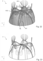
- the at least three feet preferably the at least five feet, have (each) at least one flattening region in a corner region of the feet, in which the standing region, the foot side region and the foot outer region meet, which causes a flattening of the respective foot in the corner region.
- the corner region is arranged between the standing region (and/or the standing surface), the foot side region and the foot outer region.
- the invention is described below (mostly) in relation to a base and (at least) one adjacent and/or neighboring groove (and its groove base).
- all other bases of the at least three and/or at least five bases and preferably all other bases of the base area are designed in the same way.
- all bases and/or each groove and/or each groove base are designed identically.
- a flattening is preferably understood to mean that this area has a less pronounced curvature or curvature than an adjacent area.
- the corner region having the flattened region deviates from a spherical (segment) shape.
- the flattened region is arranged substantially centrally and/or centrally in the corner region.
- the flattened area preferably has a curved and/or arched outer surface.
- the (essentially) entire flattened area and/or corner area is arched outwards and/or convex.
- curved outwards means in particular that the wall of the container in the respective area is curved towards the outside of the container.
- curved outwards means in particular that the container wall, in particular the outer surface of the container, is convex in the respective area (whereby “convex” here means in particular that a straight line between any selectable points of this surface (this area) runs completely inside the container (in particular completely inside the base area) and/or not outside the container).
- the base side area of the base and/or the corner area and/or the flattened area are not curved inwards.
- the corner area and/or the flattened area are connected areas.
- curved inwards is to be understood in particular as meaning that the wall of the container in the respective area is curved towards the inside of the container (i.e. towards the inside of the bottle, for example).
- “Curved inwards” is to be understood in particular as meaning that the container wall, in particular the outer surface of the container, is concave in the respective area (where “concave” here means in particular that a straight line between any selectable points of this surface or area runs completely outside the container wall and/or completely outside the container and/or not inside the container).
- a region of the container base that is convexly curved in both main curvature directions is understood to mean in particular that the tangential plane in any Point of the area extends or is arranged at least in the tangential plane area surrounding the point outside the container and/or not inside the container.
- a region of the container base which is concavely curved in both main curvature directions is understood to mean in particular that the tangential plane in any point of the region does not run or is arranged inside the container and/or (completely) outside the container, at least in the tangential plane region surrounding the point.
- the corner area represents in particular a transition area between the standing area (and/or the standing surface), the foot side area and the foot outer area.
- the flattening in particular ensures that a transition between the standing area and the foot side area, between the standing area and the foot outer area and/or between the foot side area and the standing area (and/or the standing surface) does not meet at essentially one corner point.
- the container base in this area is positioned closer to the drawstring or groove base and/or is better reached by the latter during the blow molding process of the plastic preform.
- the flattened area offers the significant advantage that a significantly lower blowing pressure is required to form the corner area or the feet.
- the applicant has compared it with a base area of the design without a flattened area, for example the one in the patent application DE 10 2013 110 139 A1 described base area of the applicant, it was found that the flattening means that a significantly lower blowing pressure is required to produce a plastic container that is evenly shaped in all areas. In particular, even with a lower blowing pressure, the respective corner areas or the outer areas of the feet are well formed (thanks to the provision of the flattening area).
- an edge area between the bottom area of the foot and the outer area of the foot, an edge area between the outer area of the foot and the side area of the foot and an edge area between the side area of the foot and the bottom area of the foot can be defined.
- the components of the normal vector are the same size in two directions.
- the components of the normal vector are the same size in the radial direction and in the circumferential direction.
- the edge areas therefore preferably represent transition areas in which, for example, the outer area of the foot, which faces essentially (radially) outwards, transitions into the side area of the foot, which faces essentially in the circumferential direction.
- the edge region between the outer foot region and the foot side region preferably opens into the flattened region at a different opening region than the edge region between the outer foot region and the lower foot region and preferably at a different opening region into the flattened region than the edge region between the foot side region and the lower foot region.
- the edge region between the lower foot region and the foot side region opens into the flattened region at a different opening region than the edge region between the foot side region and the outer foot region.
- edge areas do not meet.
- two edge areas do not meet (but instead each lead into the flattened area).
- the three edge areas do not meet at one point (not even as continuous lines).
- the three mouth areas are spaced apart from one another and are located in particular on an edge of the flattened area.
- the three mouth areas are spaced apart in pairs by at least one third of, preferably by at least half of, preferably by essentially, preferably by twice the (in particular maximum) extent of the base in the circumferential direction. The distances are preferably different from one another. This ensures that the The bottom area in the area of the flattening area is already closer to the bottom of the groove, which advantageously facilitates the shaping.
- a region of maximum curvature of the corner region and/or the base in at least one predetermined curvature direction and preferably in two predetermined curvature directions is not within the flattening region.
- a region of minimum curvature of the corner region and/or the base side region lies within the flattening region.
- the flattened area is not arranged between the central axis and the base when viewed in the radial direction (but rather further out than the base when viewed in the radial direction and/or at the same radial distance from the central axis as the base).
- the (preferably each) flattened area is spaced from the central axis by at least 60%, preferably by at least 70% and/or by at least 80%, of the base and/or container radius (half the container diameter, for example of the base body).
- the flattened area is spaced from the central axis by at most 90%, preferably by at most 80% and/or at most 70%, of the base and/or container radius (half the container diameter, for example of the base body).
- the (preferably every), in particular complete, flattened area encloses a circumferential angle of at most 30°, preferably at most 25° and particularly preferably at most 22° with the geometric center of the standing area and/or the base.
- an angle segment of the base area which has a minimum circumferential angle of 2.5°, preferably 3°, preferably 5°, is arranged between the geometric center of the standing area and/or the base (in which the flattened area is also not arranged in sections).
- These circumferential angles particularly preferably apply to a base area with 5 bases.
- the present invention is further directed to a plastic container, in particular for drinks, with a bottom region, a longitudinally extending a base body adjoining this base area and a mouth area with a container mouth adjoining this base body at least indirectly in the longitudinal direction.
- the base region has at least three feet, which preferably each extend in the circumferential direction (in particular with respect to a central axis of the base region extending along the longitudinal direction, preferably the circumferential direction as defined above) over a foot circumferential angle.
- Each of these feet has at least one standing area extending in the circumferential direction over a standing area circumferential angle (and in the radial direction with respect to the longitudinal direction and/or central axis, radial direction preferably defined as described above), preferably with at least one, in particular substantially flat, standing surface for the plastic container to stand upright.
- the base area of a foot which contacts the standing surface when the plastic container stands upright on a standing surface (in particular when completely filled), forms the standing surface.
- the standing area circumferential angle can be less than 20°, preferably less than 15°, preferably less than 10° and particularly preferably substantially 9°.
- the standing area preferably extends (particularly preferably essentially exclusively) in an angular segment (given by the standing area circumferential angle) (in relation to the circumferential direction) in which the standing surface of the base extends.
- the (angular) extension viewed in the circumferential direction can define the standing area.
- the standing area in the angular segment of the floor area given by the standing area circumferential angle takes up essentially the entire floor area lying in this angular segment.
- the standing area preferably takes up at least 50%, preferably at least 70% and particularly preferably at least 90% of the floor area lying in the angular segment.
- At least one groove with a groove base which preferably acts as a tension band (between a base center of the base area and the base body) is arranged (preferably in pairs) between (each) two of these feet, in particular adjacent ones.
- the groove base preferably widens outwards in a radial direction. The widening preferably takes place (preferably continuously and particularly preferably linearly) with increasing distance from the central axis and/or the base center. Widening is understood in particular to mean that a width of the groove base (where width is understood to mean an extension in the circumferential direction) increases outwards in a radial direction of the container.
- the at least three feet are each delimited in the circumferential direction (as well as counter to the circumferential direction) by at least one foot side region.
- the at least three feet are each delimited in a radial outward direction by an outer foot region.
- a turning point region is arranged between the base and an adjacent groove, in which an orientation of a curvature of the base region changes (preferably reverses) and in particular is converted or changes from a convex curvature to a concave curvature.
- a region of the base facing the groove is convexly curved or arched outwards and a region facing the base is concavely curved or arched inwards (in a direction of curvature).
- the groove is saddle-shaped at least in an area facing or adjacent to the turning point area or in an area facing or adjacent to and/or bordering the base (particularly preferably over the almost complete area bordering the turning point area).
- the groove is saddle-shaped or anticlastically curved over essentially its essentially complete surface (ie the surface of the groove is curved in opposite directions in the two main curvature directions).
- complete surface means at least 70%, preferably at least 80%, preferably at least 90% and particularly preferably at least 95% of the surface area of the groove.
- the term groove preferably refers to the bottom area which results from the angle segment defined by the groove circumference angle from the bottom center to the base body.
- the region of the base and/or the foot side region facing the groove or adjacent thereto is convexly curved or arched outwards along a main curvature direction and is not concavely curved and preferably convexly curved along the second main curvature direction.
- a longitudinal section contour resulting from a longitudinal section through the (preferably through each) groove, and preferably through the groove base of the groove, of the plastic container, made along a longitudinal section plane which runs through the central axis of the container, is convexly curved.
- the turning point region extends over at least 75%, preferably at least 80% and particularly preferably at least 90% of the arc length of a line starting from the injection point and/or the bottom center and from there formed on the bottom wall in an (exclusively) radial direction outwards to the base body.
- a convex curvature of the base merges into a concave curvature of the groove.
- the (in particular entire) turning point area (between the groove and the adjacent base, in particular essentially from the base center to the base body) is arranged essentially within an angle segment, which is comparatively narrow in particular compared to the base circumferential angle and/or groove circumferential angle, which is given by the turning point circumferential angle.
- the turning point circumferential angle can be less than a third, preferably less than a quarter, preferably less than a fifth and particularly preferably less than an eighth of the groove circumferential angle and/or the base circumferential angle.
- the turning point circumferential angle is less than 5°, preferably less than 3°, preferably less than 2°, preferably substantially 1° and particularly preferably less than 1°.
- this turning point circumferential angle defines an angle segment over which which the turning point area extends and/or within which the turning point area is located.
- the turning point area can extend in a predetermined angle segment - which is preferably given by the turning point circumferential angle - over more than 50%, preferably more than 65%, preferably more than 70% and particularly preferably more than 80% and particularly preferably more than 90% of the base area from the base center to the base body (the percentage information relates in particular to a base curve following the base area, which runs along a fixed circumferential angle in relation to the circumferential direction).
- the turning point area preferably extends up to and/or almost up to the base body.
- a (maximum) extension of the turning point region in the radial direction is several times, preferably 20 times, preferably 10 times, preferably at least 5 times larger than a (maximum) extension in the circumferential direction.
- the turning point region is a transition region that (essentially) completely delimits the foot side region and/or the groove from one another and in which the curvature of the surface of the base region is reversed at least along a respective main curvature direction.
- the base circumferential angle is less than 60°, preferably less than 50°, preferably less than 40° and particularly preferably 38°, 36° or 34°, particularly preferably in the case of a container with exactly five bases.
- the base extends within an angular segment of the base area given by the base circumferential angle.
- the extension of the base viewed in the circumferential direction, increases in the radial direction in accordance with the angular segment given by the base circumferential angle.
- the base extends along its entire radial extension over the entire base circumferential angle.
- the curvature area extends in the circumferential direction at most over half the standing area circumferential angle (preferably over a maximum of 0.45 of the standing area circumferential angle and particularly preferably over 0.4 of the standing area circumferential angle) and/or at most over one tenth of the standing foot circumferential angle (of the respective standing foot).
- a curvature region is provided which merges in the direction of the groove base into a comparatively less curved and/or flatter region, the flattening region.
- the curvature area measured in the circumferential direction from the standing area, does not extend beyond an angular range which corresponds at most to half the standing area circumferential angle and/or one tenth of the base circumferential angle.
- a curvature or arching of the base in the direction of the groove base only assumes a maximum curvature value within a larger circumferential angle range and then only later (i.e. with a larger distance or angle to the base area seen in the circumferential direction) changes into a flatter area with less curvature.
- the solution proposed here according to the invention offers the advantage that the flattened area, which lies in the area that is critical with regard to good formability during the blowing process, can be formed much better by its flattening (i.e. less pronounced curvature or less large curvature).
- This curvature region ensures that a particularly strong curvature is introduced in the direction of the groove base in the immediate vicinity of the standing region or the standing surface, so that a (particularly arbitrary) section of the flattening region is already significantly less farther away from the groove base in the longitudinal direction than the standing surface and/or a region of the standing region at the same distance from the central axis as the section of the flattening region under consideration.
- the curvature region is not concave and preferably convexly curved in both main curvature directions.
- the flattened region is preferably non-concave and preferably convexly curved in both main curvature directions (across the entire region).
- the flattened region can be non-curved, ie flat, in at least one direction or in both directions.
- a flattening of the flattening area in comparison to the curvature area in relation to a curvature behavior can also be defined in particular by means of so-called floor lines.
- a floor line is a (hypothetical) line formed along (the outer surface) of the floor area, which always maintains or takes the same distance from the central axis (which runs in particular through the floor center).
- the present invention is further directed to a plastic container, in particular for drinks, with a bottom region, a base body adjoining this bottom region in the longitudinal direction of the plastic container and a a mouth region at least indirectly adjoining this base body with a container mouth, wherein the base region has at least three feet.
- Each of these feet has at least one standing area extending in the circumferential direction with respect to a central axis of the base area extending along the longitudinal direction over a standing area circumferential angle (and in the radial direction with respect to the longitudinal direction/central axis), each with at least one, in particular substantially flat, standing surface for the plastic container to stand upright, wherein between (each) two, in particular adjacent, of these feet at least one groove is arranged with a groove base acting in particular as a tension band (between a base center of the base area and the base body).
- the groove base preferably widens outwards in the radial direction.
- the widening preferably takes place (preferably continuously and particularly preferably linearly) with increasing distance from the central axis and/or the base center. Widening is understood in particular to mean that a width of the groove base (where width is understood to mean an extension in the circumferential direction) increases outwards in a radial direction of the container.
- the base of the base area takes on a higher height value than the base center and/or a groove base.
- the groove base preferably takes on a minimum height value of (each) base line.
- the base area of the base foot preferably takes on a maximum height value of (each) base line.
- the plastic container (hereinafter also referred to as container) can have each of the features described above in connection with the two plastic containers described above, individually or in combination with one another (including combinations of the features of the two plastic containers described above).
- each of the two plastic containers described above can have each feature described (in particular also below) individually or in combination with one another (also in combination with features of the other plastic container described above).
- identically selected terms such as circumferential direction, central axis, longitudinal direction, radial direction, convex, concave, inward curvature and the like are defined in the same way.
- Identically designated areas (such as flattened area, curvature area, standing area, ... and the like) of the container or elements/features preferably refer to the same areas of the containers or elements/features of the containers.
- the bottom line is selected such that it passes through the corner region described above and/or the curvature region described above and/or the Flattening course runs.
- a point on the base line which occupies 30% of a rotation angle between the geometric center of the standing area and the geometric center of the groove base of the adjacent groove is located within the flattening area described above.
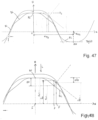
- the base region is designed in such a way that a base line running along the base region from a geometric center of the standing area of a base via a turning point region, in which an orientation of the curvature of the base region (such as a base line mentioned below) changes, to the groove base of the adjacent groove, at a constant distance from the central axis, has a geometric course of height values considered along the central axis as a function of a rotation angle measured in the circumferential direction with respect to the geometric center of the standing area, which angle drops so sharply in an area adjacent to the standing area that a maximum height value assumed in the standing area within a line section of the base line, which takes up at most 30% of a rotation angle between the geometric center of the standing area and the geometric center of the groove base of the adjacent groove, changes by at least 15%, preferably at least 20%, preferably at least 25% and particularly preferably by at least 30% in relation to a height difference of the base line to the angle assumed in the turning point region. Height value is reduced.
- the above-described course of the height values of a floor line applies to any floor line which has a predetermined distance from the central axis which lies between two predetermined, mutually different distance values.
- the two predetermined distance values are larger than the radius of a standing circle of the container.
- the standing circle is in particular the circular ring on which the (circular segment-shaped) standing surfaces of the feet are arranged.
- the curvature region surrounds the flattening region at least substantially halfway around and preferably substantially completely around. This offers the advantage that large amounts of curvature in the flattening region can be avoided.
- the amount of surface curvature within the entire flattened region is smaller than the amount of surface curvature of the curvature region surrounding the flattened region at least halfway and preferably completely.
- the flattening area tapers in the direction of the groove base.
- the flattening area is preferably triangular in shape, with the tip of the triangle pointing in the direction of the base body and/or in the direction of the groove base. This results in a smaller flattening in an area that is less critical with regard to formability and a larger flattening in an area that is more critical with regard to formability.
- the flattened area is essentially flat. It is also conceivable that the flattened area is flat in sections. Preferably, the flattened area is flat in its entirety. A flat design enables good formability.
- the flattened region has a surface area which is at least a quarter, preferably at least a third, preferably at least half of the surface area, preferably at least the same surface area, preferably at least twice and particularly preferably at least three times the surface area of the, in particular substantially flat, standing surface of the standing region of the base for the upright standing of the plastic container.
- the at least three feet each have two flattened areas, in particular symmetrically arranged and/or preferably mirror-symmetrically designed to each other, which in cross-section at least partially (preferably completely within the flattened area) follow the course of the legs of a preferably isosceles triangle.
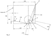
- a distance (a so-called offset) between a tip of the, preferably isosceles, triangle and the base, in particular the base area of the base, is between 0 mm and 20 mm, preferably between 2 mm and 10 mm.
- an opening angle of the triangle which includes the tip of the triangle is between 45° and 170°, preferably between 80° and 150°, preferably between 80° and 120°, preferably between 90° and 120° and particularly preferably between 90° and 110°. Opening angles between 105° and 106° have proven to be particularly advantageous.
- both flattened areas in cross-section follow the course of one leg of the same, preferably isosceles, triangle at least in sections and preferably within the entire flattened area.
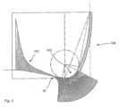
- Such flattened areas are preferably created by using two intersecting planes with an intersection angle that corresponds to the angle at the tip of the triangle considered above (so that the two planes are placed on the legs of the (hypothetical) triangle).
- the two planes are preferably arranged around the base (in the manner or shape of an opened book), as described in the figures.
- the flattening areas can be constructed in such a way that the intersection areas of the feet with the planes are cut off.
- the two levels and/or the triangles are preferably arranged using a guide contour along the base.
- the guide contour is preferably constructed on the middle of a (supporting) foot, particularly preferably with the help of the cutting contour (of the supporting foot and particularly preferably of the supporting area).
- the cutting contour of the supporting foot is preferably used along the geometric center of the supporting area.
- a straight line is used to construct a perpendicular to the radius of the foot.
- the straight line is controlled by an angle.
- the angle is between the perpendicular through the center of the foot radius to the standing surface and the straight line.
- the values are preferably between -30 degrees and 80 degrees, preferably between -10 and 65 degrees.
- a tangent is created perpendicular to the straight line.
- a straight line is created parallel to the tangent at a specified distance as a guide contour.
- the specified distance is between 0 and 20mm, preferably between 2 and 10mm.
- the length of the straight line can be specified.
- An offset curve of the cutting contour of the foot (as a guide contour) is preferably used here. With a preferred distance of 0 to 20 mm, preferably between 0 and 10 mm.
- the length of the offset curve can be determined by determining the starting and end points as a percentage.
- the preferred distance of the offset curve can be from -10 mm to + 20 mm, preferably between 0 and 10 mm.
- the flattened area follows a substantially parabolic course.
- the flattened area follows a branch of a parabola (at least in sections and preferably within the substantially entire flattened area).
- both flattened areas of a seat base follow a substantially parabolic course.
- a cross-section through the seat base and the two flattened areas follows a parabola at least in sections and preferably along the entire flattened areas.
- the parabola for constructing the two flattened areas is arranged on a guide contour.
- the guide contour can be selected according to one of the described embodiments, as described above in connection with a triangle for constructing the flattened areas.
- the base has at least two, in particular symmetrically arranged, flattened areas and the two flattened areas and the base area of the base follow in cross-section at least in sections a course of an open, in particular isosceles, trapezoid.
- a guide contour for the construction of the flattened areas can be selected as described above.
- a base with a preferred base construction from the prior art described below is used to construct the bases with flattened areas.
- the base used for the construction has side flanks, which preferably represent free-form surfaces.
- a construction of a base (with flattened areas) can also be understood as a construction of an inner surface of a blow molding device for producing such a base, which corresponds to the constructed shape of the base.
- a guide contour and at least one, preferably exactly one or exactly two transverse contours are used to construct the base.
- the transverse contour(s) provide(s) a course of at least some sections of the flattened areas produced.
- the transverse contour can be described by the following preferred variants.
- the height is preferably defined between 2 and 50 mm.
- the short side of the trapezoid pointing downwards towards the standing surface and/or standing area.
- the length of the short side of the trapezoid is preferably between 0.5 mm and 10 mm.
- the interior angles are preferably the same size.
- the interior angle is preferably between 91 and 170 degrees, preferably between 95 and 155 degrees.
- the vertex is on the guide contour.
- y ax ⁇ 2+bx+c
- the parameter a is greater than 0, preferably the parameter b is greater than 0 and the parameter c is preferably between -10 and 10mm, preferably between -5mm and 5mm.
- the guide contour can preferably be realized by the two options described above as variant A and variant B.
- Another preferred transverse contour can also be described by a polynomial of nth degree, where the value of n can range between 2 and 7.
- An offset curve is understood in particular to be a spline with a polynomial of the nth order, where the value of n can range between 2 and 7.
- foot side regions of the base are designed in sections as foot flank surfaces formed by a free-form surface, wherein the foot side regions are preferably designed as free-form surfaces substantially completely outside the curvature region.
- the foot flank surface is preferably designed as a free-form surface, which is preferably connected to the surface edges of the base and/or a foot area and in particular to the surface edges of the base body (and in particular a central area and/or an injection point) in a particularly tangentially continuous and preferably curvature-continuous manner.
- the free-form surface is in particular a surface whose curvature in one (any) direction can be described by polynomials of the nth degree.
- a tension band arranged in the base area of a container, in particular between the feet, serves to direct forces acting on the base center or the base center - such as an injection point of a plastic container - via the tension band to a side wall of the plastic container.
- a groove can be understood as a geometric structure which extends inwards (in particular in the direction of the container mouth and/or the central axis) with respect to the (surrounding) (outer) wall of the container, i.e. the (outer) wall of the base area, in particular with respect to a normal level of the peripheral wall.
- the groove is preferably the area between two turning point areas which extend around a turning point circumferential angle as described above.
- groove base can be understood as a (partial) area of a groove which differs from at least one other area and in particular from the remaining area of the groove and/or from a foot flank surface of a base due to its (uniform or common) geometric construction, such as uniform parameters of a surface parameterization and/or selection of a surface (or a common rule for the surface construction).
- the groove base can be understood to mean the (in particular contiguous) area of a groove that essentially forms the (furthest) inwardly extending (minimum) area (and the area surrounding this).
- the groove base preferably differs from the rest of the groove in that it has been constructed according to a different surface shape compared to the rest of the groove and in particular to an area of the groove arranged laterally adjacent to the groove base, which lies between the groove base and the base.
- the area described above, arranged adjacent to the groove base and lying between the groove base and the base (in its entirety) is part of a foot flank surface of a base (and in particular is constructed accordingly as such).
- the base body preferably serves to accommodate the essential filling volume (of a beverage).
- the base body has a (side) wall that runs completely around the circumference.
- the base body can have a substantially circular (preferably circular) cross-section (with a predetermined main diameter, cross-section when cut in a plane perpendicular to the central axis).
- the (in particular each) groove base (or a drawstring), in particular each, has two lateral drawstring areas in which the wall of the container (in particular the base area) is curved outwards, and a central drawstring area which is arranged in the circumferential direction between the two lateral drawstring areas, wherein in the central drawstring area the wall of the container is curved inwards.
- the two lateral drawstring areas and the central drawstring area arranged (in the circumferential direction) between the two lateral drawstring areas are arranged between two (adjacent) feet.
- the surface of the central drawstring area is curved in particular towards the inside of the container or towards the inside of the bottle.
- the two lateral tension band areas each form an outer tension band area (seen in the circumferential direction) and/or an outer groove base area.
- the (in particular each) groove base or the (in particular each) tension band (seen in and/or against the circumferential direction) is delimited by one of the two lateral tension band areas (in the direction of an adjacent base).
- the wall of the container in the base area is, in particular, at least partially curved inwards in a central area (the central drawstring area) of the groove base of a groove and curved outwards in the two edge areas of the groove base adjacent to the central area of the groove base (in particular the lateral drawstring areas).
- the present invention offers the advantage that the curvature towards the inside (of the bottle) causes the drawstring to fit better into the base geometry. This makes it easier to stretch the material into the feet or legs. This preferably prevents the formation of distortions and increases stability. Furthermore, the blowability and moldability are improved.
- the base region in the middle tension band region has a concavely curved or concavely arched outer surface of the container.
- a concave curvature or concave arch is present essentially along the entire line section between the injection point and/or between a central region around the injection point and the boundary of the base region towards the base body.
- the base region (in each case) in the lateral drawstring region has a convexly curved or convexly arched container outer surface.
- such a convex curvature or convex arch is present essentially along the entire line section between the injection point and/or between a central region around the injection point and the boundary of the base region towards the base body.
- a base contour of the base area of the container in the standing area (in particular in the entire standing area) of a base can be described by a base contour in this base area, which preferably initially has a straight section (in particular starting from a geometric center of the container and/or an injection point and/or a central section), to which a spline or curved section is connected.
- This curved section is preferably followed by a further curved section or spline, as well as preferably a further curved section with which the base area merges into the base body.
- the standing area or the foot surface, in particular the base and/or the standing area is preferably generated from this base contour by rotating the base contour around the central axis of the container selected as the axis of rotation.
- the groove base and/or the central tension band region and/or the two lateral tension band regions extend from the injection point or a central region surrounding it in a radial direction outwards (following the course of the bottom wall in the longitudinal direction), essentially up to (or almost up to) the base body.
- the groove and/or the groove base and/or the central tension band region and/or the two lateral tension band regions extend over at least 75%, preferably at least 80% and particularly preferably at least 90% of the arc length of a line starting from the injection point and/or the central region and formed from there on the bottom wall in a radial direction outwards to the base body.
- the groove and/or its groove base (and in particular at least one arranged groove and/or its groove base extends between two feet) in the radial direction (at least with one component).
- the main extension direction of the groove and/or the groove base runs in a projection of the groove or the groove base onto a plane perpendicular to the longitudinal axis essentially and in particular exactly along a radial direction.
- At least one and preferably exactly one groove is arranged between each two adjacent feet (laterally or in the circumferential direction), wherein the respective groove preferably has a main extension direction running in the radial direction (wherein in particular at least one component of the main extension direction points in a radial direction).
- a (each) groove base extends substantially along each bottom height section of the groove base (wherein a bottom height of a section is measured in the longitudinal direction with a standing plane on which the container stands as a reference plane), in particular substantially over the same (predetermined) circumferential angle.
- a region of the groove base closer to the standing surface extends substantially over the same (predetermined) circumferential angle as a region of the groove base closer (seen in the longitudinal direction) to the base body and/or the mouth region.
- a projection of the groove base and/or a projection of the central tension band region and/or a projection of the (in particular respective) lateral tension band region (opposite the longitudinal direction) onto a standing plane of the container (which is arranged perpendicular to the longitudinal direction) occupies a segment of the respective projection surface (of the base region) that can be defined and/or described essentially by a circumferential angle.
- a groove base is arranged substantially and preferably exactly symmetrically (relative to the circumferential direction) between two (adjacent) feet.
- a (each) groove and/or a (each) groove base is (axially) symmetrical with respect to a plane which extends in the longitudinal direction of the central axis or longitudinal direction of the container and in a (radial) direction along the geometric center (seen in the circumferential direction) of the groove and/or the groove base.
- the line section at the geometric center of a groove base is closest to the central axis.
- this line running (exclusively) along the circumferential direction has an inward curvature in the area of the groove base, at least in sections and preferably in the entire area of the groove base.
- a section of the base region is formed with a plane which is perpendicular to the central axis, this is curved inwards in the area of the groove base (in particular in this entire area) (towards the central axis).
- a turning area in which this curvature or curvature reverses and/or changes its orientation is located (exclusively) outside the groove base.
- the middle tension band region extends at least in sections along the geometric center of the groove base and is preferably designed symmetrically with respect to the geometric center.
- the wall of the container is curved inwards at least in sections and preferably essentially along the geometric center of the groove base (in particular when looking at a main direction of the surface, which corresponds to a circumferential direction). This results in a particularly stable base geometry due to the symmetrical arrangement.
- the groove base has at least a first and a second turning area, in which a surface area of the groove base changes the orientation of its curvature.
- a surface area of the groove base changes the orientation of its curvature.
- the orientation of the first lateral tension band area (an outward curvature) changes to the orientation of the middle tension band area (an inward curvature).
- the orientation of the middle tension band area (inward curvature) changes to the orientation of the second lateral tension band area (outward curvature).
- At least one (in particular each) line running on the surface of the base region in the groove base, which extends along the circumferential direction (which in particular does not extend along the longitudinal direction), has a first turning region in which a surface region of the groove base changes the orientation of its curvature and is in particular transferred from an outwardly curved region to an inwardly curved region.
- the line has a second turning region in which a surface region of the groove base changes the orientation of its curvature and is in particular transferred from an inwardly curved region to an outwardly curved region.
- the tension band and/or the groove base is a rotated surface, i.e. a surface which is created by rotation (of a tension band contour extending in particular in a longitudinal sectional plane through the central axis) in the circumferential direction around the central axis (around the groove base circumferential angle).
- the tension band (which is particularly realized by the groove base) is a free-form floor section.
- the tension band is replaced by a free-form surface.
- a free-form cut makes it possible to distribute the material more precisely within the tension band. In particular, this also makes it possible to avoid (visible) distortions that can lead to the weakening of the tension band. This increases the stability of the floor.
- Freeform surfaces are understood to be three-dimensional, usually doubly curved surfaces, which can preferably (in particular only) be mathematically represented by splines (piecewise polynomial functions) and/or by means of NURBS (Non-Uniform Rational B-Spline).
- the tension band or the groove base is designed as a free-form surface which is connected to the surface edges of a foot flank surface or a transition area, the is arranged laterally on a base and is connected to the base body of the container and to a central area around an injection point or to the injection point in a particularly tangentially continuous and in particular curvature-continuous manner.
- the curvature of the free-form surface of the groove base in a (any) given direction can be described by polynomials of the nth degree.
- At least one, preferably at least two, preferably at least three parameters characteristic of the free-form surface of the groove base are selected and/or determined, for example approximated, in such a way that the free-form surface is approximated in its geometric shape to an area of a spherical surface and in particular is designed in the manner of a hemispherical (segment).
- a groove base cross-sectional contour in a cross-section perpendicular to the longitudinal direction of the container follows at least in sections and preferably essentially completely an nth degree spline, which deviates from a circular course at least in sections, particularly in the middle drawstring area and/or the two lateral drawstring areas.
- At least one groove (preferably each groove) (preferably between two feet) has a groove circumferential angle which is between 10° and 60°, preferably between 20° and 50°, preferably between 30° and 38° and particularly preferably 34°.
- At least one groove base (preferably each groove base of each groove between two feet) extends over a groove base circumferential angle that is between 2.5° and 10°, preferably between 3° and 7°, preferably between 4° and 6° and particularly preferably 5°. This makes it possible to achieve a sufficiently functional tension band.
- a groove base (preferably each groove base) of a groove between two feet essentially occupies exactly one extension in the circumferential direction, which corresponds to a Angle segment over the specified groove base circumferential angle.
- a groove base in particular extends along its entire extent along the longitudinal direction over the (essentially exactly over) the specified groove base circumferential angle.
- a groove (preferably every groove) between two feet essentially takes up exactly one extension in the circumferential direction, which corresponds to an angle segment over the predetermined groove circumferential angle.
- a groove base in particular thus extends along its entire extension along the longitudinal direction over the (essentially exactly over) predetermined groove circumferential angle.
- the groove base and/or the groove is designed essentially symmetrically to the geometric center of the groove base.
- the symmetrical design results in a particularly stable base geometry.
- an area of the base section arranged between a base and a groove base merges into the groove base with a continuous tangent and/or curvature. This also results in particularly good stretching of the material into the tips of the bases.
- the groove base of (each) groove merges into the remaining region of the groove (and/or into a standing region) and/or into a foot flank surface (of a foot) in a region whose main extension direction extends (essentially exclusively) in the radial direction on the base region wall and in particular not in the circumferential direction.
- the transition region from a groove base of (each) groove into the remaining region of the groove and/or into a foot flank surface (of a base) is defined by a line formed on the base region, which extends along the base region (essentially exclusively) in a radial direction and not in a circumferential direction.
- one (preferably each) area of the base section arranged between a base and a groove base is tangentially continuous and/or curvature-continuously into the groove base.
- a region of the base section (in particular a foot flank surface) arranged laterally adjacent to the groove base (seen in the circumferential direction) (in particular each region) merges into the groove base in a tangentially continuous and/or curvature-continuously.
- the tangent continuity or curvature continuity is seen in particular when considering a transition in the circumferential direction and/or along a base line and/or when viewed radially.
- the groove base follows a circular spherical course at least in sections (preferably at least the area of the groove base arranged between two feet in the circumferential direction) and in particular essentially along its entire extension in the radial direction.
- the base area between each two (adjacent) feet has an area (extending essentially from a central area and/or injection point to the base body of the container) which has a circular spherical (segment)-like course.
- the groove base deviates from a (substantially) exact hemispherical (segmental) wall section or profile at least in sections and in particular in one (each) area between two feet (seen in the circumferential direction).
- a (substantially) exact hemispherical (segmental) wall section or profile at least in sections and in particular in one (each) area between two feet (seen in the circumferential direction).
- no area of the groove base follows a strictly geometric hemispherical (segmental) profile.
- a hemispherical shape of an area is understood to mean in particular that this area does not exceed 20%, preferably not exceed 10%, preferably not exceed 5% and particularly preferably not more than 2.5% of a sphere radius deviates from a sphere approximated to the area (in particular in the radial direction relative to the sphere center of the approximated sphere).
- a line formed along the geometric center between two adjacent feet and/or the geometric center of the groove and/or the geometric center of the groove base on the wall deviates from a circular arc approximated thereto at least in sections (at each point of the formed line) by less than 20%, preferably less than 10%, preferably less than 5% and particularly preferably less than 2.5% of the circular radius of the approximated circular line with respect to a geometric distance of this formed line from the approximated circular line.
- the line formed preferably takes up more than 20%, preferably more than 30%, preferably more than 40%, preferably more than 50%, preferably more than 60%, preferably more than 70%, preferably more than 80% and particularly preferably more than 85% of the arc length of a connecting line formed on the wall, running through the geometric center between two adjacent feet and/or through the geometric center of the groove and/or the groove base, between the center of the base and/or the injection point on the one hand and the transition of the base area into the base body on the other.
- This line formed can preferably be described (at least in sections and preferably in an area of more than 85% of the arc length) by a spline of the nth degree. However, it is also conceivable that this line formed can be described by a circular line.
- the groove base (or the drawstring) is not a surface that is rotationally symmetrical about the central axis of the container (in particular in its entirety and preferably also not at least in sections).
- a deviation from a rotationally symmetrical surface section offers the advantage that it enables adaptation to the curve (particularly with regard to the curvature) while at the same time maintaining a largely hemispherical segment-shaped form.
- the mouth region preferably has an external thread and/or a support ring.
- the base region preferably has an injection point located in particular on the central axis and the base region preferably has a central region surrounding this injection point, in particular one that is rotationally symmetrical.
- the injection point is preferably located above the feet of the container when viewed in the longitudinal direction (when the container is standing upright).
- the feet or outer surfaces thereof form a particularly flat standing section of the plastic container, in particular extending (exclusively) in a plane perpendicular to the longitudinal direction, preferably at least partially in the form of a ring segment, extending over a predetermined circumferential angle.
- the container preferably has a filling volume (of a beverage) of at least 0.1 l, preferably at least 0.2 l, preferably at least 0.3 l, preferably at least 1 l, preferably at least 1.5 l, preferably at least 2 l, preferably at least 3.5 l and in particular at least 5 l.
- the container preferably has a maximum filling volume of 5 l, preferably 3.5 l, preferably 2 l, preferably 1.5 l, preferably 1 l.
- the container preferably has a filling volume in a range between 2 l and 3.5 l.
- the container is preferably suitable for carbonated drinks.
- the base region preferably has more than three, preferably more than four, preferably more than five and particularly preferably more than seven feet.
- the base region preferably has fewer than ten, preferably fewer than eight, preferably fewer than six and particularly preferably fewer than four feet.
- the container preferably has a petaloid base.
- the container bottom has a discrete axial symmetry with respect to the central axis.
- the container base has a substantially constant wall thickness at least in sections and preferably over the entire surface.
- a wall thickness in the area of a base and the area of a groove base is substantially the same. This advantageously makes it possible to achieve the greatest possible stability of the container or container base with the least possible use of material.
- the present invention is further directed to a blow molding device for producing, in particular a base region, plastic containers with an inner wall against which a plastic container (preferably produced from a plastic preform by blow molding) can be expanded during a blow molding process.
- the inner wall has a contour which is suitable and intended to produce a plastic container, wherein the plastic container can be designed with all the features described above in connection with the plastic container alone or in combination with one another.
- the blow molding device has a base part or is designed (exclusively) as a base part which is suitable and intended to produce a base region of the type described above.
- the base part is preferably used to form a cavity (in the assembled state or in the operating state) with at least two blow mold side parts, within which plastic preforms can be formed into the plastic containers by exposure to a flowable (preferably gaseous) medium, wherein an inner wall of the blow mold side parts and the base part delimiting the cavity has a contour which produces a predetermined shape of the containers to be produced.
- the blow molding device can also have (blow molding) side parts (which can preferably be detachably connected to the base part).
- the blow molding device preferably has a plurality of openings, in particular for venting the blow molding device.
- the openings provided in particular for venting enable a fluid and preferably gaseous medium to be discharged during an expansion process of the plastic container.
- the blow molding device has at least one base formation region for producing a base of the plastic container, wherein the inner wall and/or the inner contour of the blow molding device in the region of the base formation region has at least one flattening region and preferably two flattening regions.
- each base formation region of the blow molding device designed to form a base has at least one opening (in particular for venting the blow molding device) and preferably a plurality of openings (in particular for venting the blow molding device) provided in particular for venting the blow molding device, wherein the at least one opening is arranged at least partially and preferably completely in the flattening region of the blow mold.
- a combination of the opening with the design of the container or the base shape with a flattened area (in the corner area of the base) advantageously ensures that in particular the corner areas of the base, which in the prior art could only be produced in a sufficiently high quality using high finishing blowing pressure, can now be produced using a significantly lower finishing blowing pressure, with equally high-quality results.
- a ratio between a surface of the base part and a surface of the (preferably all openings (in particular arranged in the base part) provided for venting the blow molding device) is 3 - 350, preferably 4 - 200 and particularly preferably 5 - 100.
- the ratio between a surface of the base part and a surface of the openings is 25 - 180, preferably 35 - 175 and particularly preferably 47 - 169.
- the preferred or advantageous ratio depends in particular on the size of the bottle or the bottle volume and the shape of the openings.
- a ratio between a surface of the base part and a surface of the openings, which are preferably holes or bores, of 169 is preferred.
- the ratio between a surface of the base part and a surface of the openings is advantageously 145 - 180, preferably 150 - 175 and particularly preferably 155 - 173.
- the ratio between the surfaces of the openings and the base part is always approximately the same, regardless of the diameter of the base part, i.e. that with a larger diameter, the surface area occupied by the openings is correspondingly larger. This can be achieved, for example, by having more openings or larger openings compared to a smaller diameter of the base part. This ensures sufficient venting for any blow mold or container size.
- the surface area of the openings is understood to be the area which the openings in the form of holes, slots or other shapes occupy or have on the base part.
- the applicant's internal investigations and tests have shown that, based on this example, a plastic container with a diameter of 65 mm achieved very good finished blow molding pressure results. It is therefore preferable to adjust the ratio between the surface area of the base geometry and the surface area of the vent openings for a test container with a diameter of 100 mm to the ratio of the container diameter of 65 mm.
- the surface area of the (vent) openings of this container is preferably essentially 0.000094 m 2 (94 mm 2 ).
- the holes or openings are preferably designed in such a way that they are large enough to allow ventilation or a sufficiently large flow cross-section, but still small enough so that no material from the plastic container is pressed into the openings during forming and no visible and/or noticeable areas are formed on the finished plastic container.
- the openings preferably open into channels which extend through the wall of the blow mold and the base part, so that the flowable medium is preferably discharged from the blow mold via the channels.
- the openings within a wall of the blow mold parts and in particular the base part are preferably connected to channels which serve to discharge the gaseous medium.
- These channels advantageously extend at least partially through the wall of the base part.
- the channels preferably establish a flow connection between an outer wall of the base part and an inner wall of the base part and thus preferably also between an interior of the blow mold and an exterior of the blow mold.
- a (particularly maximum) diameter of the base part or the blow molding device is between 50 mm and 200 mm and the surface of the openings is between 23 mm2 and 500 mm2 and/or the surface of the base part is between 3900 mm2 and 65000 mm2 and the surface of the openings is between 23 mm2 and 500 mm2.
- Combinations of diameter of the base part, surface of the openings and surface of the base part are advantageous, which result in a ratio between surface of the openings and surface of the base part of preferably 160 - 175 and particularly preferably almost 169, since such a ratio results in the lowest compressed air consumption. with the highest possible container quality. This ratio is particularly advantageous for bottle volumes of 0.5 l and the design of the openings as holes.
- the openings are a plurality of holes and/or slots arranged in the base part and in particular in the areas of the base part which serve to form the standing areas of the finished container.
- a combination of slots and holes is also preferred.
- the openings are designed as slots, for example, a ratio of 169 still provides satisfactory results, but the bottle quality can be further advantageously improved with a ratio of up to 47, so that the ratio between the surface of the openings and the surface of the base part, when the openings are designed as slots, is preferably 40 - 180, preferably 45 - 170 and particularly preferably 47 - 169.
- the ratio between the surface of the openings and the surface of the base part is preferably 30 - 50, preferably 33 - 45 and particularly preferably 35 - 41.
- the holes can preferably be arranged in an orderly manner along at least one and preferably at least two imaginary geometric lines.
- a disordered arrangement of the holes is also conceivable, for example specifically in areas in which the standing areas of the container can be difficult to form, such as very narrow or small areas.
- a slot can also be formed by an arrangement of a plurality of holes or bores, which are preferably arranged along a row or a spline.
- a plurality of holes preferably extends along at least one geometric line.
- the holes are arranged along two or more rows next to each other, so that at least two rows of holes extend next to each other along geometric lines.
- the number of holes of the ventilation bores in the base part is preferably again dependent on the required or desired vent hole surface in relation to the surface of the base part.
- the openings and/or holes are arranged in three rows.
- the holes in the individual rows can preferably be arranged directly next to each other at the same height or offset from each other.
- the holes preferably have a diameter of preferably 0.2 mm to 7 mm, preferably 0.3 mm to 5 mm and particularly preferably 0.5 mm to 4 mm.
- the distances between the individual holes in a row are preferably the same or different. The distance is preferably 0.6x to 2.5x the diameter of the holes and particularly preferably 0.5x to 2x the diameter of the holes.
- the openings and in particular the plurality of holes arranged along a row are preferably guided within a channel in order to remove the gaseous medium more quickly from the base mold.
- the channel preferably has a width multiple of the diameter of the holes.
- each section of a base part has a specific drilling pattern.
- the drilling pattern in a foot and/or a section of the base part can preferably consist of an arrangement of several rows and columns.
- the drilling pattern is arranged centrally within the section of the base part.
- the holes or vent holes preferably all have the same diameter or different diameters. If the diameters are different, the diameters are preferably in a ratio of between 0.25 and 10, preferably between 0.4 and 8 and particularly preferably between 0.5 and 6 to one another.
- the number of holes of the vent holes in the base part is preferably dependent on the required or desired vent hole surface in relation to the surface of the base part.
- the base part is designed to form feet of the plastic container, each foot having a plurality of openings.
- the base part is designed to form feet of the plastic container, each foot having a plurality of openings.
- three to twelve support areas are arranged in the base part to form three to twelve feet of the plastic container.
- the openings are therefore preferably arranged in an area of the base part which serves to form standing areas of the container.
- the openings are therefore preferably arranged in curved sections of the base part.
- each base or each area of the base part used to form base areas of the container has 7 - 35 openings, preferably 8 - 30 openings and particularly preferably 10 - 25 openings.
- a base part with five base areas therefore has 35 - 175 openings, preferably 40 - 150 openings and particularly preferably 50 - 125 openings.
- At least one hole has a diameter of between 0.5 mm and 4 mm, preferably between 0.8 mm and 2 mm.
- the diameters of the openings should particularly preferably be no larger than 2 mm and no smaller than 0.8 mm. In other places, the openings can preferably be up to 5 mm in size in order to achieve rapid venting.
- a distance between two openings arranged next to each other is less than 4 mm, preferably less than 3 mm and preferably less than 2 mm.
- the minimum distance between two bores, from bore edge to bore edge, is preferably 0.2 mm.
- the distance between two openings and in particular holes arranged next to each other is therefore preferably between 0.5 mm and 4 mm, preferably between 0.4 mm and 3 mm and particularly preferably between 0.2 mm and 2 mm.
- each standing area or each area of the base part which serves to form standing areas of the plastic container has between one and four slots.
- the at least one opening arranged in the flattening region of the base formation region has a larger surface or a larger opening diameter, preferably twice as large and particularly preferably three times as large a surface and/or opening diameter (and/or flow cross-section) than the openings arranged outside the flattening region.
- the flattening region of the base formation region has exactly one opening. This advantageously takes into account the fact that this region of the base is not formed as quickly as the other regions of the base during the blow molding process of the container. This makes it possible to achieve a particularly high quality of formation of the base region.
- the base formation region preferably has a curvature region which has an inner surface or contour corresponding to the above-described curvature region of the base of the plastic container (in particular according to a preferred embodiment).
- at least one, preferably exactly one opening is arranged in the curvature region.
- the opening arranged in the curvature region is arranged between the opening in the flattening region and a bottom center of the blow molding device (for producing the bottom center of the plastic preform) when viewed in the radial direction (and/or along a shortest connecting line along the contour of the blow molding device).
- two openings are arranged in each case in the region of the blow molding device corresponding to the base region.
- an opening designed as a slot can open into the essentially circular opening arranged in the flattened region.
- the (in particular each) base formation region has a plurality, preferably more than 5, preferably more than 10, openings per side of the base.
- the plurality of openings are preferably each arranged in a base formation region which is designed to correspond to a region of the base arranged in or against the circumferential direction next to the base region of the base.
- the plurality of openings can be arranged in (essentially) within a common plane.
- the plurality of openings can be all openings on one side of a base formation area which is arranged radially further outward than the flattened area and/or the curved area in relation to the central axis of the blow molding device or the plastic container to be produced therein.
- the plurality of openings may be arranged in the form of one, two, three or more rows, each row being formed by a plurality of openings.
- Each row can follow an essentially straight line (e.g. along a common plane) or a curved line.
- Figure 1 shows a schematic representation of a plastic container 1.
- This plastic container has a mouth area 6 with a container mouth 8 and a base body 50 adjoining the mouth area 6.
- the base body 50 serves to accommodate the essential filling volume.
- the shape of the base body can also be different from that in Figure 1 shown and can, for example, create waves or pattern.
- the mouth region 6 can have an external thread of the plastic container 1 and a support ring located on the container mouth 8.
- the container according to the invention also preferably has an external thread and a support ring.
- the reference symbol L indicates a longitudinal direction of the plastic container 1. As shown, this is the longitudinal direction L and a direction along the central axis M of the container. In addition, Figure 1 a circumferential direction U is shown, which is a direction of rotation around the central axis or the longitudinal direction L as the axis of rotation.
- a base region 2 of the plastic container 1 adjoins the base body 50, wherein the base body 50 can merge into the base region 2 via a curved section or via a non-curved section.
- the reference number 22 indicates a base (not shown here) of the container (see e.g. Fig. 2 ).
- the base area 2 can have several feet 22 with which it can stand upright on a flat surface.
- the reference symbol R refers to a radial direction in relation to the central axis M or the longitudinal direction L of the plastic container.
- the radial direction R is perpendicular to the central axis M and the longitudinal direction L and either runs towards them or away from them to the outside.
- the base body 50 is formed in particular by a side wall or has such a side wall. This side wall runs completely in the circumferential direction U of the container.
- Fig. 2 shows a representation of a preferred floor section in the area of a stand 22. More specifically, the Fig. 2 The line shown in the figure shows the course in the area of the base. The base contour in this base area is initially described by a straight line 101, which is followed by a spline or curved section 102. This curved section 102 is followed by another curved section or spline 103 and another curved section 104, with which the base section merges into the base body 14. From this in Fig. 2 The contour shown can be changed by rotating the floor geometry around the Rotation axis M (which also defines the geometric center of the floor section) can be generated.
- Rotation axis M which also defines the geometric center of the floor section
- the transitions from the straight section 101 to the curved section 102 at point F and/or the transition from the curved section 102 to the foot radius 103 to the point E shown are preferably tangent-continuous.
- the position of point E can be controlled via the angle 110 on the foot radius of section 103.
- the transition to the curved section or spline 104 is preferably tangent-continuous, particularly preferably curvature-continuous.
- the curved section 104 preferably transitions tangent-continuous and particularly preferably curvature-continuous into the base body or the outer diameter of the container.
- the curvature of this curved section 104 can be described by a polynomial of the nth degree.
- the outer dimensions of the base section are determined by the outer diameter or radius 105 and the base height 106.
- the dimension of the standing circle diameter or radius 107 is preferably determined by a ratio to the outer diameter 105.
- the height of the straight line 108 is preferably described by a ratio to the outer diameter 105.
- the starting point D of the curved course 104 is generated here by a straight line between the point B and the point C.
- This straight line BC is advantageously arranged tangentially to the foot radius.
- the starting point D of the curved section 103 can in turn be determined using the angle 109 on the foot radius of the section 103 between the points A and C.
- Fig. 3 shows a curve of the curvature of the Fig. 2 shown section. It can be seen that the area 102 is curved in a first direction and the area 103 in a second direction. Between these two areas there is an inflection point W in which the curvature changes. It can also be seen that the curvature in the area 103 is stronger than in the area 104.
- the respective straight lines extending perpendicular to the line give a measure of the inverse curvature, that is, the longer the respective lines, the larger the radius of curvature and the smaller the curvature.
- the entire course of the floor section resulting from sections 102, 103 and 104 has only one turning point.
- Fig. 4 shows a preferred course in the area of a groove base 62 or tension band.
- the contour is again initially described by a straight line 114 and the adjoining large tension band radius 111, an area that preferably has a constant curvature.
- This area 111 is followed by an area 112 with a smaller tension band radius.
- This area in turn is followed by a section 113 in which the course can also be straight.
- This area 113 in turn is followed by the base contour of the foot and the transition into the base body.
- the tension band surface is also generated from this contour shown, as shown in more detail below, by a rotation about the axis of rotation M.
- the transitions between the area 111, the area 112, the section 113 and the base contour 104 are advantageously continuous in tangency.
- the Fig. 5 to 10 show a base region 2 of a plastic container 1 according to an embodiment from the prior art, each with curvature profiles KV shown along different intersection curves. In each case, this is the same base region 2 designed as a petaloid base, which is used for carbonated drinks, for example.
- the base area shown here as an example has five feet 22, each of which has a base area 24 extending essentially from the base center 18 to the boundary of the base area to the base body.
- the base area 24 has a base surface 23, in particular one that is essentially flat, which forms a base plane on which the plastic container 1 stands upright on its feet 22.
- the base center (typically an injection point of the plastic container 1) is spaced from the standing level by a so-called ground clearance.
- a groove 30 is arranged, in which the base area 2 extends comparatively further towards the interior of the container.
- Fig. 5 also that the bottom area 2 in the groove (at least in sections) is curved inwards or concavely curved, while the bottom area (except in an area around the bottom center 18, (in particular in both main curvature directions) is curved outwards or convexly curved.
- an inflection point region (indicated by the reference symbol W in the following figures) in which the orientation of the curvature of the base region is reversed (at least in one main curvature direction).
- the reference number 32 designates a groove base of the groove 30, which is arranged in the geometric center of the groove and which is designed in such a way that it acts as a tension band, which transfers forces acting on the base center 18 to the base body.
- the base body preferably has an essentially hemispherical (or ellipsoidal) shape (within an angle segment defined in the circumferential direction).
- the reference number 26 designates a foot side region 26, which represents a lateral region of the base 22. This is in particular mainly directed towards the adjacent base 22. A main extension direction of the respective normal vector of surface points of this foot side region 26 runs in (or against) the circumferential direction U.
- the reference symbol E designates a corner area of the base 22.
- an outer base area 28, a (in the radial direction) (mainly) outward facing area, and a (in the upright position on the bases) (mainly) downward facing base area 27 meet.
- This corner area is arranged between the base side area 26 and the base area.
- the corner area serves as a kind of transition area of the base area 24 in the foot side area 26.
- the corner area E serves to transfer the foot outer area 28 into the foot side area 26.
- a preferred example of a plastic container with a bottom region 2 according to the Figures 5-10 could have a diameter of 100 mm.
- the standing circle diameter could be 64.5 mm.
- the ground clearance, measured from a contact surface/standing plane to the ground center/injection point, is 5.507 mm in this example.
- Identical reference symbols subsequently identify identical or similarly acting and/or designed areas or features.
- the Figures 5 and 6 show the curvature KV of the base area along a longitudinal section contour LK, which results from a longitudinal section of the base area 2 through the corner area E, whereby the longitudinal section is made along a plane in which the central axis M lies.
- the longitudinal section contour LK has no extension in the circumferential direction U.
- the curvature along this longitudinal section contour shows that the base area is curved inwards in an area around the injection point or the base center 18. Further outwards radially, i.e. with increasing distance from the central axis M, the orientation of the curvature reverses to an outward-curved or convex curvature.
- the base area is convexly curved along the longitudinal section contour. The amount of curvature increases sharply in the area of the corner area E and initially falls slightly in the corner area and then rapidly after the corner area.
- the base area along the longitudinal section contour LK only has a slight (convex) curvature.
- the curvature amount and/or the curvature value decreases continuously, but compared to the adjacent regions, the longitudinal section contour does not have a local minimum of the curvature amount and/or curvature value in a section lying within the corner region E.
- FIGS. 7 and 8 show the curvature along a floor line BL through the corner area E and the base area 24 of a base 22.
- a floor line here (and below) is understood to mean a contour resulting from a cylindrical intersection with the base area or a line following this contour on the outer surface.
- the ground line represents a circular line.
- the floor line describes a line following the floor area (or its outer surface), which always has the same distance from the central axis.
- the curvature of the base line refers (also below) in particular (also below) to the base line BL developed (along the cylinder surface), so that the curvature shown exclusively represents a curvature of the height values of the base area as a function of a circumferential angle (measured in the circumferential direction).
- the height values are measured (exclusively) along the central axis by projecting the respective point of the ground line in an exclusively radial direction onto the central axis.
- the height values are measured as the distance of the respective point of the bottom line to a plane running perpendicular to the central axis, which, for example, passes through the container area in which the bottom area merges into and/or borders on the base body.
- the ground area along the standing area 24 is uncurved (has the same height value and moves along a circular line).
- the ground line BL runs accordingly on a circular line within the standing area 24.
- the turning point WP represents the boundary between the groove region 30 and the base 22.
- FIGS. 9 and 10 Two slightly different perspective views each show the floor area with a floor line BL, which also runs through the corner area E and the stand area 24, but here additionally through the stand area 23.
- this bottom line (in the projection described above) has a circular diameter of 64.50 mm.
- the floor line BL running through the base 23 shows a similar curvature behaviour as the Figures 7 and 8 selected floor line BL.
- curvature value is zero
- the amount of the curvature value or the curvature value increases until a (precisely one) maximum value MW is reached within the corner area E and then decreases steadily until the turning point WP is reached (curvature value is zero here).
- the turning point WP represents the boundary between the base 22 and the groove 30.
- the amount of the curvature value increases steadily until a maximum amount of curvature is reached (minimum curvature value, since curvature values are negative) and following the base line further in the direction of the groove base 32, the amount of the curvature value decreases steadily again.
- a sudden drop in the amount of the curvature value at the transition to the groove base 32 is conceivable. It is conceivable, as in the Figures 7-9 shown, a groove base which has a non-curved bottom line within the groove base. However, other embodiments of a groove base are also conceivable, for example with different inward and outward curved areas.
- the two laterally arranged corner areas E of the feet 22 represent the most challenging area in the blow molding process. Good moldability can only be achieved with this base design by applying a very high final blowing pressure.
- Fig. 11 to 13 each show an illustration of a construction of a stand 22 proposed according to the invention ( Figures 11, 12 ) and a resulting floor area 2 ( Fig. 12 ) with several feet 22 according to the invention according to a preferred embodiment. Both figures show a view from the outside of the centrally shown foot 22 in different perspective views.
- the previous floor profile of the base 22 is flattened in the two corner areas E of the base 22 arranged laterally to the stand area or the stand surface 24 by providing a flattening area 40 in each case.
- this flattened area 40 is flat.
- a curved area 42 is provided around the flattened area 40, which transfers the floor profile of the standing area into the floor area of the groove or the remaining foot side surface 26.
- Fig. 13 compares the previous floor profile of a stand with the modified embodiment of a floor profile of a stand 22 according to the invention.
- the reference numeral 34 designates the geometric center of the groove base 32, which usually also forms the geometric center of the groove 30.
- the two Figures 11 and 12 illustrate a construction of the flattening area 40.
- all other areas of a (petaloid) base known from the prior art remain, in particular the Figures 5-10 described and illustrated soil areas 2, unchanged.
- a transverse contour is preferably used for the construction, which here is given by an isosceles triangle with tip S and the two legs DS (described above as variant Z).
- the opening angle of the triangle at tip S can be between 45° and 179°, preferably between 80° and 150°. In the example shown, the opening angle is 105°.
- the height (of tip S above the standing area) is preferably between 2 and 50 mm.
- the guide contour preferably runs in a plane in which the geometric center of the base area 24 and/or the base 22 runs. In Figure 11 the guide contour runs through the tip of the triangle S and is perpendicular to the figure plane.
- variants A or B described above can be used as guide contours.
- the guide contour is preferably constructed on the middle of a foot, particularly preferably with the help of the cutting contour.
- a perpendicular is constructed on the radius FR of the (standing) foot 22 using a straight line.
- the reference symbol FM indicates a center point of the circle with radius FR, which a cross-sectional contour of the foot follows at least in sections.
- the straight line is controlled by an angle. The angle moves between the perpendicular through the center of the foot radius to the standing surface and the straight line.
- the values are between -30° and 80°, preferably between -10° and 65°.
- the reference symbol FG indicates a straight line that runs along a radius FR.
- the straight line FG selected here forms an angle of 36.7° with the longitudinal direction L. Angles between 10° and 50° are conceivable, preferably between 30° and 40°.
- a tangent FT is then created perpendicular to the straight line.
- a straight line FK is created as a guide contour parallel to the tangent at a distance (which is selected as 2.5 mm in the example shown). The distance is between 0 and 20 mm, preferably between 2 and 10 mm. The length of the straight line can be specified.
- the edge marked with the reference symbol BK is the guide contour.
- the transverse contour here an isosceles triangle, is guided along this so that - viewed on both sides of the base 22 - a cutting surface with a surface profile BF is produced, which corresponds to the book covers of a book cover BF opened with the opening angle of the triangle.
- the guide contour in particular a distance of the guide contour from the standing area, and/or the transverse contour, in particular an opening angle of the transverse contour such as an opening angle of the triangle here, is selected in such a way that a cutting contour LA with the surface profile BF results in the corner area E of a standing foot.
- This cutting contour LA preferably forms a demarcation line of the flattening area 40 constructed from it.
- the flattening area 40 can be given by the inner surface of the cutting contour LA lying in the cutting surface BF.
- a flattening region 40 selected as the cutting region results in a flat course of the flattening region 40 (triangle as transverse contour and straight line as guide contour) or a curved course of the flattening region (e.g. through a parabolic course of the transverse contour).
- the curvature region 42 which here completely surrounds and/or adjoins the flattening region 40, results from a rounding of the base region at the transition edge of the cutting surface and the surrounding base region.
- FIGs 17 and 18 presents again the (in the Figures 11-13 ) used cross contour ( Figure 17 together with the manufactured base region with flattening region 40 according to the invention according to an embodiment), which here has, for example, a triangular geometry.
- the height of the triangle can be 10 mm, for example, for the container dimensions given above as an example.
- FIGs 15 and 16 each show a sectional view through a corner region E' of a base 22 according to the prior art and according to an embodiment of the base with flattened region 40 proposed according to the invention.
- Figure 15 a triangle as a cross contour and in Figure 16 a trapezoid is used as a transverse contour for constructing the flattened area 40.
- the reference symbol d indicates a distance between the corner area E' of the prior art and the flattened area 40 of the embodiment according to the invention.
- the Figures 14 , 20 - 25 each show a floor area 2 according to an embodiment of the present invention for representing curvatures. These correspond to the Figures 5 - 10 shown curvatures of a corresponding floor area according to the state of the art.
- the Figures 14 , 20 - 25 have a flat flattened area 40, which can be constructed with a triangular contour as a transverse contour.
- FIGS. 14 , 22 and 23 show slightly different perspective views ( Fig. 14 ) or a representation in pure dashed lines ( Fig. 23 ) of a curvature along a base line BL, which extends through the standing area 24, namely through a region of the standing area 24 which, viewed in the radial direction, lies further outside the standing surface 23.
- the base line shown here runs through the flattened area 40 and the adjacent curvature area 42.
- the floor line shown in the example indicates the Figures 5-10
- the exemplary container described with the now modified base region according to the invention has a circular diameter of 77 mm when projected onto a plane perpendicular to the central axis.
- the standing area and the groove as well as the groove base are unchanged from those in the Figures 5-10 shown floor areas 2 so that the curvature behavior KV of the floor line BL is identical in these areas.
- Fig. 22 shows that both the curve profile KV1 in the section of the curvature region 42 which is arranged (in the circumferential direction U) between the flattening region 40 and the standing region 24, and the curve profile KV2 in the section of the curvature region 42 which is arranged (in the circumferential direction U) between the flattening region 40 and the adjacent groove and/or groove base, assume a maximum value which is greater than a maximum value of the curvature amount or curvature value within the flattening region 40.
- the two Figures 24 and 25 show a corresponding curve KV for a floor line BL, which runs through the base 23 and an outer edge of the curvature region 42, but not through the flattening region 40.
- the floor line shown in the example indicates the Figures 5-10
- the exemplary container described with the now modified base region according to the invention has a circular diameter of 64.50 mm when projected onto a plane perpendicular to the central axis.
- the curvature curve already essentially takes on the curvature curve of the base area according to the state of the art, which is why the curvature curve KV of the base line BL here has a Figures 9 and 10 corresponding curvature course (with between the standing area 24 and the turning point WP) only one occurring maximum curvature value or curvature amount.
- Figure 25 represents a dashed line representation of Fig. 24 represents.
- the Figures 20 and 21 show a curvature KV along a longitudinal section contour LKA, analogous to the Figures 5 and 6
- the longitudinal section contour LKA runs through the curvature area 42 and the flattening area 40.
- the curvature within the flattening area 40 within the corner area E formed by the curvature area 42 and the flattening area takes on an (absolute) minimum.
- the section of the longitudinal section contour LKA which runs in the flattening area 40 is surrounded by an adjacent section of the longitudinal section contour LKA (within the curvature area 42) in which it is curved in the same orientation (convex) and in each case assumes a curvature value and/or curvature amount which is larger in comparison to the curvature values within the flattening area 40.
- the Figures 26 - 31 show to the Figures 20 - 25 analogous representations of curvatures of a floor area 2 according to the invention according to a second embodiment, in which a trapezoid (in contrast to a triangle in the case of the Figures 20 - 25 ) was used as a cross contour for the construction.
- Fig. 27 is a dashed line representation of the Fig. 26 ) the curvature along a base line BL, which runs through the base 23, but not through the flattened area 40 (and at the edge of the curvature 42).
- the floor line shown in the example indicates the Figures 5-10
- the exemplary container described with the now modified base region according to the invention has a circular diameter of 66 mm when projected onto a plane perpendicular to the central axis.
- Fig. 29 is a dashed line representation of the Fig. 28 ) the curvature along a floor line BL, which runs through the standing area 24, not through the standing surface 23. Furthermore, the floor line BL runs through the flattened area 40 and through the curvature 42.
- the floor line shown in the example indicates the Figures 5-10
- the exemplary container described with the now modified base region according to the invention has a circular diameter of 77 mm when projected onto a plane perpendicular to the central axis.
- the curvature behavior KV of the floor line BL is different from the state of the art.
- the base area 24 transitions to the curvature area 42, there is a sudden increase in the curvature value (and the curvature amount) KV, which then decreases steadily until the flattening area 40 is reached. There is no curvature in this area, which is why the curvature value is zero.
- the floor line runs through another section of the flattening area 40, in this case the full extent of the flattening area. surrounding, curved region 42.
- the ground line is again curved, wherein the curvature has the same orientation as in the section of the curved region 42 between the flattened region 40 and the standing region 24.
- the floor line shown in the example indicates the Figures 5-10
- the exemplary container described with the now modified base region according to the invention has a circular diameter of 64.50 mm when projected onto a plane perpendicular to the central axis.
- Figure 32 shows an alternative to the use of a triangle as a transverse contour using a trapezoid with legs TS as a transverse contour, which is used in the construction of the floor areas according to the Figures 26 - 31 was used.
- Fig. 33 shows the trapezoid used, which here has an opening angle of 130°, a preferred height of 15 mm, and a preferred small side length of 5.0 mm.
- the flattenings are symmetrical on the base, radially they move between diameter of the base * 60% (D*60%) and diameter of the base * 90% (D*90%). And measured from the middle of the base from 2.5° to 22° to the right and to the left.
- Fig. 34 - 36 illustrate a preferred relative geometric position with respect to the circumferential direction U of the flattened regions 40 with respect to the standing region 24, the groove base 32 and the turning point region W together with the respective angular dimensions of a preferred embodiment.
- Figure 34 shows that the (preferably entire) flattening region 40 is arranged between 5° and 22° (in the circumferential direction U) measured from the geometric center of the base 24.
- Figure 35 shows a radial position of the flattening area 40.
- the flattening area viewed in the radial direction, is preferably in a range between 60% and 90% of the radius of the container and/or the base area (half the base diameter)
- the area between the tension band 5° and the foot angle 8.54° is preferably constructed using the auxiliary geometry of diameter*35%, diameter*70% and diameter*95%.
- the diameter is 100mm.
- Figure 36 further illustrates the standing area circumferential angle marked ⁇ SB , over which the standing area 24 extends and which marks or defines the extent of the standing area 24, the standing foot circumferential angle marked ⁇ F , over which an individual standing foot 22 extends in the circumferential direction, and the curvature area circumferential angle marked ⁇ W , over which the area of the curvature area 42 arranged (viewed in the circumferential direction) between the flattened area 40 and the standing area 24 extends.
- Fig. 37 - 39 show further three-dimensional representations of floor areas according to preferred embodiments. Various floor lines and their curvatures are shown.
- Fig. 40 illustrates one, the Figures 34 - 36 corresponding illustration for a floor area from the prior art, as shown by Figures 5 - 10
- the angular extension of one stand is 19°, in the case of 5 stands.
- the Figures 41 - 48 show two floor lines of a floor area according to the present invention in a preferred embodiment in comparison with a floor line of a corresponding floor area from the prior art.
- the floor lines are in Fig. 41 along the base area and also in an unfolded state (along the cylinder surface).
- the state-of-the-art BLS floor line is shown dotted.
- BLS marks a ground line with the same diameter as the standing circle diameter (here the standing circle diameter is 64.5mm).
- BL1 indicates a bottom line of a bottom with a flattening at 75 mm (circular diameter of the bottom line in its projection onto a plane perpendicular to the central axis).
- Fig. 44 illustrates the development of the floor lines BL1, BL2, BLS from Fig. 41 .
- Fig. 45 , 49 and 50 illustrate, by showing intersection curves through the base area and the base lines, that a point on the base line of the base from the prior art is 1.4 mm (unfolded) further away from the geometric center of the base and/or base area than a point on the base line located in the middle of the flattened area, the base area having the same tangent around the two points.
- Figure 50 shows radial cuts to determine the angle.
- Fig. 45 illustrates that in the preferred example of the previously described container shown here, the height of the turning point is 9.6 mm.
- the distance from the original floor to the floor with flattening 1.4mm on the diameter is unrolled at 75mm.
- the horizontal distance from the original floor to the flattened floor is 0.9mm, which corresponds to approximately 1.2°.
- the ground clearance is 5.507mm.
- the ground clearance is measured from the contact surface to the injection point.
- Fig. 46 - 48 illustrate the course of the height values of the different ground lines BL1, BL2 and BLS from the previous figures.
- the height values are in the axis H pointing upwards in the figure plane (see also Fig. 48 ).
- A denotes a maximum difference in the height values of the floor line in the area of the standing area and the floor line in the area of the groove base (maximum amplitude).
- the height axis H is preferably directed against the longitudinal direction L, but runs parallel to it.
- the height values can be defined, for example, as the distance of a point on the base line to a plane perpendicular to the central axis, which runs, for example, through the boundary area between the base area and the base body of the container. and/or which is parallel to a plane on which the container stands upright.
- Point P denotes a point on the soil line in a section within the flattening area 40.
- Point P ⁇ denotes the corresponding point on the soil line BLS of the state-of-the-art soil which has the same tangent as point P in the soil line PL1.
- FIGS 47 and 48 illustrate the strong reduction in the height value H of a floor line running through the flattened region 40 caused by the flattening in comparison to a floor line from the prior art with the same diameter or the same distance from the central axis.
- the axis pointing upwards in the figure plane is the height axis H, on which the height values of the floor lines are plotted.
- the respective turning point of the floor line serves as a reference, i.e. here the height values are measured as the distance to a plane (running perpendicular to the central axis) that runs through the turning point of the respective floor line between the base and the adjacent groove.
- the axis pointing to the right in the figure plane represents a course of the circumferential angle ⁇ , measured from the geometric center of the standing area.
- the curves shown correspond to the Fig. 46 shown developed floor lines.
- the reference symbol MS indicates the geometric center of the standing area.
- the reference symbol Hs indicates the height value of the geometric center of the standing area MS.
- ⁇ T/2 indicates the angle between the geometric center of the standing area and the geometric center of the adjacent groove and/or the adjacent groove base MN.
- ⁇ H denotes the height difference between the elevation value of point P and MS.
- FIGS. 51 and 52 show a heat map representation of a surface curvature of the base in the area between the base area and the beginning of the groove base (scale illustration) for a floor area according to the state of the art ( Fig. 51 ), such as in the Fig. 5-10 describe and illustrate, and for a floor area 2 according to the invention according to the Fig. 20 - 25 embodiment shown.
- Fig. 52 shown floor with flattening area 40 has a minimal surface curvature (in the entire area of the flattening area 40) in the area of the flattening area 40 (here the surface curvature is always zero). It can also be seen that this area is (fully) surrounded by an area with (at least) locally maximum curvature values or curvature values. This area represents the curvature area 42.
- maximum curvature values are not determined in a (circular) ring-like region but in a, in particular circular or circular-like, region of maximum surface curvature values, in which each shortest connecting line running along the base region between two points of the region also runs within the region of maximum surface curvature values.
- the Figures 53 - Fig. 60 show various preferred embodiments of a blow molding device 100 according to the invention, which are designed here for forming a base region 2 of a plastic container 1.
- the blow molding device 100 shown in the Figures 53 - Fig. 60 The blow molding device shown is a base part which is only suitable and intended for producing a base region and which only has an inner contour or inner surface corresponding to the outer surface of a base region of a plastic container to be produced.
- the blow molding device 100 can (each) additionally have two side parts for producing the base body or the side wall of the plastic container 1.
- the base part and the at least one side part or the two side parts can be detachably connected to one another (preferably in pairs).
- the blow molding devices 100 shown have, here five, base formation areas 122 for the respective formation or production of a base 22 of a plastic container 1 to be produced.
- Each base formation area has a base area 124 for forming a base area (explained above) of a base 22 of a plastic container 1 to be produced.
- a flattening area 140 is arranged, which is designed to correspond to the flattening area 40 described above (in particular according to a preferred embodiment).
- the Figures 53 - 60 show that in the flattened area there is preferably (exactly one) opening for venting the blow molding device.
- the opening 130 arranged in the flattened area 140 preferably has a larger venting and/or flow cross-section than the other openings. This advantageously takes into account the fact that this area of the base is not formed as quickly as the other areas of the base during the blow molding process of the container. This makes it possible to achieve a particularly high quality of the formation of the base area.
- the openings 130 preferably have a diameter between 0.8 mm and 5 mm.
- the Figures 53 - 60 further show that a curvature region 142 (which is more curved than the flattened region) is provided at least partially around the flattened region 140, which is preferably designed to correspond to the curvature region 42 described above (in particular according to a preferred embodiment).
- the curvature region completely surrounds the respective flattened region 140 and particularly preferably borders on it completely.
- FIGS. 53 and 54 show two different perspective views of a blow molding device 100 in which an opening 132 is designed as a curved slot. This preferably opens into the opening arranged in the flattened area 140. A further opening is arranged in the section of the curved area 142 which is arranged closer to the bottom center compared to the flattened area.
- Figure 55 shows a blow molding device 100 with a plurality of openings 130 (for venting the blow molding device) which are essentially circular in cross section and which are preferably bores.
- the openings 100 are arranged along a (single) curved line 152 (in particular extending in the circumferential direction with respect to the central axis of the plastic container to be produced).
- the curvature of the line preferably increases with the radial distance from the central axis.
- the Figures 56 and 57 show two different perspective views of a blow molding device 100 with a plurality of openings 130 (for venting the blow molding device) which are essentially circular in cross section and which are preferably bores.
- the openings 100 are arranged along a (single) line 153 which runs essentially within a plane and/or in a straight line.
- the plane or the straight line is arranged obliquely with respect to the central axis, with the plane or the straight line preferably extending along the circumferential direction.
- the plurality of openings 130 are arranged in a single row.
- Figure 58 shows a blow molding device 100 with a plurality of openings 130 (for venting the blow molding device) which are essentially circular in cross section and which are preferably bores.
- the openings 100 are arranged in two rows along a line 153 which runs essentially within a plane and/or in a straight line.
- the respective plane or the respective straight line is arranged obliquely with respect to the central axis, with the plane or the straight line preferably extending along the circumferential direction.
- the two rows are arranged essentially next to one another and/or essentially parallel to one another.
- Figure 59 shows a blow molding device 100 with a plurality of openings 130 (for venting the blow molding device) which are essentially circular in cross section and are preferably bores.
- the openings 100 are arranged in two rows along a curved line 152 (in particular extending in the circumferential direction with respect to the central axis of the plastic container to be produced).
- the curvature of the respective line preferably increases with the radial distance from the central axis.
- the two rows are preferably arranged essentially next to one another and/or essentially parallel to one another.
- Figure 60 shows a blow molding device 100 with a plurality of openings 130 (for venting the blow molding device) which are essentially circular in cross section and which are preferably bores.
- the openings 100 are arranged in three rows along a line 153 which runs essentially within a plane and/or in a straight line.
- the respective plane or the respective straight line is arranged obliquely with respect to the central axis, with the plane or the straight line preferably extending along the circumferential direction.
- the three rows are arranged essentially next to one another and/or essentially parallel to one another.
Landscapes
- Engineering & Computer Science (AREA)
- Mechanical Engineering (AREA)
- Ceramic Engineering (AREA)
- Manufacturing & Machinery (AREA)
- Containers Having Bodies Formed In One Piece (AREA)
Applications Claiming Priority (1)
| Application Number | Priority Date | Filing Date | Title |
|---|---|---|---|
| DE102023109675.3A DE102023109675A1 (de) | 2023-04-18 | 2023-04-18 | Kunststoffbehältnis mit abgeflachten Standfüßen und Blasformeinrichtung |
Publications (1)
| Publication Number | Publication Date |
|---|---|
| EP4450410A1 true EP4450410A1 (fr) | 2024-10-23 |
Family
ID=90482501
Family Applications (1)
| Application Number | Title | Priority Date | Filing Date |
|---|---|---|---|
| EP24166799.7A Pending EP4450410A1 (fr) | 2023-04-18 | 2024-03-27 | Récipient en matière plastique avec pieds aplatis et dispositif de moulage par soufflage |
Country Status (4)
| Country | Link |
|---|---|
| US (1) | US20240367845A1 (fr) |
| EP (1) | EP4450410A1 (fr) |
| CN (1) | CN118811244A (fr) |
| DE (1) | DE102023109675A1 (fr) |
Citations (4)
| Publication number | Priority date | Publication date | Assignee | Title |
|---|---|---|---|---|
| JPH0632311U (ja) * | 1992-09-30 | 1994-04-26 | 山村硝子株式会社 | プラスチックびん |
| JPH06183430A (ja) * | 1992-12-17 | 1994-07-05 | Dainippon Printing Co Ltd | 耐圧自立容器 |
| JP3651321B2 (ja) * | 1999-07-22 | 2005-05-25 | 東洋製罐株式会社 | 保管中のクラックの発生を防止した自立型熱可塑性樹脂容器 |
| DE102013110139A1 (de) | 2013-09-13 | 2015-03-19 | Krones Ag | Kunststoffbehältnis mit wärmestabilem Boden |
Family Cites Families (8)
| Publication number | Priority date | Publication date | Assignee | Title |
|---|---|---|---|---|
| CA2499309C (fr) * | 1999-08-06 | 2012-05-22 | Plastipak Packaging, Inc. | Recipient en matiere plastique contenant une surface interne traitee au carbone |
| FR2991302B1 (fr) * | 2012-05-31 | 2014-07-04 | Sidel Participations | Recipient ayant un fond muni d'une voute a decrochement |
| FR3005035B1 (fr) * | 2013-04-24 | 2016-01-15 | Sidel Participations | Recipient muni d'un fond deformable a double arche |
| FR3032946B1 (fr) * | 2015-02-23 | 2017-02-10 | Sidel Participations | Recipient muni d'un fond mini petaloide a cannelures transversales |
| DE102019119984A1 (de) * | 2019-07-24 | 2021-01-28 | Krones Ag | Kunststoffbehältnis mit Zugbandgeometrie am Bodenbereich |
| DE102021127061A1 (de) * | 2021-10-19 | 2023-04-20 | Krones Aktiengesellschaft | Kunststoffbehältnis zur Aufnahme von Getränken mit verbesserter Stabilität |
| CN216230714U (zh) * | 2021-11-02 | 2022-04-08 | 广东星联精密机械有限公司 | 一种瓶底结构、瓶子、底模及吹瓶模具 |
| CN113859699A (zh) * | 2021-11-02 | 2021-12-31 | 广东星联精密机械有限公司 | 五爪瓣瓶底结构、瓶子、底模及吹瓶模具 |
-
2023
- 2023-04-18 DE DE102023109675.3A patent/DE102023109675A1/de active Pending
-
2024
- 2024-03-27 EP EP24166799.7A patent/EP4450410A1/fr active Pending
- 2024-04-18 CN CN202410470488.8A patent/CN118811244A/zh active Pending
- 2024-04-18 US US18/639,610 patent/US20240367845A1/en active Pending
Patent Citations (4)
| Publication number | Priority date | Publication date | Assignee | Title |
|---|---|---|---|---|
| JPH0632311U (ja) * | 1992-09-30 | 1994-04-26 | 山村硝子株式会社 | プラスチックびん |
| JPH06183430A (ja) * | 1992-12-17 | 1994-07-05 | Dainippon Printing Co Ltd | 耐圧自立容器 |
| JP3651321B2 (ja) * | 1999-07-22 | 2005-05-25 | 東洋製罐株式会社 | 保管中のクラックの発生を防止した自立型熱可塑性樹脂容器 |
| DE102013110139A1 (de) | 2013-09-13 | 2015-03-19 | Krones Ag | Kunststoffbehältnis mit wärmestabilem Boden |
Also Published As
| Publication number | Publication date |
|---|---|
| US20240367845A1 (en) | 2024-11-07 |
| DE102023109675A1 (de) | 2024-10-24 |
| CN118811244A (zh) | 2024-10-22 |
Similar Documents
| Publication | Publication Date | Title |
|---|---|---|
| EP2986517B1 (fr) | Récipient de boisson en matière synthétique et moule de soufflage pour sa fabrication | |
| EP2735517B1 (fr) | Récipient en plastique avec un fond base renforcé | |
| EP2764979B1 (fr) | Récipient en matière plastique | |
| DE69706429T2 (de) | Verbesserte metalbehalter und verfahren zur herstellung | |
| AT395573B (de) | Behaelter aus kunststoff mit kreisfoermigem querschnitt | |
| EP3458370B1 (fr) | Bouteille en matière plastique munie de bandes de tension en intersection | |
| DD283978A5 (de) | Kunststoffflasche | |
| DE2603881A1 (de) | Behaelter, insbesondere flasche aus kunststoff | |
| EP3770073A1 (fr) | Récipient en matière plastique à géométrie à bande de traction dans la zone de fond | |
| DE602006000329T2 (de) | Kunststoffflasche mit verstärktem Boden | |
| EP4450410A1 (fr) | Récipient en matière plastique avec pieds aplatis et dispositif de moulage par soufflage | |
| EP2468645B1 (fr) | Récipient en matériau thermoplastique | |
| DE10025499A1 (de) | Kalibrierte Gleitlagerbuchse und Kalibrierwerkzeug zur Herstellung der Gleitlagerbuchse | |
| DE102013110139B4 (de) | Kunststoffbehältnis mit wärmestabilem Boden | |
| EP4321447A1 (fr) | Récipient en matière plastique avec géométrie de bande de traction au niveau du fond | |
| EP3601072B1 (fr) | Contenant en matière plastique à partie fond pivotante | |
| DD300086A5 (de) | Vorrichtung und Verfahren in Verbindung mit einem Vorformling mit geodätischen Verstärkungsring | |
| WO2017060293A1 (fr) | Préforme pour la fabrication d'un récipient en matériau synthétique dans un procédé d'étirage-soufflage | |
| EP4201638A1 (fr) | Moule de soufflage permettant de former des préformes en matière plastique pour obtenir des récipients en matière plastique pourvus de sortie d'air, ainsi que partie de fond pour un moule de soufflage | |
| DE102024120719A1 (de) | Bodenform zum Umformen von Kunststoffvorformlingen zu Kunststoffbehältnissen mit Luftabführung sowie Blasform | |
| DE102016118495A1 (de) | Kunststoffbehältnis und Boden für ein Kunststoffbehältnis | |
| DE102019105005A1 (de) | Kunststoffbehältnis mit Rillengeometrie | |
| WO2019048517A1 (fr) | Récipient en matière plastique | |
| DE102019115921B4 (de) | Flasche aus Kunststoff und vorzugsweise zur Aufnahme von unter Druck stehender Flüssigkeit | |
| DE10058122A1 (de) | Kunststoffflasche |
Legal Events
| Date | Code | Title | Description |
|---|---|---|---|
| PUAI | Public reference made under article 153(3) epc to a published international application that has entered the european phase |
Free format text: ORIGINAL CODE: 0009012 |
|
| STAA | Information on the status of an ep patent application or granted ep patent |
Free format text: STATUS: THE APPLICATION HAS BEEN PUBLISHED |
|
| AK | Designated contracting states |
Kind code of ref document: A1 Designated state(s): AL AT BE BG CH CY CZ DE DK EE ES FI FR GB GR HR HU IE IS IT LI LT LU LV MC ME MK MT NL NO PL PT RO RS SE SI SK SM TR |
|
| STAA | Information on the status of an ep patent application or granted ep patent |
Free format text: STATUS: REQUEST FOR EXAMINATION WAS MADE |
|
| 17P | Request for examination filed |
Effective date: 20241115 |
|
| RBV | Designated contracting states (corrected) |
Designated state(s): AL AT BE BG CH CY CZ DE DK EE ES FI FR GB GR HR HU IE IS IT LI LT LU LV MC ME MK MT NL NO PL PT RO RS SE SI SK SM TR |