EP4321702A1 - Sonnen- oder wetterschutzanlage - Google Patents
Sonnen- oder wetterschutzanlage Download PDFInfo
- Publication number
- EP4321702A1 EP4321702A1 EP23187097.3A EP23187097A EP4321702A1 EP 4321702 A1 EP4321702 A1 EP 4321702A1 EP 23187097 A EP23187097 A EP 23187097A EP 4321702 A1 EP4321702 A1 EP 4321702A1
- Authority
- EP
- European Patent Office
- Prior art keywords
- blades
- blade
- guide rail
- pivoting
- translation
- Prior art date
- Legal status (The legal status is an assumption and is not a legal conclusion. Google has not performed a legal analysis and makes no representation as to the accuracy of the status listed.)
- Granted
Links
Images






Classifications
-
- E—FIXED CONSTRUCTIONS
- E04—BUILDING
- E04F—FINISHING WORK ON BUILDINGS, e.g. STAIRS, FLOORS
- E04F10/00—Sunshades, e.g. Florentine blinds or jalousies; Outside screens; Awnings or baldachins
- E04F10/08—Sunshades, e.g. Florentine blinds or jalousies; Outside screens; Awnings or baldachins of a plurality of similar rigid parts, e.g. slabs, lamellae
- E04F10/10—Sunshades, e.g. Florentine blinds or jalousies; Outside screens; Awnings or baldachins of a plurality of similar rigid parts, e.g. slabs, lamellae collapsible or extensible; metallic Florentine blinds; awnings with movable parts such as louvres
-
- E—FIXED CONSTRUCTIONS
- E06—DOORS, WINDOWS, SHUTTERS, OR ROLLER BLINDS IN GENERAL; LADDERS
- E06B—FIXED OR MOVABLE CLOSURES FOR OPENINGS IN BUILDINGS, VEHICLES, FENCES OR LIKE ENCLOSURES IN GENERAL, e.g. DOORS, WINDOWS, BLINDS, GATES
- E06B9/00—Screening or protective devices for wall or similar openings, with or without operating or securing mechanisms; Closures of similar construction
- E06B9/02—Shutters, movable grilles, or other safety closing devices, e.g. against burglary
- E06B9/06—Shutters, movable grilles, or other safety closing devices, e.g. against burglary collapsible or foldable, e.g. of the bellows or lazy-tongs type
- E06B9/0607—Shutters, movable grilles, or other safety closing devices, e.g. against burglary collapsible or foldable, e.g. of the bellows or lazy-tongs type comprising a plurality of similar rigid closing elements movable to a storage position
- E06B9/0615—Shutters, movable grilles, or other safety closing devices, e.g. against burglary collapsible or foldable, e.g. of the bellows or lazy-tongs type comprising a plurality of similar rigid closing elements movable to a storage position characterised by the closing elements
- E06B9/0638—Slats or panels
-
- E—FIXED CONSTRUCTIONS
- E06—DOORS, WINDOWS, SHUTTERS, OR ROLLER BLINDS IN GENERAL; LADDERS
- E06B—FIXED OR MOVABLE CLOSURES FOR OPENINGS IN BUILDINGS, VEHICLES, FENCES OR LIKE ENCLOSURES IN GENERAL, e.g. DOORS, WINDOWS, BLINDS, GATES
- E06B9/00—Screening or protective devices for wall or similar openings, with or without operating or securing mechanisms; Closures of similar construction
- E06B9/02—Shutters, movable grilles, or other safety closing devices, e.g. against burglary
- E06B9/06—Shutters, movable grilles, or other safety closing devices, e.g. against burglary collapsible or foldable, e.g. of the bellows or lazy-tongs type
- E06B9/0607—Shutters, movable grilles, or other safety closing devices, e.g. against burglary collapsible or foldable, e.g. of the bellows or lazy-tongs type comprising a plurality of similar rigid closing elements movable to a storage position
- E06B9/0646—Shutters, movable grilles, or other safety closing devices, e.g. against burglary collapsible or foldable, e.g. of the bellows or lazy-tongs type comprising a plurality of similar rigid closing elements movable to a storage position characterised by the relative arrangement of the closing elements in the stored position
- E06B9/0676—Shutters, movable grilles, or other safety closing devices, e.g. against burglary collapsible or foldable, e.g. of the bellows or lazy-tongs type comprising a plurality of similar rigid closing elements movable to a storage position characterised by the relative arrangement of the closing elements in the stored position stored in a stacked configuration
-
- E—FIXED CONSTRUCTIONS
- E06—DOORS, WINDOWS, SHUTTERS, OR ROLLER BLINDS IN GENERAL; LADDERS
- E06B—FIXED OR MOVABLE CLOSURES FOR OPENINGS IN BUILDINGS, VEHICLES, FENCES OR LIKE ENCLOSURES IN GENERAL, e.g. DOORS, WINDOWS, BLINDS, GATES
- E06B9/00—Screening or protective devices for wall or similar openings, with or without operating or securing mechanisms; Closures of similar construction
- E06B9/24—Screens or other constructions affording protection against light, especially against sunshine; Similar screens for privacy or appearance; Slat blinds
- E06B9/26—Lamellar or like blinds, e.g. venetian blinds
- E06B9/28—Lamellar or like blinds, e.g. venetian blinds with horizontal lamellae, e.g. non-liftable
- E06B9/30—Lamellar or like blinds, e.g. venetian blinds with horizontal lamellae, e.g. non-liftable liftable
- E06B9/302—Lamellar or like blinds, e.g. venetian blinds with horizontal lamellae, e.g. non-liftable liftable without ladder-tape, e.g. with lazy-tongs, with screw spindle
-
- E—FIXED CONSTRUCTIONS
- E06—DOORS, WINDOWS, SHUTTERS, OR ROLLER BLINDS IN GENERAL; LADDERS
- E06B—FIXED OR MOVABLE CLOSURES FOR OPENINGS IN BUILDINGS, VEHICLES, FENCES OR LIKE ENCLOSURES IN GENERAL, e.g. DOORS, WINDOWS, BLINDS, GATES
- E06B9/00—Screening or protective devices for wall or similar openings, with or without operating or securing mechanisms; Closures of similar construction
- E06B9/24—Screens or other constructions affording protection against light, especially against sunshine; Similar screens for privacy or appearance; Slat blinds
- E06B9/26—Lamellar or like blinds, e.g. venetian blinds
- E06B9/28—Lamellar or like blinds, e.g. venetian blinds with horizontal lamellae, e.g. non-liftable
- E06B9/30—Lamellar or like blinds, e.g. venetian blinds with horizontal lamellae, e.g. non-liftable liftable
- E06B9/32—Operating, guiding, or securing devices therefor
- E06B9/327—Guides for raisable lamellar blinds with horizontal lamellae
Definitions
- the present invention relates to an installation for protection against the sun or bad weather, such as for example a so-called bioclimatic pergola.
- This type of installation comprises a frame made up of posts supporting a supporting frame.
- the frame supports a series of blades, the blades being both movable in translation and adjustable in pivoting.
- the blades can be driven in translation along two rails of the supporting frame to retract, or deploy partially or completely along the supporting frame.
- the slats can be rotated to choose an orientation and define the degree of concealment of all the slats. When all the slats are deployed and oriented in a quasi-horizontal plane, they form a roof and cover the entire surface delimited by the supporting frame.
- the blades of the installation must be able, at the same time, to be driven in translation along the two rails of the supporting frame and, when they are fully deployed, pivoted around their longitudinal axis to take a given orientation and define the occultation level of the pergola. All blades are generally ordered with the same orientation.
- the patent application FR3069871A1 proposes a solution in which a so-called "leading" carriage is driven in translation, this leading carriage causing the deployment of a first blade.
- the other blades in the series are each associated with a so-called “driven” carriage, which is pulled or pushed by the leading carriage.
- the pivoting of the blades is obtained by exerting a torque on the first blade, when this first blade reaches the end of the deployment stroke.
- This previous solution thus chooses to combine the translation movement of the blades with their pivoting, by applying a torque to the first blade so that this causes the other blades to pivot, via connecting members.
- This principle creates strong mechanical constraints on the first blade and on the driving carriage, which must both drive the other blades in translation and allow the pivoting of all the blades.
- the patent EP2844817B1 describes for its part a blind-type architecture with tilting slats. This architecture is notably provided with a rail comprising openings in which blade pivoting guides are housed.
- the aim of the invention is to propose an installation for protection against the sun or bad weather, for example of the pergola type, which is simple to produce, with a limited number of parts, and which limits the mechanical stresses applied to the blades and the different moving parts.
- the first translation drive system comprises a belt driven by said motor, and a carriage driven along at least one guide rail by said belt and on which is mounted a connecting element secured to the blade of head.
- each articulated connecting member comprises at least two links forming a pivot joint between them, and arranged to pivot relative to each other between two extreme positions, a first extreme position corresponding to that in which the blades are retracted and a second extreme position corresponding to that in which the blades are deployed.
- each blade comprises at its first end and its second end a sliding pad arranged to cooperate in a sliding connection respectively with the first guide rail and the second guide rail.
- each link is mounted at its free end in pivot connection on an axis aligned with the sliding pad.
- the first drive system comprises means for blocking the pivoting of the joint formed by the two links.
- the blocking means are positioned to limit the pivoting of the joint between the two links to an angle distinct from a flat angle.
- the blades comprise a tail blade connected to the supporting frame by a tail connecting member via a sliding pivot type connection.
- the second pivoting drive system comprises at least one cylinder on which is mounted a transmission bar actuable in translation by said cylinder, each pivoting member of the first guide rail being connected to said transmission bar via a link, responsible for transforming the translation movement of the transmission bar into a rotational movement of the pivoting member.
- each blade cooperates via its second end with the second guide rail while maintaining a degree of freedom along its longitudinal axis.
- the invention relates to an installation for protection against the sun or bad weather. In a non-limiting manner, it may in particular be a pergola.
- Such an installation conventionally comprises several posts (not shown) and a supporting frame 1 supported by said posts.
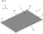
- the supporting frame 1 comprises several uprights 10 assembled together, delimiting a surface, called deployment surface S.
- the frame 1 is for example rectangular in shape.
- first upright 10a and a second upright 10b parallel to each other, defining two parallel guide sides (along X).
- a guide rail is made, designated respectively first guide rail 11a and second guide rail 11b.
- the installation also includes a series of blades 2 extending longitudinally (along Y), parallel to each other and mounted between the two guide rails 11a, 11b.
- the blades 2 are capable of moving, by translation in the two guide rails, in the deployment surface S delimited by the supporting frame 1, in a direction, called the deployment direction, parallel to that defined by the two guide rails (along the X axis).
- the number of blades 2 is of course adapted to the size of the installation, in particular that of the supporting frame.
- the blades 2 are both movable in translation in the deployment surface S, by being retractable or deployable, as well as adjustable in pivoting.
- the slats 2 When the slats 2 are deployed over the entire deployment surface S, they can take several orientations, for example a vertical orientation, allowing partial concealment, and a horizontal orientation, allowing total concealment, forming an occupant roof the entire deployment surface S.
- the installation is carried out so that all the blades are controlled with an identical orientation.
- a first operating state is defined in which the blades 2 are completely or partially retracted and a second operating state in which the blades 2 are fully deployed over the entire deployment surface.
- FIG. 1A shows the frame of the installation of the invention with the blades 2 rows and placed against each other, freeing an open area through the supporting frame 1.
- FIG. 1B shows the framework of the installation of the invention with the blades 2 fully deployed, open, oriented vertically.
- FIG. 1C shows the framework of the installation of the invention with the blades 2 fully deployed, closed, oriented horizontally, thus forming a roof.
- Each blade 2 has two ends, called the first end and the second end.
- a blade 2 carries a sliding shoe 20a, 20b cooperating on one side with the first guide rail 11a and on the other side with the second guide rail 11b.
- This pad is mounted to slide freely in its guide rail.
- the term "skate" is to be understood in a non-limiting manner and different equivalent solutions (pebbles for example) could be considered.
- each blade 2 can be defined by a rank i, with i ranging from 1 to N, with N greater than or equal to 2.
- the head blade is that of rank 1 and the tail blade is that of rank N.
- the blades advantageously all have an identical shape.
- the movement of the blades 2 in translation along the two guide rails 11a, 11b is ensured by a first drive system.
- This first drive system comprises at least one motor and a belt 31 driven by said motor, in a direction parallel to the direction of deployment, in one direction or the other.
- the motor and the belt 31 are for example inserted in the first upright 10a, carrying the first guide rail 11a.
- the direction of rotation of the motor defines the direction of movement of the blades 2 in translation in the deployment surface S.
- the first drive system also comprises a carriage 30 mounted on the belt 31 and on which is mounted a connecting member present at the first end of the head blade.
- the blades 2 are then connected together in single file so as to be driven, towed or pushed, by the head blade 2_1, itself driven by the carriage 30.
- each blade of rank i with i ranging from 2 to N-1 is connected to the blade of rank i-1 by a first connecting member 4_i and to the blade of rank i+1 by a second connecting member 4_i+ 1.
- the head blade, of row 1 is connected to the blade of row 2, using a single connecting member 4_1.
- the tail blade, of rank N is connected to the blade of rank N-1 by a connecting member 4_N-1 and to the supporting frame by a connecting member 4_N, advantageously of a shape distinct from that of the other connecting members ( Figure 2A ).
- Each articulated connecting member 4_i has a first end connected to an axis 21 of the blade of row i via a first pivot connection and a second end connected to an axis 21 of the blade of row i+1 via a second pivot connection.
- each connecting member advantageously comprises two links 40, 41 connected together by a central pivot connection 42, forming a V between them, the free ends of which are each mounted by a pivot connection on an attachment axis 21 present at the end of the blade to which they are attached.
- the axis 21 for mounting the link on the blade is for example aligned with its sliding shoe 20a, 20b, along the longitudinal axis of the blade.
- the connecting members 4 are advantageously present symmetrically on the two guide sides.
- the first drive system comprises means for limiting the movement of each connecting member when it is unfolded, so as to maintain a V shape between the two links (this is that is to say an angle between the two links 40, 41 of the connecting member which is distinct from a flat angle).
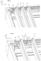
- these means can take the form of a stop mechanism 43 arranged between the two links of the connecting member ( 2D figure ).
- the connecting member 4_N attached to the tail blade, of rank N advantageously comprises a single link attached to the supporting frame, via a pivot-sliding type connection, this in order to gain compactness when storing the blades ( Figure 2A ).
- a first limit switch type sensor 50 is for example positioned to detect when this state is reached.
- the connecting members 4 When the head blade 2_1 is towed by the carriage 30, the connecting members 4 gradually unfold, one after the other until reaching the second operating state in which all the blades are fully deployed, being distributed over the entire the deployment surface S.
- a second limit switch type sensor (not shown) is for example positioned to detect when this state is reached.
- the pivoting of the blades 2 around their longitudinal axis is only permitted when the blades 2 are in the second operating state, that is to say when they are completely deployed.
- the installation includes a second drive system.
- the second drive system comprises several pivoting members 6, for example arranged on at least one guiding side of the blades 2.
- These pivoting members 6 are inserted in the first upright 10a, distributed along the first guide rail 11a. They are each fixed in translation in the first guide rail 11a and pivotable around an axis perpendicular to the direction of deployment (in the direction Y). They are distributed along the first guide rail 11a and spaced so as to each be aligned with the sliding shoe 20a of a separate blade 2 when the blades 2 are fully deployed. They each include a bearing 60 for receiving said sliding shoe 20a, aligned with the first guide rail when the blades 2 are deployed, and rotatable when it receives the sliding shoe 20a of the blade.
- the blades 2 can each be mounted freely to pivot around their sliding shoe 20b. However, the pivoting of the blade 2 will only be permitted when its sliding shoe 20a is aligned with its pivoting member 6 located on the first guide side.
- the actuation of the pivoting members 6 is carried out using a cylinder 70, for example electric, the rod of which is connected to a transmission bar 71.
- a cylinder 70 for example electric
- Each pivoting member 6 is connected to the transmission bar 71 via a link 61 , mounted at one end, via a pivot connection, on the transmission bar 71 and at its other end, via a fixed connection, on the pivoting member 6.
- the cylinder 70 is arranged to drive the transmission bar 71 in translation following a direction parallel to the direction of deployment (along the X axis) in one direction or the other.
- Each link 61 attached to the transmission bar 71 transforms the translation movement of the transmission bar 71 into a rotational movement of the pivot member 6 which is attached to it.
- the actuation of the transmission bar 71 causes the pivoting member 6 to rotate around its axis (in the direction Y of the blade), thus causing the blade to pivot around its axis.
- the blade is tilting.
- pivoting member 6 is entirely pivoted, its bearing 60 being vertical, placing the blade horizontally and in the closed state.
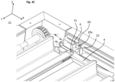
- a guide member 22 ( Figures 4A to 4C ) is positioned between its shoe 20a and its axis 21.
- This guide member 22 is configured to remain in support against the rail 11a, even during the rotation of the shoe 20a driven by the pivot member 6.
- This guide member 22 is free to slide in the rail, but remains fixed relative to the shoe 20a when the latter is pivoted by the pivoting member 6, allowing the blade to remain in its rail.
- each connecting member 4 arranged between two successive blades 2 is configured to be rigid in traction in the direction of deployment, when it is fully unfolded, so as to define a constant pitch of a blade to another, in the series of blades.
- Each connecting member 4 ensures that the sliding pad 20a of each blade 2 is positioned on the bearing 60 of the pivoting member 6 with which it is associated, once the deployment of the blades is completed.
- this degree of freedom is for example provided at the second guide side, between the sliding shoe 20b and the second guide rail 11b. This degree of freedom makes it possible to ensure the deployment or storage of the blades, even in the event of a lack of parallelism between the two guide rails 11a, 11b.
- the blades 2 advantageously have a shape making it possible to obtain a particularly compact assembly when they are all stored, placed against each other. For example, on a deployment surface of six meters in length, they can occupy 20% of this length when stowed.
- FIG 7B shows the configuration obtained when the blades are deployed and oriented horizontally. Their shape is designed to make the architecture compact.
- each upright of the supporting frame 1 can have a cover forming both its external covering and protecting its guide rail 11a, 11b from water and dust.
- the installation includes a control system configured to control the motor of the first drive system and the motor of the second drive system. In particular, it receives input instructions from a man-machine interface (remote control, smartphone, console, etc.).
- a man-machine interface remote control, smartphone, console, etc.
- the motors and the control system can be powered by one or more electrical power sources (battery, electrical network, photovoltaic panel, etc.).
- electrical power sources battery, electrical network, photovoltaic panel, etc.
- the invention has the advantage of decorrelating the translation movement of the blades 2 from the pivoting movement of the blades.
- the pivoting of the blades 2 is allowed when all the blades are deployed, their sliding shoe 20a cooperating with a pivoting member 6 positioned along the guide rail 11a.
- each pivoting member 6 is mounted on the first guide rail 11a, pivotable around an axis perpendicular to the direction of deployment. It does not move with blade 2 when deployed.
- the sliding of the blade 2 in the first guide rail 11a, via its sliding shoe 20a is carried out with a particularly low mechanical play, the sliding shoe being free in translation in the first guide rail along the axis with which he is associated.
Landscapes
- Engineering & Computer Science (AREA)
- Structural Engineering (AREA)
- Architecture (AREA)
- Civil Engineering (AREA)
- Blinds (AREA)
- Power-Operated Mechanisms For Wings (AREA)
- Refuge Islands, Traffic Blockers, Or Guard Fence (AREA)
Applications Claiming Priority (1)
| Application Number | Priority Date | Filing Date | Title |
|---|---|---|---|
| FR2207862A FR3138458B1 (fr) | 2022-07-29 | 2022-07-29 | Installation de protection contre le soleil ou les intempéries |
Publications (3)
| Publication Number | Publication Date |
|---|---|
| EP4321702A1 true EP4321702A1 (de) | 2024-02-14 |
| EP4321702B1 EP4321702B1 (de) | 2025-06-25 |
| EP4321702C0 EP4321702C0 (de) | 2025-06-25 |
Family
ID=83593840
Family Applications (1)
| Application Number | Title | Priority Date | Filing Date |
|---|---|---|---|
| EP23187097.3A Active EP4321702B1 (de) | 2022-07-29 | 2023-07-21 | Sonnen- oder wetterschutzanlage |
Country Status (3)
| Country | Link |
|---|---|
| EP (1) | EP4321702B1 (de) |
| ES (1) | ES3040988T3 (de) |
| FR (1) | FR3138458B1 (de) |
Citations (7)
| Publication number | Priority date | Publication date | Assignee | Title |
|---|---|---|---|---|
| EP2868833A1 (de) * | 2013-10-31 | 2015-05-06 | Soliso Europe | Lamellenpaneel für Leichtkonstruktion wie Pergola, Gartenlaube oder Ähnliches, und Leichtkonstruktion, die ein solches Paneel umfasst |
| EP2844817B1 (de) | 2012-05-04 | 2016-11-30 | Zurflüh-Feller | Schliess- oder sonnenschutzeinrichtung und verfahren zur realisierung eine der einrichtungen |
| EP3024997B1 (de) * | 2013-07-26 | 2017-11-29 | BRUSTOR, naamloze vennootschap | Sonnenblende |
| FR3069871A1 (fr) | 2017-08-04 | 2019-02-08 | Distral | Pergola ajustable |
| FR3093339A1 (fr) | 2019-02-28 | 2020-09-04 | Biossun | Installation pour couvrir une surface à l’aide de lames orientables translatées à plat |
| DE202021102781U1 (de) * | 2020-05-22 | 2021-10-27 | Gibus S.P.A. | Abdeckungsvorrichtung |
| EP3913162A1 (de) * | 2020-05-22 | 2021-11-24 | GIBUS S.p.A. | Abdeckungsvorrichtung |
Family Cites Families (1)
| Publication number | Priority date | Publication date | Assignee | Title |
|---|---|---|---|---|
| IL109652A (en) * | 1994-05-15 | 1997-06-10 | Yedidia Hagai | Louvered movable window shutter |
-
2022
- 2022-07-29 FR FR2207862A patent/FR3138458B1/fr active Active
-
2023
- 2023-07-21 ES ES23187097T patent/ES3040988T3/es active Active
- 2023-07-21 EP EP23187097.3A patent/EP4321702B1/de active Active
Patent Citations (7)
| Publication number | Priority date | Publication date | Assignee | Title |
|---|---|---|---|---|
| EP2844817B1 (de) | 2012-05-04 | 2016-11-30 | Zurflüh-Feller | Schliess- oder sonnenschutzeinrichtung und verfahren zur realisierung eine der einrichtungen |
| EP3024997B1 (de) * | 2013-07-26 | 2017-11-29 | BRUSTOR, naamloze vennootschap | Sonnenblende |
| EP2868833A1 (de) * | 2013-10-31 | 2015-05-06 | Soliso Europe | Lamellenpaneel für Leichtkonstruktion wie Pergola, Gartenlaube oder Ähnliches, und Leichtkonstruktion, die ein solches Paneel umfasst |
| FR3069871A1 (fr) | 2017-08-04 | 2019-02-08 | Distral | Pergola ajustable |
| FR3093339A1 (fr) | 2019-02-28 | 2020-09-04 | Biossun | Installation pour couvrir une surface à l’aide de lames orientables translatées à plat |
| DE202021102781U1 (de) * | 2020-05-22 | 2021-10-27 | Gibus S.P.A. | Abdeckungsvorrichtung |
| EP3913162A1 (de) * | 2020-05-22 | 2021-11-24 | GIBUS S.p.A. | Abdeckungsvorrichtung |
Also Published As
| Publication number | Publication date |
|---|---|
| FR3138458A1 (fr) | 2024-02-02 |
| EP4321702B1 (de) | 2025-06-25 |
| FR3138458B1 (fr) | 2024-06-28 |
| ES3040988T3 (en) | 2025-11-06 |
| EP4321702C0 (de) | 2025-06-25 |
Similar Documents
| Publication | Publication Date | Title |
|---|---|---|
| EP3443177B1 (de) | Vorrichtung zum abdecken und freilegen einer oberfläche mit gekoppelten selbstfahrenden einstellbaren lamellen | |
| EP2977323B1 (de) | Entfaltbare struktur mit federband | |
| EP3207190B1 (de) | Einheit zum abdecken und aufdecken einer oberfläche mit selbstangetriebenen verstellbaren lamellen | |
| EP3438371B1 (de) | Anpassbare pergola | |
| FR2977457A1 (fr) | Parasol comprenant des elements permettant de creer de l'ombre | |
| EP3176095B1 (de) | Ausklappbare struktur, die eine gesamtheit von solargeneratoren umfasst, ausklappsystem einer solchen ausklappbaren struktur und satellit, der ein solches system umfasst | |
| FR3028842A1 (fr) | Structure deployable escamotable a metre-ruban | |
| FR3075885A1 (fr) | Turboreacteur equipe d'un actionneur a double effet, pouvant etre utilise pour commander une inversion de poussee | |
| FR2508413A1 (fr) | Ensembles de feuilles deployables pour engin spatial | |
| EP4321702B1 (de) | Sonnen- oder wetterschutzanlage | |
| CA2931214A1 (fr) | Structure segmentee, en particulier pour reflecteur d'antenne de satellite, pourvue d'au moins un dispositif de deploiement a ruban | |
| EP2520494A1 (de) | Vorrichtung zum Schutz eines optischen Vielfachspiegelinstruments | |
| EP0330550B1 (de) | Niederhalter-System für entklappbare Elemente an Raumflugkörpern | |
| FR3044700A1 (fr) | Dispositif de fermeture | |
| FR2507655A1 (fr) | Installation de gradins escamotables | |
| EP0737599A1 (de) | In eine Bühne umwandelbarer Anhänger | |
| EP0953301A1 (de) | Schirm | |
| EP1619078B1 (de) | Rollo für Laderaumabdeckung für ein Kraftfahrzeug und hiermit ausgestattetes Fahrzeug | |
| EP0165113B1 (de) | Vorrichtung zum Decken und Abdecken eines Laderaums | |
| EP1568527A1 (de) | Verbesserte Sonnenblende für Kraftfahrzeug und Fahrzeugtür mit einer solchen Sonnenblende. | |
| EP0239454A1 (de) | Bewegungsmechanismus für ein Teil und seine Bestimmung für einen entfaltbaren Solarzellengenerator | |
| FR2655634A1 (fr) | Verin a lanterne a tiges creuses telescopiques et son utilisation. | |
| FR2982291A1 (fr) | Velum ou banne a vague permettant un controle de la tension de la toile | |
| EP0062569A1 (de) | Faltrolladen | |
| FR2968724A1 (fr) | Dispositif eolien repliable a axe vertical |
Legal Events
| Date | Code | Title | Description |
|---|---|---|---|
| PUAI | Public reference made under article 153(3) epc to a published international application that has entered the european phase |
Free format text: ORIGINAL CODE: 0009012 |
|
| STAA | Information on the status of an ep patent application or granted ep patent |
Free format text: STATUS: THE APPLICATION HAS BEEN PUBLISHED |
|
| AK | Designated contracting states |
Kind code of ref document: A1 Designated state(s): AL AT BE BG CH CY CZ DE DK EE ES FI FR GB GR HR HU IE IS IT LI LT LU LV MC ME MK MT NL NO PL PT RO RS SE SI SK SM TR |
|
| STAA | Information on the status of an ep patent application or granted ep patent |
Free format text: STATUS: REQUEST FOR EXAMINATION WAS MADE |
|
| 17P | Request for examination filed |
Effective date: 20240801 |
|
| RBV | Designated contracting states (corrected) |
Designated state(s): AL AT BE BG CH CY CZ DE DK EE ES FI FR GB GR HR HU IE IS IT LI LT LU LV MC ME MK MT NL NO PL PT RO RS SE SI SK SM TR |
|
| GRAP | Despatch of communication of intention to grant a patent |
Free format text: ORIGINAL CODE: EPIDOSNIGR1 |
|
| STAA | Information on the status of an ep patent application or granted ep patent |
Free format text: STATUS: GRANT OF PATENT IS INTENDED |
|
| INTG | Intention to grant announced |
Effective date: 20250205 |
|
| GRAS | Grant fee paid |
Free format text: ORIGINAL CODE: EPIDOSNIGR3 |
|
| GRAA | (expected) grant |
Free format text: ORIGINAL CODE: 0009210 |
|
| STAA | Information on the status of an ep patent application or granted ep patent |
Free format text: STATUS: THE PATENT HAS BEEN GRANTED |
|
| AK | Designated contracting states |
Kind code of ref document: B1 Designated state(s): AL AT BE BG CH CY CZ DE DK EE ES FI FR GB GR HR HU IE IS IT LI LT LU LV MC ME MK MT NL NO PL PT RO RS SE SI SK SM TR |
|
| REG | Reference to a national code |
Ref country code: GB Ref legal event code: FG4D Free format text: NOT ENGLISH |
|
| REG | Reference to a national code |
Ref country code: CH Ref legal event code: EP |
|
| REG | Reference to a national code |
Ref country code: CH Ref legal event code: EP |
|
| REG | Reference to a national code |
Ref country code: IE Ref legal event code: FG4D Free format text: LANGUAGE OF EP DOCUMENT: FRENCH |
|
| U01 | Request for unitary effect filed |
Effective date: 20250701 |
|
| U07 | Unitary effect registered |
Designated state(s): AT BE BG DE DK EE FI FR IT LT LU LV MT NL PT RO SE SI Effective date: 20250707 |
|
| U20 | Renewal fee for the european patent with unitary effect paid |
Year of fee payment: 3 Effective date: 20250722 |
|
| PGFP | Annual fee paid to national office [announced via postgrant information from national office to epo] |
Ref country code: ES Payment date: 20250801 Year of fee payment: 3 |
|
| PG25 | Lapsed in a contracting state [announced via postgrant information from national office to epo] |
Ref country code: NO Free format text: LAPSE BECAUSE OF FAILURE TO SUBMIT A TRANSLATION OF THE DESCRIPTION OR TO PAY THE FEE WITHIN THE PRESCRIBED TIME-LIMIT Effective date: 20250925 Ref country code: GR Free format text: LAPSE BECAUSE OF FAILURE TO SUBMIT A TRANSLATION OF THE DESCRIPTION OR TO PAY THE FEE WITHIN THE PRESCRIBED TIME-LIMIT Effective date: 20250926 |
|
| PGFP | Annual fee paid to national office [announced via postgrant information from national office to epo] |
Ref country code: MC Payment date: 20250722 Year of fee payment: 3 |
|
| PG25 | Lapsed in a contracting state [announced via postgrant information from national office to epo] |
Ref country code: HR Free format text: LAPSE BECAUSE OF FAILURE TO SUBMIT A TRANSLATION OF THE DESCRIPTION OR TO PAY THE FEE WITHIN THE PRESCRIBED TIME-LIMIT Effective date: 20250625 |
|
| PG25 | Lapsed in a contracting state [announced via postgrant information from national office to epo] |
Ref country code: RS Free format text: LAPSE BECAUSE OF FAILURE TO SUBMIT A TRANSLATION OF THE DESCRIPTION OR TO PAY THE FEE WITHIN THE PRESCRIBED TIME-LIMIT Effective date: 20250925 |
|
| PGFP | Annual fee paid to national office [announced via postgrant information from national office to epo] |
Ref country code: IE Payment date: 20250723 Year of fee payment: 3 |
|
| REG | Reference to a national code |
Ref country code: ES Ref legal event code: FG2A Ref document number: 3040988 Country of ref document: ES Kind code of ref document: T3 Effective date: 20251106 |
|
| PG25 | Lapsed in a contracting state [announced via postgrant information from national office to epo] |
Ref country code: IS Free format text: LAPSE BECAUSE OF FAILURE TO SUBMIT A TRANSLATION OF THE DESCRIPTION OR TO PAY THE FEE WITHIN THE PRESCRIBED TIME-LIMIT Effective date: 20251025 |
|
| PG25 | Lapsed in a contracting state [announced via postgrant information from national office to epo] |
Ref country code: SM Free format text: LAPSE BECAUSE OF FAILURE TO SUBMIT A TRANSLATION OF THE DESCRIPTION OR TO PAY THE FEE WITHIN THE PRESCRIBED TIME-LIMIT Effective date: 20250625 |
|
| PG25 | Lapsed in a contracting state [announced via postgrant information from national office to epo] |
Ref country code: CZ Free format text: LAPSE BECAUSE OF FAILURE TO SUBMIT A TRANSLATION OF THE DESCRIPTION OR TO PAY THE FEE WITHIN THE PRESCRIBED TIME-LIMIT Effective date: 20250625 |
|
| PG25 | Lapsed in a contracting state [announced via postgrant information from national office to epo] |
Ref country code: PL Free format text: LAPSE BECAUSE OF FAILURE TO SUBMIT A TRANSLATION OF THE DESCRIPTION OR TO PAY THE FEE WITHIN THE PRESCRIBED TIME-LIMIT Effective date: 20250625 |
|
| PG25 | Lapsed in a contracting state [announced via postgrant information from national office to epo] |
Ref country code: SK Free format text: LAPSE BECAUSE OF FAILURE TO SUBMIT A TRANSLATION OF THE DESCRIPTION OR TO PAY THE FEE WITHIN THE PRESCRIBED TIME-LIMIT Effective date: 20250625 |
|
| PLBE | No opposition filed within time limit |
Free format text: ORIGINAL CODE: 0009261 |
|
| STAA | Information on the status of an ep patent application or granted ep patent |
Free format text: STATUS: NO OPPOSITION FILED WITHIN TIME LIMIT |
|
| REG | Reference to a national code |
Ref country code: CH Ref legal event code: L10 Free format text: ST27 STATUS EVENT CODE: U-0-0-L10-L00 (AS PROVIDED BY THE NATIONAL OFFICE) Effective date: 20260507 |