EP4325105A1 - Soupape de commande - Google Patents
Soupape de commande Download PDFInfo
- Publication number
- EP4325105A1 EP4325105A1 EP22787629.9A EP22787629A EP4325105A1 EP 4325105 A1 EP4325105 A1 EP 4325105A1 EP 22787629 A EP22787629 A EP 22787629A EP 4325105 A1 EP4325105 A1 EP 4325105A1
- Authority
- EP
- European Patent Office
- Prior art keywords
- sealing
- wall part
- valve
- valve core
- side wall
- Prior art date
- Legal status (The legal status is an assumption and is not a legal conclusion. Google has not performed a legal analysis and makes no representation as to the accuracy of the status listed.)
- Pending
Links
Images




Classifications
-
- F—MECHANICAL ENGINEERING; LIGHTING; HEATING; WEAPONS; BLASTING
- F16—ENGINEERING ELEMENTS AND UNITS; GENERAL MEASURES FOR PRODUCING AND MAINTAINING EFFECTIVE FUNCTIONING OF MACHINES OR INSTALLATIONS; THERMAL INSULATION IN GENERAL
- F16K—VALVES; TAPS; COCKS; ACTUATING-FLOATS; DEVICES FOR VENTING OR AERATING
- F16K11/00—Multiple-way valves, e.g. mixing valves; Pipe fittings incorporating such valves
- F16K11/02—Multiple-way valves, e.g. mixing valves; Pipe fittings incorporating such valves with all movable sealing faces moving as one unit
- F16K11/08—Multiple-way valves, e.g. mixing valves; Pipe fittings incorporating such valves with all movable sealing faces moving as one unit comprising only taps or cocks
- F16K11/085—Multiple-way valves, e.g. mixing valves; Pipe fittings incorporating such valves with all movable sealing faces moving as one unit comprising only taps or cocks with cylindrical plug
-
- F—MECHANICAL ENGINEERING; LIGHTING; HEATING; WEAPONS; BLASTING
- F16—ENGINEERING ELEMENTS AND UNITS; GENERAL MEASURES FOR PRODUCING AND MAINTAINING EFFECTIVE FUNCTIONING OF MACHINES OR INSTALLATIONS; THERMAL INSULATION IN GENERAL
- F16K—VALVES; TAPS; COCKS; ACTUATING-FLOATS; DEVICES FOR VENTING OR AERATING
- F16K11/00—Multiple-way valves, e.g. mixing valves; Pipe fittings incorporating such valves
- F16K11/02—Multiple-way valves, e.g. mixing valves; Pipe fittings incorporating such valves with all movable sealing faces moving as one unit
- F16K11/08—Multiple-way valves, e.g. mixing valves; Pipe fittings incorporating such valves with all movable sealing faces moving as one unit comprising only taps or cocks
- F16K11/085—Multiple-way valves, e.g. mixing valves; Pipe fittings incorporating such valves with all movable sealing faces moving as one unit comprising only taps or cocks with cylindrical plug
- F16K11/0856—Multiple-way valves, e.g. mixing valves; Pipe fittings incorporating such valves with all movable sealing faces moving as one unit comprising only taps or cocks with cylindrical plug having all the connecting conduits situated in more than one plane perpendicular to the axis of the plug
-
- F—MECHANICAL ENGINEERING; LIGHTING; HEATING; WEAPONS; BLASTING
- F16—ENGINEERING ELEMENTS AND UNITS; GENERAL MEASURES FOR PRODUCING AND MAINTAINING EFFECTIVE FUNCTIONING OF MACHINES OR INSTALLATIONS; THERMAL INSULATION IN GENERAL
- F16K—VALVES; TAPS; COCKS; ACTUATING-FLOATS; DEVICES FOR VENTING OR AERATING
- F16K27/00—Construction of housing; Use of materials therefor
- F16K27/06—Construction of housing; Use of materials therefor of taps or cocks
- F16K27/065—Construction of housing; Use of materials therefor of taps or cocks with cylindrical plugs
-
- F—MECHANICAL ENGINEERING; LIGHTING; HEATING; WEAPONS; BLASTING
- F16—ENGINEERING ELEMENTS AND UNITS; GENERAL MEASURES FOR PRODUCING AND MAINTAINING EFFECTIVE FUNCTIONING OF MACHINES OR INSTALLATIONS; THERMAL INSULATION IN GENERAL
- F16K—VALVES; TAPS; COCKS; ACTUATING-FLOATS; DEVICES FOR VENTING OR AERATING
- F16K31/00—Actuating devices; Operating means; Releasing devices
- F16K31/02—Actuating devices; Operating means; Releasing devices electric; magnetic
- F16K31/04—Actuating devices; Operating means; Releasing devices electric; magnetic using a motor
- F16K31/041—Actuating devices; Operating means; Releasing devices electric; magnetic using a motor for rotating valves
-
- F—MECHANICAL ENGINEERING; LIGHTING; HEATING; WEAPONS; BLASTING
- F16—ENGINEERING ELEMENTS AND UNITS; GENERAL MEASURES FOR PRODUCING AND MAINTAINING EFFECTIVE FUNCTIONING OF MACHINES OR INSTALLATIONS; THERMAL INSULATION IN GENERAL
- F16K—VALVES; TAPS; COCKS; ACTUATING-FLOATS; DEVICES FOR VENTING OR AERATING
- F16K31/00—Actuating devices; Operating means; Releasing devices
- F16K31/44—Mechanical actuating means
- F16K31/53—Mechanical actuating means with toothed gearing
- F16K31/535—Mechanical actuating means with toothed gearing for rotating valves
-
- F—MECHANICAL ENGINEERING; LIGHTING; HEATING; WEAPONS; BLASTING
- F16—ENGINEERING ELEMENTS AND UNITS; GENERAL MEASURES FOR PRODUCING AND MAINTAINING EFFECTIVE FUNCTIONING OF MACHINES OR INSTALLATIONS; THERMAL INSULATION IN GENERAL
- F16K—VALVES; TAPS; COCKS; ACTUATING-FLOATS; DEVICES FOR VENTING OR AERATING
- F16K5/00—Plug valves; Taps or cocks comprising only cut-off apparatus having at least one of the sealing faces shaped as a more or less complete surface of a solid of revolution, the opening and closing movement being predominantly rotary
- F16K5/04—Plug valves; Taps or cocks comprising only cut-off apparatus having at least one of the sealing faces shaped as a more or less complete surface of a solid of revolution, the opening and closing movement being predominantly rotary with plugs having cylindrical surfaces; Packings therefor
- F16K5/0457—Packings
- F16K5/0471—Packings between housing and plug
Definitions
- the present application relates to the technical field of fluid control, and in particular to a control valve.
- Some systems are required to use a multi-way control valve to control flow paths.
- it is required to provide multiple flow passages in the control valve, and sealing members are required to seal the multiple flow passages.
- How to arrange the multiple flow passages and the sealing member to improve the stability of the control of the multiple flow paths and improve the sealing performance of the control valve is an urgent problem to be solved.
- the purpose of the present application is to provide a control valve that can improve the stability of fluid control of multiple flow paths and improve the sealing performance of the control valve.
- a control valve is provided according to the embodiments of the present application.
- the control valve includes a valve body, a valve core, and a sealing member.
- the valve body includes a side wall part, the control valve has a valve cavity, the side wall part is a peripheral wall of the valve cavity or at least part of the peripheral wall, and at least part of the valve core and the sealing member are arranged in the valve cavity,
- the control valve provided according to the embodiment of the present application includes the sealing member and the balance sealing block.
- a cross section of the sealing member is in an arc-shaped structure. Compared with an annular structure of a cross section of the sealing member, the sealing member according to the embodiments of the present application has a relatively large expansion space and a relatively low manufacturing precision.
- the balance sealing block is arranged between the side wall part and the valve core, and the balance sealing block and the sealing member are arranged along the circumferential direction of the valve core.
- the direction of the force or the component force applied to the valve core by the balance sealing block is opposite to the direction of the force or the component force applied to the valve core by the sealing member, so that the valve core can be conveniently kept coaxial with the side wall part, the rotation stability of the valve element is improved, fluid leakage caused by sealing deviation caused by eccentricity of the valve element is prevented, the sealing performance of the control valve is improved, and the stability of the control valve on fluid control is improved.
- a control valve 1 is provided according to an embodiment of the present application.
- the control valve 1 includes a valve body 10, a valve core 20, and a sealing member 41.
- the valve body 10 includes a side wall part 11, and the control valve 1 has a valve cavity 101.
- the side wall part 11 is a peripheral wall of the valve cavity 101 or at least part of the peripheral wall.
- At least part of the valve core 20 is arranged in the valve cavity 101, and the valve core 20 can be driven to rotate.
- the control valve 1 can further include a driving device 50 and a sealing ring 43, the driving device 50 includes a driving element, and the driving element may be an electric motor or a motor and a reduction gear set.
- the valve core 20 can be driven to rotate by the driving element in the driving device 50, and at least part of the sealing member 41 is arranged between the valve core 20 and the side wall part 11.
- the valve body 10 further includes a bottom wall part 12 and a top wall part 13, the bottom wall part 12, the top wall part 13, and the side wall part 11 enclose to form the valve cavity 101, and the sealing ring 43 is arranged between the top wall part 13 and the valve core 20.
- At least part of the side wall part 11 is located between the bottom wall part 12 and the top wall part 13.
- One of the bottom wall part 12 and the top wall part 13 is integrally formed with the side wall part 11, and the other of the bottom wall part 12 and the top wall part 13 is sealingly arranged with the side wall part 11.
- the top wall part 13 is integrally formed with the side wall part 11, and the bottom wall part 12 may be fixedly connected to the side wall part 11 and is sealingly arranged with the side wall part 11 by welding, so as to prevent fluid leakage.
- the sealing ring 43 is arranged between the top wall part 13 and the valve core 20.
- the valve core 20 is assembled along the direction from the bottom of the valve body 10 toward the top of the valve body 10, which can reduce the deformation of the sealing ring 43 and improve the sealing performance of the sealing ring 43.
- the control valve 1 includes at least five passages 30, the side wall part 11 has at least five communication ports, and the at least five communication ports are in communication with the valve cavity 101.
- each passage 30 penetrates through the side wall part 11 to form the communication port, and the other end of each passage 30 forms a valve port 102 of the control valve 1. Fluid can enter or exit the control valve 1 through the valve end port 102.
- the number of the passages 30 provided in the control valve 1 may be set according to requirements of a user, for example, the number may also be three, four, five, or six.
- the valve body 10 further includes a mounting part 14, the mounting part 14 is fixedly connected to the side wall part 11 and located on a side of the side wall part 11 away from the valve cavity 101.
- the mounting part 14 and the side wall part 11 may be integrally formed, the mounting part 14 has an mounting surface 141, and the valve port 102 of the control valve 1 penetrates through the mounting surface 141, so that all the valve ports 102 of the control valve 1 are provided in the mounting surface 141 and the orientations of all the valve ports 102 are same, which can relatively simplify assembly of the control valve 1 with other components, reduce leakage points of connecting portions, and improve the reliability of sealing.
- a cross section of the sealing member 41 along a direction perpendicular to a height direction of the sealing member 41 is in an arc-shaped structure.
- the sealing member 41 includes a sealing body 410, the sealing body 410 is arranged between the valve core 20 and the side wall part 11, an inner surface of the sealing body 410 is in contact with the valve core 20, and an outer surface of the sealing body 410 is in contact with the side wall part 11.
- the communication ports of the side wall part 11 in the area where the side wall part 11 is in contact with the sealing body 410 are defined as the first communication ports 311.
- the communication ports in the side wall part 11 includes the first communication ports 311, the valve ports 102 in communication with the first communication ports 311 are arranged in an array along the height direction of the side wall part 11 and the direction perpendicular to the height direction of the side wall part 11.
- a profile of the mounting surface 141 of the mounting part 14 is substantially in a rectangular structure, a length direction of the mounting surface 141 is parallel to the height direction of the side wall part 11, and the valve ports 102 in communication with the first communication ports 311 are arranged in an array along a length direction and a width direction of the mounting surface 141.
- the first communication ports 311 are arranged along the height direction of the side wall part 11 and a circumferential direction of the side wall part 11, and two columns of the first communication ports 311 are arranged along the circumferential direction of the side wall part 11.
- the side wall part 11 has eight first communication ports 311
- the side wall part 11 has four rows of the first communication ports 311 along the height direction of the side wall part 11
- each row of the first communication ports 311 has two first communication ports 311
- the control valve 1 has eight first valve ports 312 in one-to-one correspondence and in communication with the first communication ports 311.
- the sealing body 410 has through holes 411 penetrating through the sealing member 41.
- the number of the through holes 411 is the same with the number of the first communication ports 311 and the through holes 411 is in communication with the first communication ports 311 correspondingly.
- the through holes 411 are arranged along the height direction of the sealing member 41 and a circumferential direction of the sealing body 410, and the sealing body 410 is provided with two through holes 411 along the circumferential direction of the sealing body 410.
- the sealing body 410 has eight through holes 411, the sealing body 410 has four rows of the through holes 411 along the height direction of the sealing body 410, and each row of the through holes 411 has two through holes 411.
- the inner surface of the sealing body 410 is an arc surface, and the arc surface contacts the valve core 20.
- a central angle corresponding to the arc surface of the sealing body 410 is defined as ⁇ , and ⁇ is greater than a central angle formed by corresponding edges of the two communication ports of the side wall part 11 arranged along the circumferential direction of the side wall part 11.
- ⁇ is greater than or equal to 100 degrees and less than or equal to 180 degrees.
- ⁇ is greater than or equal to 100 degrees and less than or equal to 110 degrees.
- a maximum central angle formed by edges of the two first communication ports 311 arranged along the circumferential direction of the side wall part 11 with a circle center of the side wall part 11 is defined as ⁇ , and ⁇ is equal to 90 degrees.
- a maximum central angle formed by edges of the two through holes 411 of the sealing member 41 with a circle center of the arc surface of the sealing member 41 is 90 degrees.
- an angle of the rotation tolerance is defined as 0, and ⁇ +2 ⁇ .
- the angle of the rotation tolerance of the valve core 20 may be ⁇ 5 degrees, that is, when the driving element stops driving the valve core 20 to rotate, due to the influence of the control accuracy of the driving element or the signal transmission delay or the rotation inertia of the valve core 20, the valve core 20 may stop rotating at a position of 5 degrees before a set angle or continue to rotate by 5 degrees after the set angle, so that the valve core 20 has a rotation tolerance.
- the central angle ⁇ corresponding to the arc surface of the sealing body 410 is 100 degrees.
- the sealing member 41 further includes limiting parts 414 located at both ends of the sealing body 410 in the circumferential direction of the sealing body 410.
- the limiting part 414 has a limiting surface 4141, the limiting surface 4141 is joined between an inner surface and an outer surface of the sealing member 41.
- the valve body 10 further includes a blocking part 15, as shown in Figures 9 and 10 , the blocking part is a part of the side wall part 11.
- the blocking part 15 may be fixedly connected to the side wall part 11 and arranged in the valve cavity 101.
- the blocking part 15 has a blocking surface 151, the blocking surface 151 may extend along a radial direction of the side wall part 11 or extend at an angle relative to the radial direction of the side wall part 11.
- the blocking surface 151 is located in the valve cavity 101, and the limiting surface 4141 is in contact with the blocking surface 151. With the above configuration, the limiting surface 4141 and the blocking surface 151 are in cooperation with each other to prevent the rotation of the sealing member 41 and improve the sealing performance of the sealing member 41.
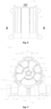
- the control valve 1 further includes a balance sealing block 42, and the balance sealing block 42 is arranged between the side wall part 11 and the valve core 20.
- the balance sealing block 42 and the sealing member 41 are respectively arranged on two sides of the valve core 20 in the radial direction of the valve core 20.
- a surface of the balance sealing block 42 facing the valve core 20 is an arc surface, an axis of the arc surface of the balance sealing block 42 coincides with an axis of the inner surface of the sealing body 410, and a radius of the arc surface of the balance sealing block 42 is equal to a radius of the inner surface of the sealing body 410.
- a height of the balance sealing block 42 may be equal to a height of the sealing member 41.
- a height of the sealing member 41 where the sealing member 41 contacts the valve core 10 and a height of the balance sealing block 42 where the balance sealing block 42 contacts the valve core 20 are equal.
- the balance sealing block 42 and the sealing member 41 can produce forces on the valve core 20 that are in a same magnitude and in opposite directions, the valve core 20 and the side wall part 11 can be kept to be arranged coaxially, the rotation stability of the valve core 20 can be improved, fluid leakage caused by the eccentricity of the valve core 20 can be prevented, the sealing performance of the control valve 1 can be improved, and the stability of the control valve 1 for fluid control can be improved.
- the sealing member 41 includes a first elastic pad 412 and a first sealing element 413 that are fixedly connected with each other.
- the first elastic pad 412 is arranged between the first sealing element 413 and the side wall part 11, and the first sealing element 413 is arranged between the first elastic pad 412 and the valve core 20 and is in contact with the valve core 20.
- the main material of the first sealing element 413 may be Teflon, for example, the first sealing element 413 may be processed and formed of Teflon, the first elastic pad 412 may be processed and formed of rubber, and the first elastic pad 412 and the first sealing element 413 are fixed by bonding to form an integrated structure. In that case, a roughness of a surface of the first sealing element 412 facing the valve core 20 is less than a roughness of a surface of the first elastic pad 412 away from the valve core 20.
- the main material of the first sealing element 412 is Teflon, so that the first sealing element 412 can perform function not only of sealing, but also of lubrication, which can reduce a friction force between the valve core 20 and the sealing member 41, thereby relatively reducing the driving force of the control valve 1.
- the first elastic pad 421 includes a main body part and a protrusion part, and the protrusion part is in contact with the side wall part 11.
- the protrusion part may include a plurality of axial protrusions and a plurality of circumferential protrusions that are intersected with each other.
- the axial protrusion extends along a height direction of the first elastic pad 421, and the circumferential protrusion extends along a circumferential direction of the first elastic pad 421.
- the balance sealing block 42 may include a second elastic pad 423 and a second sealing element 424 that are fixedly connected.
- the second elastic pad 423 is arranged between the second sealing element 424 and the side wall part 11, the second sealing element 424 is arranged between the second elastic pad 423 and the valve core 20 and is in contact with the valve core 20.
- the main material of the second sealing element 424 may be Teflon, for example, the second sealing element 424 may be processed and formed of Teflon, the second elastic pad 423 may be processed and formed of rubber, and the second elastic pad 423 and the second sealing element 424 are fixed by bonding to form an integrated structure.
- a roughness of a surface of the second sealing element 424 facing the valve core 20 is less than that a roughness of a surface of the second elastic pad 423 away from the valve core 20.
- the main material of the second sealing element 424 is Teflon, so that the second sealing element 424 can perform function not only of sealing, but also of lubrication, which can reduce the friction force between the valve core 20 and the sealing member 41, thereby relatively reducing the driving force of the control valve 1.
- the valve body 10 has an accommodation cavity 152 and an opening 153 along the radial direction of the side wall part 11, and the accommodation cavity 152 is in communication with the valve cavity 101 through the opening 153.
- An area of a cross section of the accommodation cavity 152 is greater than an area of a cross section of the opening 153.
- the balance sealing block 42 includes a first portion 421 and a second portion 422 that are fixedly connected to each other, an area of a cross section of the first portion 421 is greater than an area of a cross section of the second portion 422, the first portion 421 is arranged in the accommodation cavity 152, and the second portion 422 is arranged between the valve core 20 and the first portion 421. In that case, the second portion 422 penetrates through the opening 153 to contact the valve core 20.
- the cross section is a cross section obtained by cutting the control valve 1 along a direction perpendicular to a height direction of the balance sealing block 42 or along the direction perpendicular to the height direction of the side wall part 11.
- the balance sealing block 42 can be limited in the accommodation cavity 152, facilitating the mounting of the balance sealing block 42.
- the first portion 421 may be the second elastic pad 423
- the second portion 422 may be the second sealing element 424
- the first portion 421 may be a structure formed by the second elastic pad 423 and a part of the second sealing element 424
- the second portion 422 may be a structure formed by the rest part of the second sealing element 424.
- the communication ports of the side wall part 11 further includes a second communication port 321, and the second communication port 321 is located at an end of the side wall part 11 in the height direction of the side wall part 11 and is provided away from the sealing member 41.
- the valve core 20 is in a columnar structure, and the valve core 20 includes a top plate 201, a bottom plate 202, an internal communication cavity 21, a plurality of external communication cavities 22, a first partition 23 and a second partition 24.
- the plurality of external communication cavities 22, the first partition 23, and the second partition 24 are located between the top plate 201 and the bottom plate 202, the internal communication cavity 21 is located between the top plate 201 and the bottom plate 202 and penetrates through the bottom plate 202.
- At least part of the external communication cavities 22 are arranged on an outer peripheral side of the internal communication cavity 21, the first partition 23 is located between the internal communication cavity 21 and the external communication cavity 22, and the second partition 24 is located between two adjacent external communication cavities 22.
- the first partition 23 has a hole passage 231, and the internal communication cavity 21 is in communication with a part of the external communication cavities 22 through the hole passage 231.
- the second communication port 321 is in communication with the internal communication cavity 21 through the valve cavity 101
- the first communication ports 311 are in communication with the external communication cavities 22 through the through holes 411 of the sealing body 410.
- Each of the external communication cavities 22 is formed into an independent space by the second partition 24.
- the valve core 20 is rotated so as to be able to communicate or shut off two valve ports corresponding to the external communication cavity 22 through the external communication cavity 22, and/or, the valve core 20 is rotated so as to be able to communicate or shut off the corresponding two valve ports through the internal communication cavity 21, the hole passage 231, and the external communication cavity 22.
- One of the two valve ports corresponds to the internal communication cavity 21 and the other of the two valve ports corresponds to the external communication cavity 22.
- the top wall part 13 and the side wall part 11 of the valve body 10 are formed as an integrated structure by injection molding.
- the valve body 10 further includes a protrusion portion 16, and the protrusion portion 16 protrudes from the top wall part 13 and is arranged in the valve cavity.
- the protrusion portion 16 has a first limit groove 16a, and a groove opening of the first limit groove 16a is in communication with the valve cavity.
- a part of the inner surface of the side wall part 11 can form a groove wall of the first limit groove 16a, one end of the sealing member 41 in the height direction is arranged in the first limit groove 16a, thereby limiting the assembly position of the sealing member 41.
- a width of the first limit groove 16a may be greater than or equal to a thickness of the sealing member 41 in the radial direction of the sealing member 41.
- multiple connecting ribs may be provided on the top wall part 13, and the connecting ribs are arranged along the radial direction of the top wall part 13.
- a group of connecting ribs extending along the circumferential direction of the top wall part 13 may be provided on the top wall part 13, so as to increase the structural strength of the top wall part 13.
- the protrusion portion 16 may further include a second limit groove, a groove opening of the second limit groove is in communication with the valve cavity, one end of the balance sealing block 42 in the height direction is arranged in the second limit groove, and a width of the second limit groove may be greater than or equal to a thickness of the balance sealing block 42 in the radial direction.
- the communication ports further include a second communication port 321 and the valve body includes a mounting part 14, the second communication port 321 is located at one end of the side wall part 11 in the height direction and is located on a side of the side wall part 11 away from the sealing member 41.
- the mounting part 14 has a mounting surface 141.
- the valve ports 102 in communication with the first communication ports 311 and the valve port 102 in communication with the second communication port 321 are rectangular, and cross-sectional areas thereof are the same. With the above configuration, the rate of fluid flow passing through the valve ports 102 can tend to be equal.
- the valve ports 102 in communication with the first communication ports 311 are defined as first valve ports 312, and the valve port 102 in communication with the second communication port 321 is defined as a second valve port 322.
- a length of the second valve port 322 is greater than twice of a length of the first valve port 312.
- the mounting part 14 of the valve body 10 may further include a reinforcing rib 142, the reinforcing rib 142 extends along a width direction of the second valve port 322 and is connected between two surfaces of the second valve port 322 oppositely arranged along a height direction of the control valve.
- the control valve 1 includes the sealing member 41 and the balance sealing block 42.
- the cross section of the sealing member 41 is in an arc-shaped structure. Compared with an annular structure of a cross section of the sealing member, the sealing member 41 according to the embodiments of the present application has a relatively large expansion space and a relatively low manufacturing precision.
- the balance sealing block 42 is arranged between the side wall part 11 and the valve core 20, and the balance sealing block 42 and the sealing member 41 are respectively arranged on both sides of the valve core 20 in the radial direction of the valve core 20.
- the surface of the balance sealing block 42 facing the valve core 20 is an arc surface, the circle center of the arc surface of the balance sealing block 42 coincides with the circle center of the inner surface of the sealing body 410, and the radius of the arc surface of the balance sealing block 42 is equal to the radius of the inner surface of the sealing body 410.
- the balance sealing block 42 and the sealing member 41 can apply force on the valve core 20 that are equal and in opposite directions, so that the valve core 20 and the side wall part 11 can be maintained coaxial, the rotation stability of the valve core 20 can be improved, fluid leakage caused by the eccentricity of the valve core 20 can be prevented, the sealing performance of the control valve 1 can be improved, and the stability of the control valve 1 for fluid control can be improved, so as to facilitate popularization and application.
Landscapes
- Engineering & Computer Science (AREA)
- General Engineering & Computer Science (AREA)
- Mechanical Engineering (AREA)
- Sliding Valves (AREA)
- Multiple-Way Valves (AREA)
- Valve Housings (AREA)
Applications Claiming Priority (2)
| Application Number | Priority Date | Filing Date | Title |
|---|---|---|---|
| CN202110411378.0A CN115218001B (zh) | 2021-04-16 | 2021-04-16 | 控制阀 |
| PCT/CN2022/087035 WO2022218407A1 (fr) | 2021-04-16 | 2022-04-15 | Soupape de commande |
Publications (2)
| Publication Number | Publication Date |
|---|---|
| EP4325105A1 true EP4325105A1 (fr) | 2024-02-21 |
| EP4325105A4 EP4325105A4 (fr) | 2025-04-09 |
Family
ID=83604542
Family Applications (1)
| Application Number | Title | Priority Date | Filing Date |
|---|---|---|---|
| EP22787629.9A Pending EP4325105A4 (fr) | 2021-04-16 | 2022-04-15 | Soupape de commande |
Country Status (5)
| Country | Link |
|---|---|
| US (1) | US12297917B2 (fr) |
| EP (1) | EP4325105A4 (fr) |
| JP (1) | JP7644261B2 (fr) |
| CN (1) | CN115218001B (fr) |
| WO (1) | WO2022218407A1 (fr) |
Families Citing this family (6)
| Publication number | Priority date | Publication date | Assignee | Title |
|---|---|---|---|---|
| WO2022151757A1 (fr) * | 2021-01-18 | 2022-07-21 | 杭州奥科美瑞科技有限公司 | Dispositif de vanne |
| CN116160915A (zh) * | 2022-12-15 | 2023-05-26 | 华为数字能源技术有限公司 | 一种温控系统、车辆、储能系统及多通阀 |
| WO2024135386A1 (fr) * | 2022-12-20 | 2024-06-27 | 株式会社アイシン | Matériau d'étanchéité pour pompe rotative |
| CN116123315A (zh) * | 2023-02-16 | 2023-05-16 | 武汉显捷电子有限公司 | 一种七通道水阀调节机构 |
| CN116642034B (zh) * | 2023-05-16 | 2026-01-27 | 安徽美芝精密制造有限公司 | 阀芯、多通阀、热管理系统和车辆 |
| CN121739123A (zh) * | 2024-09-26 | 2026-03-27 | 浙江三花汽车零部件有限公司 | 阀装置及密封件 |
Family Cites Families (18)
| Publication number | Priority date | Publication date | Assignee | Title |
|---|---|---|---|---|
| FR2844571B1 (fr) | 2002-09-18 | 2008-02-29 | Valeo Thermique Moteur Sa | Vanne de commande pour un circuit de fluide et circuit comportant cette vanne |
| WO2007136869A2 (fr) * | 2006-05-17 | 2007-11-29 | Purdue Research Foundation | Vanne de régulation à action rapide |
| JP5677775B2 (ja) | 2010-07-15 | 2015-02-25 | 株式会社不二工機 | バタフライバルブ |
| US9127694B2 (en) * | 2011-09-09 | 2015-09-08 | Woodward, Inc. | High-flow electro-hydraulic actuator |
| CN103791114A (zh) * | 2014-01-17 | 2014-05-14 | 葛京鹏 | 一种柱筒阀结构 |
| JP6351352B2 (ja) | 2014-04-30 | 2018-07-04 | 株式会社不二工機 | 流路切換弁 |
| JP6656846B2 (ja) | 2015-08-26 | 2020-03-04 | 株式会社不二工機 | 流路切換弁及びシール部材 |
| JP6775466B2 (ja) * | 2017-04-27 | 2020-10-28 | 日立オートモティブシステムズ株式会社 | 流量制御弁 |
| US10883619B2 (en) * | 2017-06-27 | 2021-01-05 | Hayward Industries, Inc. | Multi-position valve |
| JP7221883B2 (ja) * | 2017-06-30 | 2023-02-14 | ジャージャン サンフア オートモーティヴ コンポーネンツ カンパニー リミテッド | 電動弁 |
| CN107830207B (zh) | 2017-10-31 | 2019-04-26 | 东宁晟(北京)数字科技有限公司 | 一种冷热混水旋塞阀 |
| CN209278546U (zh) * | 2018-11-21 | 2019-08-20 | 天津市恒科伟业科技有限公司 | 一种气动转向阀 |
| CN112081978B (zh) * | 2019-06-14 | 2022-10-18 | 浙江三花商用制冷有限公司 | 一种控制阀 |
| CN112240404A (zh) * | 2019-07-18 | 2021-01-19 | 浙江三花汽车零部件有限公司 | 一种控制阀 |
| CN110440032B (zh) * | 2019-09-10 | 2024-04-12 | 大连海事大学 | 一种多工位气动换向阀 |
| CN112032326B (zh) * | 2020-08-21 | 2021-05-18 | 浙江大学 | 分块式活塞阀芯结构及其组件、阀门和方法 |
| CN215928493U (zh) | 2021-06-24 | 2022-03-01 | 盾安汽车热管理科技有限公司 | 控制阀 |
| CN215487806U (zh) * | 2021-08-17 | 2022-01-11 | 艾默林汽车活动组件(无锡)有限公司 | 一种多通阀 |
-
2021
- 2021-04-16 CN CN202110411378.0A patent/CN115218001B/zh active Active
-
2022
- 2022-04-15 WO PCT/CN2022/087035 patent/WO2022218407A1/fr not_active Ceased
- 2022-04-15 JP JP2023563125A patent/JP7644261B2/ja active Active
- 2022-04-15 US US18/555,532 patent/US12297917B2/en active Active
- 2022-04-15 EP EP22787629.9A patent/EP4325105A4/fr active Pending
Also Published As
| Publication number | Publication date |
|---|---|
| US20240191805A1 (en) | 2024-06-13 |
| EP4325105A4 (fr) | 2025-04-09 |
| CN115218001A (zh) | 2022-10-21 |
| JP7644261B2 (ja) | 2025-03-11 |
| US12297917B2 (en) | 2025-05-13 |
| JP2024514650A (ja) | 2024-04-02 |
| WO2022218407A1 (fr) | 2022-10-20 |
| CN115218001B (zh) | 2025-11-11 |
Similar Documents
| Publication | Publication Date | Title |
|---|---|---|
| EP4325105A1 (fr) | Soupape de commande | |
| US12313169B2 (en) | Control valve and sealing component | |
| US12345341B2 (en) | Control valve | |
| US20230332696A1 (en) | Control valve | |
| WO2023071942A1 (fr) | Soupape multivoie | |
| EP4397894A1 (fr) | Ensemble de contrôle de fluide et dispositif de contrôle de fluide | |
| CN116292980A (zh) | 一种可进行比例调节的多通阀 | |
| EP4325101A1 (fr) | Vanne de commande | |
| CN115654177B (zh) | 一种多通阀 | |
| US20240288080A1 (en) | Control valve | |
| EP4273422A1 (fr) | Joint d'étanchéité, ensemble fluide le comprenant, et dispositif à fluide | |
| CN222799337U (zh) | 电子膨胀阀 | |
| CN117869626A (zh) | 多通阀 | |
| CN221974370U (zh) | 一种阀装置 | |
| CN223191053U (zh) | 一种阀装置 | |
| CN221003881U (zh) | 多通阀 | |
| CN114811110A (zh) | 电动阀 | |
| EP4403806A1 (fr) | Ensemble de commande de fluide | |
| JP3217937U (ja) | ボールねじ | |
| WO2025256398A1 (fr) | Détendeur électronique, système de réfrigération et véhicule | |
| CN120557393A (zh) | 一种阀 | |
| CN118049498A (zh) | 多端口阀门安装结构和汽车热管理系统 | |
| CN119222350A (zh) | 一种阀装置和集成组件 |
Legal Events
| Date | Code | Title | Description |
|---|---|---|---|
| STAA | Information on the status of an ep patent application or granted ep patent |
Free format text: STATUS: THE INTERNATIONAL PUBLICATION HAS BEEN MADE |
|
| PUAI | Public reference made under article 153(3) epc to a published international application that has entered the european phase |
Free format text: ORIGINAL CODE: 0009012 |
|
| STAA | Information on the status of an ep patent application or granted ep patent |
Free format text: STATUS: REQUEST FOR EXAMINATION WAS MADE |
|
| 17P | Request for examination filed |
Effective date: 20231027 |
|
| AK | Designated contracting states |
Kind code of ref document: A1 Designated state(s): AL AT BE BG CH CY CZ DE DK EE ES FI FR GB GR HR HU IE IS IT LI LT LU LV MC MK MT NL NO PL PT RO RS SE SI SK SM TR |
|
| DAV | Request for validation of the european patent (deleted) | ||
| DAX | Request for extension of the european patent (deleted) | ||
| A4 | Supplementary search report drawn up and despatched |
Effective date: 20250307 |
|
| RIC1 | Information provided on ipc code assigned before grant |
Ipc: F16K 31/04 20060101ALI20250303BHEP Ipc: F16K 31/53 20060101ALI20250303BHEP Ipc: F16K 5/04 20060101ALI20250303BHEP Ipc: F16K 11/085 20060101ALI20250303BHEP Ipc: F16K 27/06 20060101AFI20250303BHEP |
|
| STAA | Information on the status of an ep patent application or granted ep patent |
Free format text: STATUS: EXAMINATION IS IN PROGRESS |
|
| 17Q | First examination report despatched |
Effective date: 20260107 |