EP4397894A1 - Ensemble de contrôle de fluide et dispositif de contrôle de fluide - Google Patents
Ensemble de contrôle de fluide et dispositif de contrôle de fluide Download PDFInfo
- Publication number
- EP4397894A1 EP4397894A1 EP22863420.0A EP22863420A EP4397894A1 EP 4397894 A1 EP4397894 A1 EP 4397894A1 EP 22863420 A EP22863420 A EP 22863420A EP 4397894 A1 EP4397894 A1 EP 4397894A1
- Authority
- EP
- European Patent Office
- Prior art keywords
- port
- communication
- chamber
- pore
- fluid control
- Prior art date
- Legal status (The legal status is an assumption and is not a legal conclusion. Google has not performed a legal analysis and makes no representation as to the accuracy of the status listed.)
- Pending
Links
Images


Classifications
-
- F—MECHANICAL ENGINEERING; LIGHTING; HEATING; WEAPONS; BLASTING
- F16—ENGINEERING ELEMENTS AND UNITS; GENERAL MEASURES FOR PRODUCING AND MAINTAINING EFFECTIVE FUNCTIONING OF MACHINES OR INSTALLATIONS; THERMAL INSULATION IN GENERAL
- F16K—VALVES; TAPS; COCKS; ACTUATING-FLOATS; DEVICES FOR VENTING OR AERATING
- F16K11/00—Multiple-way valves, e.g. mixing valves; Pipe fittings incorporating such valves
- F16K11/02—Multiple-way valves, e.g. mixing valves; Pipe fittings incorporating such valves with all movable sealing faces moving as one unit
- F16K11/08—Multiple-way valves, e.g. mixing valves; Pipe fittings incorporating such valves with all movable sealing faces moving as one unit comprising only taps or cocks
- F16K11/085—Multiple-way valves, e.g. mixing valves; Pipe fittings incorporating such valves with all movable sealing faces moving as one unit comprising only taps or cocks with cylindrical plug
- F16K11/0856—Multiple-way valves, e.g. mixing valves; Pipe fittings incorporating such valves with all movable sealing faces moving as one unit comprising only taps or cocks with cylindrical plug having all the connecting conduits situated in more than one plane perpendicular to the axis of the plug
-
- F—MECHANICAL ENGINEERING; LIGHTING; HEATING; WEAPONS; BLASTING
- F16—ENGINEERING ELEMENTS AND UNITS; GENERAL MEASURES FOR PRODUCING AND MAINTAINING EFFECTIVE FUNCTIONING OF MACHINES OR INSTALLATIONS; THERMAL INSULATION IN GENERAL
- F16K—VALVES; TAPS; COCKS; ACTUATING-FLOATS; DEVICES FOR VENTING OR AERATING
- F16K5/00—Plug valves; Taps or cocks comprising only cut-off apparatus having at least one of the sealing faces shaped as a more or less complete surface of a solid of revolution, the opening and closing movement being predominantly rotary
- F16K5/04—Plug valves; Taps or cocks comprising only cut-off apparatus having at least one of the sealing faces shaped as a more or less complete surface of a solid of revolution, the opening and closing movement being predominantly rotary with plugs having cylindrical surfaces; Packings therefor
- F16K5/0457—Packings
- F16K5/0471—Packings between housing and plug
Definitions
- the present application relates to the fluid control technology and in particular to a fluid control assembly and fluid control device.
- a thermal management system requires a fluid control assembly to realize fluid control of multiple flow paths.
- the fluid control assembly comprises a connecting member, a valve core and a seal.
- the seal comprises a pore passage connected to a communication hole located on the connecting member.
- the seal is located between the connecting member and the valve core. How to design the fluid control assembly to improve a sealing performance of the fluid control assembly is an urgent problem that needs to be solved.
- the purpose of the present application is to provide a fluid control assembly and a fluid control device, which are beneficial for improving a sealing performance of the fluid control assembly.
- an embodiment of the present application provides a fluid control assembly with an accommodation chamber and a communication port.
- the fluid control assembly comprises a connecting member, a valve core, and a seal.
- the connecting member comprises a side wall portion, which forms at least part of a peripheral wall of the accommodation chamber, the communication port is located in the side wall portion, and at least part of the valve core is located in the accommodation chamber.
- At least part of the seal in a radial direction of the accommodation chamber is located between the side wall portion and the valve core, the seal comprises pore passages corresponding to the communication port; where the orthographic projections of all the pore passages in the seal in an axial direction of the seal are arranged at intervals in a circumferential direction of the valve core.
- the pore passages comprise a first pore passage and a second pore passage. The first pore passage and the second pore passage are spaced apart in the axial direction of the seal.
- an embodiment of the present application provides a fluid control device, comprising a fluid management assembly and at least one fluid control assembly according to any one of the above embodiments, the fluid control assembly has a flow passage, and a port of the fluid management assembly is in communication with the flow passage.
- the fluid control assembly and the fluid control device comprise a connecting member, a valve core and a seal. At least part of the seal is sandwiched between the side wall portion of the connecting member and the valve core.
- the seal comprises pore passages in communication with the communication ports of the fluid control assembly, which enable fluid to flow to the communication ports through the pore passages.
- the orthographic projections of the pore passages of the seal in the axial direction of the seal are arranged at intervals in the circumferential direction of the valve core.
- the pore passages comprise the first pore passage and the second pore passage. The first pore passage and the second pore passage are spaced apart in the axial direction of the seal.
- An embodiment of the present application provides a fluid control assembly that can be applied to a vehicle thermal management system, specifically a coolant circulation system, and can perform flow path conduction and switching functions for the thermal management system.
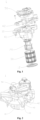
- a fluid control assembly 1 comprises a connecting member 10, a valve core 20 and a seal 30.
- the fluid control assembly 1 has an accommodation chamber 101 and a communication port 102.
- the communication port 102 is adjacent to the accommodation chamber 101 and is in communication with the accommodation chamber 101.
- the connecting member 10 comprises a side wall portion 11, which forms at least part of a peripheral wall of the accommodation chamber 101, and the communication port 102 is located in the side wall portion 11.
- the connecting member 10 can further comprise a top wall portion and a bottom cover 12, and the side wall portion 11, the top wall portion and the bottom cover 12 define the accommodation chamber 101. At least part of the side wall portion 11 is located between the top wall portion and the bottom cover 12.
- the fluid control assembly 1 further comprises a driving assembly 50.
- the driving assembly 50 comprises a driving member.
- the driving member can comprise a motor or a combination of a motor and a transmission gear set.
- the driving member is connected to the valve core 20 in transmission way, so that the driving member drives the valve core 20 to rotate.
- the first pore passages 32 and the second pore passages 33 arranged at intervals in the circumferential direction of the valve core 20 are located at different levels of the seal 30, respectively.
- the seal 30 of the flow control device provided by the embodiment of the present application, it is beneficial for increasing a length of a wall portion between the two pore passages 31 located at the same level, so that the valve core 20 can tightly press a wall portion of the seal 30 when rotating, thus improving the sealing performance of the fluid control assembly.
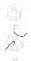
- the first seal 30 comprises a first fitting part 34, as shown in Figure 11
- the connecting member 10 comprises a limiting part 14, as shown in Figure 6
- the first fitting part 34 is limitedly connected to the limiting part 14.
- the first fitting part 34 can be one of a hole structure and a protruding structure
- the limiting part 14 can be the other one of a hole structure and a protruding structure, where the protruding structure is inserted into the hole structure for position limiting.
- the first seal 30 comprises a first circumferential wall portion 35 and a second circumferential wall portion 36.
- the first circumferential wall portion 35 and an orthogonal projection of the second circumferential wall portion 36 in the axial direction of the first seal 30 are arranged in the circumferential direction of the valve core 20.
- the first circumferential wall portion 35 is located between a first sub-pore passage 321 and a third sub-pore passage 323, and the first circumferential wall portion 35 and the second sub-pore passage 322 are respectively provided on two sides of the first seal 30 in a radial direction.
- a central angle a1 corresponding to the first circumferential wall portion 35 is greater than 90 degrees and less than 180 degrees.
- the second circumferential wall portion 36 is located between a fourth sub-pore passage 331 and the fifth sub-pore passage 332.
- a central angle a2 corresponding to the second circumferential wall portion 36 is greater than 180 degrees.
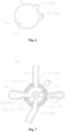
- the fluid control assembly is in a third operating mode.
- the valve core 20 is located at a third position, where the third port P3 is in communication with the fifth port P5 through the third sub-pore passage 323, the first chamber CA1, the second through hole 2312, the fourth chamber CA4 and the fifth sub-pore passage 332, and the fourth port P4 is in a closed state.
- the first port P1 is in communication with the second port P2 through the first sub-pore passage 321, the second chamber CA2 and the second sub-pore passage 322.
- the first pore passages 32 and the second pore passages 32 arranged at intervals in the circumferential direction of the valve core 20 are respectively located at different levels of the seal 30.
- the seal 30 of the flow control device provided by the embodiment of the present application can easily increase a length of the wall portion between the two pore passages at the same level position, so that the valve core 20 can tightly press the wall portion of the seal 30 when rotating, which can improve the sealing performance of fluid control assembly 1, facilitating promotion and application.
Landscapes
- Engineering & Computer Science (AREA)
- General Engineering & Computer Science (AREA)
- Mechanical Engineering (AREA)
- Multiple-Way Valves (AREA)
- Valve Housings (AREA)
- Sliding Valves (AREA)
Applications Claiming Priority (2)
| Application Number | Priority Date | Filing Date | Title |
|---|---|---|---|
| CN202111005738.3A CN115727167A (zh) | 2021-08-30 | 2021-08-30 | 流体控制组件和流体控制装置 |
| PCT/CN2022/115675 WO2023030285A1 (fr) | 2021-08-30 | 2022-08-30 | Ensemble de contrôle de fluide et dispositif de contrôle de fluide |
Publications (2)
| Publication Number | Publication Date |
|---|---|
| EP4397894A1 true EP4397894A1 (fr) | 2024-07-10 |
| EP4397894A4 EP4397894A4 (fr) | 2025-08-13 |
Family
ID=85290891
Family Applications (1)
| Application Number | Title | Priority Date | Filing Date |
|---|---|---|---|
| EP22863420.0A Pending EP4397894A4 (fr) | 2021-08-30 | 2022-08-30 | Ensemble de contrôle de fluide et dispositif de contrôle de fluide |
Country Status (5)
| Country | Link |
|---|---|
| US (1) | US20240353012A1 (fr) |
| EP (1) | EP4397894A4 (fr) |
| JP (1) | JP7724366B2 (fr) |
| CN (1) | CN115727167A (fr) |
| WO (1) | WO2023030285A1 (fr) |
Families Citing this family (7)
| Publication number | Priority date | Publication date | Assignee | Title |
|---|---|---|---|---|
| CN115727166A (zh) * | 2021-08-30 | 2023-03-03 | 浙江三花汽车零部件有限公司 | 流体控制组件和流体控制装置 |
| WO2024199331A1 (fr) * | 2023-03-31 | 2024-10-03 | 浙江三花汽车零部件有限公司 | Soupape de commande |
| CN116278624B (zh) * | 2023-04-25 | 2025-12-26 | 重庆超力高科技股份有限公司 | 具有多通阀功能的集成热管理模块 |
| WO2025002215A1 (fr) * | 2023-06-29 | 2025-01-02 | 浙江三花汽车零部件有限公司 | Ensemble soupape de commande et dispositif de commande de fluide |
| CN119222359A (zh) * | 2023-06-29 | 2024-12-31 | 浙江三花汽车零部件有限公司 | 流体控制装置 |
| CN119572752A (zh) * | 2023-09-07 | 2025-03-07 | 浙江三花汽车零部件有限公司 | 一种流体控制组件及热管理系统 |
| WO2025242119A1 (fr) * | 2024-05-22 | 2025-11-27 | 浙江三花汽车零部件有限公司 | Dispositif de soupape, dispositif de gestion thermique et dispositif de canal d'écoulement |
Family Cites Families (16)
| Publication number | Priority date | Publication date | Assignee | Title |
|---|---|---|---|---|
| US6681805B2 (en) * | 2001-11-28 | 2004-01-27 | Ranco Incorporated Of Delaware | Automotive coolant control valve |
| FR2844571B1 (fr) * | 2002-09-18 | 2008-02-29 | Valeo Thermique Moteur Sa | Vanne de commande pour un circuit de fluide et circuit comportant cette vanne |
| DE102015210157B4 (de) * | 2014-06-04 | 2021-12-23 | Schaeffler Technologies AG & Co. KG | Mehrkammer-Drehventilmodul für Wärme-Management |
| US10330208B2 (en) * | 2014-08-22 | 2019-06-25 | Mitsubishi Electric Corporation | Compound valve |
| CN108119671B (zh) * | 2016-11-29 | 2020-05-19 | 杭州三花研究院有限公司 | 流量控制装置 |
| US11655905B2 (en) * | 2017-04-07 | 2023-05-23 | Robertshaw Controls Company | Multi-port valve |
| CN111828687A (zh) * | 2019-04-17 | 2020-10-27 | 浙江三花汽车零部件有限公司 | 一种控制阀 |
| CN112128410B (zh) * | 2019-06-24 | 2022-06-24 | 浙江三花智能控制股份有限公司 | 流体管理组件 |
| EP4582723A3 (fr) * | 2019-12-19 | 2025-09-03 | HELLA GmbH & Co. KGaA | Soupape à voies multiples |
| CN212959991U (zh) * | 2020-06-30 | 2021-04-13 | 首钢智新迁安电磁材料有限公司 | 一种换向阀 |
| IT202000016696A1 (it) * | 2020-07-09 | 2022-01-09 | Fima Carlo Frattini S P A | Elemento modulare da incasso per l’erogazione di acqua e sistema modulare composto da una pluralita’ di tali elementi |
| CN213271136U (zh) * | 2020-07-30 | 2021-05-25 | 福建西河卫浴科技有限公司 | 一种分水器 |
| CN112555462A (zh) * | 2020-12-04 | 2021-03-26 | 浙江银轮机械股份有限公司 | 多通阀 |
| CN112879601A (zh) * | 2021-03-11 | 2021-06-01 | 浙江银轮机械股份有限公司 | 多通阀、阀芯、阀体及热管理系统 |
| CN113251179B (zh) * | 2021-05-18 | 2025-08-08 | 四川芯智热控技术有限公司 | 一种串联式车用热管理集成水阀及流道控制方法 |
| CN115727166A (zh) * | 2021-08-30 | 2023-03-03 | 浙江三花汽车零部件有限公司 | 流体控制组件和流体控制装置 |
-
2021
- 2021-08-30 CN CN202111005738.3A patent/CN115727167A/zh active Pending
-
2022
- 2022-08-30 US US18/687,327 patent/US20240353012A1/en active Pending
- 2022-08-30 EP EP22863420.0A patent/EP4397894A4/fr active Pending
- 2022-08-30 WO PCT/CN2022/115675 patent/WO2023030285A1/fr not_active Ceased
- 2022-08-30 JP JP2024513268A patent/JP7724366B2/ja active Active
Also Published As
| Publication number | Publication date |
|---|---|
| JP2024530313A (ja) | 2024-08-16 |
| CN115727167A (zh) | 2023-03-03 |
| JP7724366B2 (ja) | 2025-08-15 |
| WO2023030285A1 (fr) | 2023-03-09 |
| US20240353012A1 (en) | 2024-10-24 |
| EP4397894A4 (fr) | 2025-08-13 |
Similar Documents
| Publication | Publication Date | Title |
|---|---|---|
| EP4397894A1 (fr) | Ensemble de contrôle de fluide et dispositif de contrôle de fluide | |
| US12345341B2 (en) | Control valve | |
| CN115139750B (zh) | 热管理集成模块及电动汽车 | |
| CN218582335U (zh) | 多通道阀、热管理集成模块和车辆 | |
| EP4397893A1 (fr) | Ensemble de régulation de fluide et appareil de régulation de fluide | |
| EP4269167A1 (fr) | Appareil de gestion de fluides et système de gestion de chaleur | |
| CN116025739B (zh) | 多通阀及热管理模块 | |
| WO2023143068A1 (fr) | Soupape de commutation à voies multiples, système de gestion thermique et véhicule | |
| CN116697100A (zh) | 控制阀 | |
| CN218267368U (zh) | 控制阀及热管理系统 | |
| WO2026016894A1 (fr) | Ensemble de gestion thermique et véhicule | |
| JP2024524973A (ja) | 制御弁 | |
| CN217874329U (zh) | 控制阀及热管理系统 | |
| US20250327524A1 (en) | Control valve | |
| US20250327525A1 (en) | Control valve and thermal management system | |
| CN219076948U (zh) | 一种热管理模块及车辆 | |
| CN118705420A (zh) | 电动阀及热管理模组 | |
| CN115523326B (zh) | 控制阀 | |
| CN222880413U (zh) | 流体控制组件和热管理系统 | |
| US20250198520A1 (en) | Control valve | |
| US20250137539A1 (en) | Fluid control assembly | |
| CN221974334U (zh) | 控制阀 | |
| CN218913827U (zh) | 阀芯、转换阀、热管理系统和车辆 | |
| CN120042935A (zh) | 控制阀 | |
| CN118729004A (zh) | 控制阀 |
Legal Events
| Date | Code | Title | Description |
|---|---|---|---|
| STAA | Information on the status of an ep patent application or granted ep patent |
Free format text: STATUS: THE INTERNATIONAL PUBLICATION HAS BEEN MADE |
|
| PUAI | Public reference made under article 153(3) epc to a published international application that has entered the european phase |
Free format text: ORIGINAL CODE: 0009012 |
|
| STAA | Information on the status of an ep patent application or granted ep patent |
Free format text: STATUS: REQUEST FOR EXAMINATION WAS MADE |
|
| 17P | Request for examination filed |
Effective date: 20240312 |
|
| AK | Designated contracting states |
Kind code of ref document: A1 Designated state(s): AL AT BE BG CH CY CZ DE DK EE ES FI FR GB GR HR HU IE IS IT LI LT LU LV MC MK MT NL NO PL PT RO RS SE SI SK SM TR |
|
| DAV | Request for validation of the european patent (deleted) | ||
| DAX | Request for extension of the european patent (deleted) | ||
| A4 | Supplementary search report drawn up and despatched |
Effective date: 20250716 |
|
| RIC1 | Information provided on ipc code assigned before grant |
Ipc: F16K 11/085 20060101AFI20250710BHEP |