EP4327746A2 - Procédé de détermination d'activations anormales dans des électrocardiogrammes intracardiaques - Google Patents
Procédé de détermination d'activations anormales dans des électrocardiogrammes intracardiaques Download PDFInfo
- Publication number
- EP4327746A2 EP4327746A2 EP24150903.3A EP24150903A EP4327746A2 EP 4327746 A2 EP4327746 A2 EP 4327746A2 EP 24150903 A EP24150903 A EP 24150903A EP 4327746 A2 EP4327746 A2 EP 4327746A2
- Authority
- EP
- European Patent Office
- Prior art keywords
- activations
- point
- points
- abnormal
- neighboring
- Prior art date
- Legal status (The legal status is an assumption and is not a legal conclusion. Google has not performed a legal analysis and makes no representation as to the accuracy of the status listed.)
- Withdrawn
Links
Images


Classifications
-
- A—HUMAN NECESSITIES
- A61—MEDICAL OR VETERINARY SCIENCE; HYGIENE
- A61B—DIAGNOSIS; SURGERY; IDENTIFICATION
- A61B5/00—Measuring for diagnostic purposes; Identification of persons
- A61B5/05—Detecting, measuring or recording for diagnosis by means of electric currents or magnetic fields; Measuring using microwaves or radio waves
- A61B5/053—Measuring electrical impedance or conductance of a portion of the body
-
- A—HUMAN NECESSITIES
- A61—MEDICAL OR VETERINARY SCIENCE; HYGIENE
- A61B—DIAGNOSIS; SURGERY; IDENTIFICATION
- A61B5/00—Measuring for diagnostic purposes; Identification of persons
- A61B5/24—Detecting, measuring or recording bioelectric or biomagnetic signals of the body or parts thereof
- A61B5/316—Modalities, i.e. specific diagnostic methods
- A61B5/318—Heart-related electrical modalities, e.g. electrocardiography [ECG]
- A61B5/346—Analysis of electrocardiograms
- A61B5/349—Detecting specific parameters of the electrocardiograph cycle
-
- A—HUMAN NECESSITIES
- A61—MEDICAL OR VETERINARY SCIENCE; HYGIENE
- A61B—DIAGNOSIS; SURGERY; IDENTIFICATION
- A61B5/00—Measuring for diagnostic purposes; Identification of persons
- A61B5/24—Detecting, measuring or recording bioelectric or biomagnetic signals of the body or parts thereof
- A61B5/25—Bioelectric electrodes therefor
- A61B5/279—Bioelectric electrodes therefor specially adapted for particular uses
- A61B5/28—Bioelectric electrodes therefor specially adapted for particular uses for electrocardiography [ECG]
- A61B5/283—Invasive
-
- A—HUMAN NECESSITIES
- A61—MEDICAL OR VETERINARY SCIENCE; HYGIENE
- A61B—DIAGNOSIS; SURGERY; IDENTIFICATION
- A61B5/00—Measuring for diagnostic purposes; Identification of persons
- A61B5/24—Detecting, measuring or recording bioelectric or biomagnetic signals of the body or parts thereof
- A61B5/316—Modalities, i.e. specific diagnostic methods
- A61B5/318—Heart-related electrical modalities, e.g. electrocardiography [ECG]
- A61B5/346—Analysis of electrocardiograms
- A61B5/349—Detecting specific parameters of the electrocardiograph cycle
- A61B5/366—Detecting abnormal QRS complex, e.g. widening
-
- A—HUMAN NECESSITIES
- A61—MEDICAL OR VETERINARY SCIENCE; HYGIENE
- A61B—DIAGNOSIS; SURGERY; IDENTIFICATION
- A61B5/00—Measuring for diagnostic purposes; Identification of persons
- A61B5/72—Signal processing specially adapted for physiological signals or for diagnostic purposes
- A61B5/7203—Signal processing specially adapted for physiological signals or for diagnostic purposes for noise prevention, reduction or removal
-
- A—HUMAN NECESSITIES
- A61—MEDICAL OR VETERINARY SCIENCE; HYGIENE
- A61B—DIAGNOSIS; SURGERY; IDENTIFICATION
- A61B5/00—Measuring for diagnostic purposes; Identification of persons
- A61B5/72—Signal processing specially adapted for physiological signals or for diagnostic purposes
- A61B5/7235—Details of waveform analysis
- A61B5/7264—Classification of physiological signals or data, e.g. using neural networks, statistical classifiers, expert systems or fuzzy systems
-
- G—PHYSICS
- G16—INFORMATION AND COMMUNICATION TECHNOLOGY [ICT] SPECIALLY ADAPTED FOR SPECIFIC APPLICATION FIELDS
- G16H—HEALTHCARE INFORMATICS, i.e. INFORMATION AND COMMUNICATION TECHNOLOGY [ICT] SPECIALLY ADAPTED FOR THE HANDLING OR PROCESSING OF MEDICAL OR HEALTHCARE DATA
- G16H20/00—ICT specially adapted for therapies or health-improving plans, e.g. for handling prescriptions, for steering therapy or for monitoring patient compliance
- G16H20/40—ICT specially adapted for therapies or health-improving plans, e.g. for handling prescriptions, for steering therapy or for monitoring patient compliance relating to mechanical, radiation or invasive therapies, e.g. surgery, laser therapy, dialysis or acupuncture
-
- G—PHYSICS
- G16—INFORMATION AND COMMUNICATION TECHNOLOGY [ICT] SPECIALLY ADAPTED FOR SPECIFIC APPLICATION FIELDS
- G16H—HEALTHCARE INFORMATICS, i.e. INFORMATION AND COMMUNICATION TECHNOLOGY [ICT] SPECIALLY ADAPTED FOR THE HANDLING OR PROCESSING OF MEDICAL OR HEALTHCARE DATA
- G16H30/00—ICT specially adapted for the handling or processing of medical images
- G16H30/20—ICT specially adapted for the handling or processing of medical images for handling medical images, e.g. DICOM, HL7 or PACS
-
- G—PHYSICS
- G16—INFORMATION AND COMMUNICATION TECHNOLOGY [ICT] SPECIALLY ADAPTED FOR SPECIFIC APPLICATION FIELDS
- G16H—HEALTHCARE INFORMATICS, i.e. INFORMATION AND COMMUNICATION TECHNOLOGY [ICT] SPECIALLY ADAPTED FOR THE HANDLING OR PROCESSING OF MEDICAL OR HEALTHCARE DATA
- G16H40/00—ICT specially adapted for the management or administration of healthcare resources or facilities; ICT specially adapted for the management or operation of medical equipment or devices
- G16H40/60—ICT specially adapted for the management or administration of healthcare resources or facilities; ICT specially adapted for the management or operation of medical equipment or devices for the operation of medical equipment or devices
- G16H40/63—ICT specially adapted for the management or administration of healthcare resources or facilities; ICT specially adapted for the management or operation of medical equipment or devices for the operation of medical equipment or devices for local operation
-
- G—PHYSICS
- G16—INFORMATION AND COMMUNICATION TECHNOLOGY [ICT] SPECIALLY ADAPTED FOR SPECIFIC APPLICATION FIELDS
- G16H—HEALTHCARE INFORMATICS, i.e. INFORMATION AND COMMUNICATION TECHNOLOGY [ICT] SPECIALLY ADAPTED FOR THE HANDLING OR PROCESSING OF MEDICAL OR HEALTHCARE DATA
- G16H40/00—ICT specially adapted for the management or administration of healthcare resources or facilities; ICT specially adapted for the management or operation of medical equipment or devices
- G16H40/60—ICT specially adapted for the management or administration of healthcare resources or facilities; ICT specially adapted for the management or operation of medical equipment or devices for the operation of medical equipment or devices
- G16H40/67—ICT specially adapted for the management or administration of healthcare resources or facilities; ICT specially adapted for the management or operation of medical equipment or devices for the operation of medical equipment or devices for remote operation
-
- G—PHYSICS
- G16—INFORMATION AND COMMUNICATION TECHNOLOGY [ICT] SPECIALLY ADAPTED FOR SPECIFIC APPLICATION FIELDS
- G16H—HEALTHCARE INFORMATICS, i.e. INFORMATION AND COMMUNICATION TECHNOLOGY [ICT] SPECIALLY ADAPTED FOR THE HANDLING OR PROCESSING OF MEDICAL OR HEALTHCARE DATA
- G16H50/00—ICT specially adapted for medical diagnosis, medical simulation or medical data mining; ICT specially adapted for detecting, monitoring or modelling epidemics or pandemics
- G16H50/70—ICT specially adapted for medical diagnosis, medical simulation or medical data mining; ICT specially adapted for detecting, monitoring or modelling epidemics or pandemics for mining of medical data, e.g. analysing previous cases of other patients
Definitions
- the present application provides systems, apparatuses, and methods for detecting abnormal intra-cardiac activity.
- cardiac arrhythmia e.g., atrial fibrillation (AF)
- AF atrial fibrillation
- intra-body procedures For example, electrical pulmonary vein isolation (PVI) from the left atrial (LA) body is performed using ablation for treating AF.
- PVI electrical pulmonary vein isolation
- LA left atrial
- intra-body procedures rely on the detection of areas of concern within an intra-body organ, such as a heart.
- Detecting abnormal or targeted electrical activity for an intra-cardiac area may provide areas of the heart to be ablated, in order to prevent the abnormal or targeted electrical activity from propagating within the heart and, thus, mitigating the possibility of a cardiac condition such as cardiac arrhythmia.
- Points that exhibit such abnormal activations may be referred to as seed points that are identified during a first step of the process disclosed herein.
- the seed points may be identified using one or more inputs such as unipolar and bipolar mapping channels, body surface ECGs, past activations, neighboring points and the like during the first step which prioritizes high specificity over sensitivity.
- electrical activations of neighboring points near the seed points are analyzed to determine if the activations are similar (e.g., have a similar time) as the abnormal activations corresponding to the respective seed points.
- ECG electrocardiogram
- LAVA local abnormal ventricular activations
- Identifying complex electrocardiogram (ECG) activations, such as local abnormal ventricular activations (LAVAs), fractionations and/or late potentials with high sensitivity and high specificity can be challenging.
- Techniques such as feature extraction and dynamic thresholding can be used to identify such complex ECG activations and may be implemented based on one or more inputs and/or features.
- specificity i.e., a true negative rate
- sensitivity i.e., a true positive rate
- a catheter may be inserted into an intra-cardiac chamber of a patient's heart.
- the catheter may include one or more electrodes which may provide electrical activity for areas of the intra-cardiac chamber that are in contact with the one or more electrodes. Seed points corresponding to abnormal activity may be identified with high specificity. Subsequently, neighboring points to the seed points may be identified with high sensitivity.
- One or more complex ECG activations such as LAVAs may be determined based on the seed points and the neighboring points.
- the techniques disclosed herein may be implemented to increase the sensitivity of results without sacrificing the specificity.
- abnormal activations of endocardiac or epicardiac tissue are identified with a high specificity, as further disclosed herein.
- points neighboring the identified abnormal activations are evaluated to determine if they contain activations at times similar to the identified abnormal activations. If a determination is made that one or more points neighboring the identified abnormal activations contain activations at a time similar to the identified abnormal activations, then such one or more neighboring points are also marked as having abnormal activations.
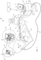
- FIG. 1 is a diagram of an exemplary mapping system 20 in which one or more features of the disclosed subject matter can be implemented.
- Mapping system 20 may include a device, such as a catheter 40, that is configured to obtain electrical activity data in accordance with an exemplary embodiment of the present invention.
- catheter 40 is shown to have a basket shape, it will be understood that a catheter of any shape that includes one or more elements (e.g., electrodes) may be used to implement the exemplary embodiments disclosed herein.
- Mapping system 20 includes a probe 21, having a shaft 22 that may be navigated by a medical professional 30 into a body part, such as heart 26, of a patient 28 lying on a table 29. As shown in FIG.
- medical professional 30 may insert shaft 22 through a sheath 23, while manipulating the distal end of shaft 22 using a manipulator 32 near the proximal end of the catheter and/or deflection from the sheath 23.
- catheter 40 may be fitted at the distal end of shaft 22.
- Catheter 40 may be inserted through sheath 23 in a collapsed state and may be then expanded within heart 26.
- the catheter 40 may be configured to obtain electrical activity within an intra-cardiac chamber of the heart 26.
- Inset 45 shows catheter 40 in an enlarged view, inside a cardiac chamber of heart 26.
- catheter 40 may include an array of elements (e.g., electrodes 48) coupled onto splines that form the shape of the catheter 40.
- the elements e.g., electrodes 48
- the elements may be any elements configured to obtain electrical activity and may be electrodes, transducers, or one or more other elements. It will be understood that although one catheter 40 is shown, multiple catheters may be used to collect electrical activity of an intra-body organ such as the heart 26.
- electrical activity may be any applicable electrical signals that may be measured based on one or more thresholds and may be sensed and/or augmented based on signal to noise ratios and/or other filters.
- a catheter such as catheter 40 may also be configured to sense additional biometric data in addition to electrical activity.
- the data collected by catheter 40 may include one or more of local activation times (LATs), topology, bipolar mapping, unipolar mapping, body surface electrode-based mapping, dominant frequency, impedance, or the like. Further, the catheter 40 may be used to obtain spatial information about an intra-body organ. Local activation times may be points in time of a threshold activity corresponding to a local activation, calculated based on a normalized initial starting point.
- a topology may correspond to the physical structure of a body part or a portion of a body part and may correspond to changes in the physical structure relative to different parts of the body part or relative to different body parts.
- a dominant frequency may be a frequency or a range of frequencies that is prevalent at a portion of a body part and may be different in different portions of the same body part.
- the dominant frequency of a pulmonary vein of a heart may be different than the dominant frequency of the right atrium of the same heart.
- Impedance may be the resistance measurement at a given area of a body part and may be calculated as a standalone value, based on a frequency, and/or in combination with additional considerations such as blood concentration.
- Console 24 may include a processor 41, such as a general-purpose computer, with suitable front end and interface circuits 38 for transmitting and receiving signals to and from catheter 40, as well as for controlling the other components of mapping system 20.
- processor 41 may be further configured to receive electrical activity data, allocate clusters of points at different times and provide a visual indication from a first cluster of points to a related second cluster of points.
- rendering data may be used to provide the medical professional 30 with a rendering of one or more body parts on a display 27, e.g., a body part rendering 35.
- the processor 41 may be external to the console 24 and may be located, for example, in the catheter, in an external device, in a mobile device, in a cloud-based device, or may be a standalone processor.
- processor 41 may include a general-purpose computer, which may be programmed in software to carry out the functions described herein.
- the software may be downloaded to the general-purpose computer in electronic form, over a network, for example, or it may, alternatively or additionally, be provided and/or stored on non-transitory tangible media, such as magnetic, optical, or electronic memory.
- non-transitory tangible media such as magnetic, optical, or electronic memory.
- mapping system 20 may include additional components, such as elements for sensing biometric patient data, wired or wireless connectors, processing and display devices, or the like.
- a display connected to a processor may be located at a remote location such as a separate hospital or in separate healthcare provider networks.
- the mapping system 20 may be part of a surgical system that is configured to obtain anatomical and electrical measurements of a patient's organ, such as a heart, and performing a cardiac ablation procedure.
- a surgical system is the Carto ® system sold by Biosense Webster.
- the mapping system 20 may also, and optionally, obtain biometric data such as anatomical measurements of the patient's heart using ultrasound, computed tomography (CT), magnetic resonance imaging (MRI) or other medical imaging techniques known in the art.
- the mapping system 20 may obtain electrical measurements using catheters, electrocardiograms (ECGs) or other sensors that measure electrical properties of the heart.
- ECGs electrocardiograms
- the biometric data including anatomical and electrical measurements may then be stored in a local memory 42 of the mapping system 20, as shown in FIG. 1 .
- memory 42 may store biometric data for multiple different modalities at the same time.
- the biometric data may be transmitted to the processor 41 from the memory 42.
- the biometric data may be transmitted to a server 60, which may be local or remote, using a network 62.
- Network 62 may be any network or system generally known in the art such as an intranet, a local area network (LAN), a wide area network (WAN), a metropolitan area network (MAN), a direct connection or series of connections, a cellular telephone network, or any other network or medium capable of facilitating communication between the mapping system 20 and the server 60.
- the network 62 may be wired, wireless or a combination thereof.
- Wired connections may be implemented using Ethernet, Universal Serial Bus (USB), RJ-11 or any other wired connection generally known in the art.
- Wireless connections may be implemented using Wi-Fi, WiMAX, and Bluetooth, infrared, cellular networks, satellite or any other wireless connection methodology generally known in the art. Additionally, several networks may work alone or in communication with each other to facilitate communication in the network 62.
- server 60 may be implemented as a physical server. In other instances, server 60 may be implemented as a virtual server a public cloud computing provider (e.g., Amazon Web Services (AWS) ® ).
- AWS Amazon Web Services
- Control console 24 may be connected, by a cable 39, to body surface electrodes 43, which may include adhesive skin patches that are affixed to the patient 28.
- the processor 41 in conjunction with a current tracking module, may determine position coordinates of the catheter 40 inside the body part (e.g., heart 26) of a patient. The position coordinates may be based on impedances or electromagnetic fields measured between the electrodes 43 and the electrodes 48 or other electromagnetic components of the catheter 40.
- Processor 41 may comprise real-time noise reduction circuitry typically configured as a field programmable gate array (FPGA), followed by an analog-to-digital (A/D) ECG (electrocardiograph) or EMG (electromyogram) signal conversion integrated circuit.
- the processor 41 may pass the signal from an A/D ECG or EMG circuit to another processor and/or can be programmed to perform one or more functions disclosed herein.
- Control console 24 may also include an input/output (I/O) communications interface that enables the control console to transfer signals from, and/or transfer signals to electrodes 48 and electrodes 43.
- I/O input/output
- processor 41 may generate rendering data that enables a display, such as display 27 to render a body part, such as a body part rendering 35 and biometric data of multiple modalities as part of the body part rendering 35.
- processor 41 may facilitate the presentation of a body part rendering 35, including one or more clusters of points that are active at a given time.
- the processor 41 may identify the one or more clusters at the given time as well as one or more other related or unrelated clusters at a subsequent time.
- the processor 41 may also determine a propagation route based on the two or more related clusters of points and provide a visual indication of the propagation route accordingly.
- the electrical activity may be stored in a memory 42 and the processor 41 may have access to the electrical activity stored in memory 42 to determine the clusters of point and the corresponding propagation route(s).
- the propagation route(s) may be provided to a medical professional 30 on a display 27.
- Memory 42 may comprise any suitable volatile and/or non-volatile memory, such as random-access memory or a hard disk drive.
- medical professional 30 may be able to manipulate a body part rendering 35 using one or more input devices such as a touch pad, a mouse, a keyboard, a gesture recognition apparatus, or the like.
- display 27 may include a touchscreen that can be configured to accept inputs from medical professional 30, in addition to presenting a body part rendering 35, including the propagation route(s).
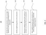
- FIG. 2 shows a process 200 for identifying and marking abnormal activation points, according to exemplary embodiments of the present invention.
- Seed points as referenced herein, are points of an intra-cardiac chamber that exhibit abnormal activations. Such seed points are identified at step 210 of the process 200 with high sensitivity such that true positive rate is emphasized when identifying such seed points.
- the receiver operating characteristics (ROC) curve is adjusted to favor specificity when identifying the seed points at step 210.
- steps 220-240 higher sensitivity is emphasized by identifying neighboring points that exhibit activations at a similar time to the abnormal activations of a corresponding seed point, as further described herein.
- the techniques disclosed herein effectively enlarge the area around the identified seed points by identifying abnormal activations corresponding to the neighboring points.
- the ROC curve is adjusted to favor sensitivity when identifying the neighboring points at steps 220-240.
- the result of the process 200 is to identify abnormal activation areas of endocardiac or epicardiac tissue with a high level of specificity (e.g., through step 210) and a high level of sensitivity (e.g., through steps 220-240).
- one or more abnormal activation points are identified with a high level of specificity.
- the abnormal activation points identified at step 210 may be referred to as seed points to distinguish them from neighboring points that are also identified as having abnormal activations, as further disclosed herein.
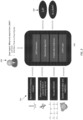
- FIG. 3 shows inputs 310 (e.g., input information) that may be applied to determine abnormal activation points from an intra-cardiac chamber.
- the inputs 310 may include, but are not limited to, a bipolar ECG of a mapping channel, a distal and/or proximal unipolar ECG of a mapping channel, a multi-lead (e.g., 12 lead) body surface (BS) ECG, special information and neighboring point information, or the like.
- One or more of the inputs 310 may be received by a processor such as processor 41 of FIG. 1 .
- user input 320 may be provided to a processor, such as processor 41 and may include location information for areas to exclude when identifying abnormal activations and may include limits, and/or minimum and maximum voltages.
- the processor may execute one or more techniques 330 (e.g., analysis modules) based on the inputs 310 and/or the user inputs 320.
- the one or more techniques 330 e.g., analysis modules
- the application of the one or more techniques 330 may provide electrical activity 340 which may include LAT values and may also include a determination of whether a point is exhibiting LAVAs.
- FIG. 4 provides additional information regarding application of the inputs 310 of FIG. 3 .
- the QRS detection 410, wavefront activations 420, and fractionation detection 430 of FIG. 4 may be applied, as further provided in FIG. 8 , when determining seed points at step 210 of FIG. 2 .
- QRS detection 410 of FIG. 4 may include a preprocessing step 412 and a QRS detection logic step 414.
- the QRS detection 410 may be based on the electrical activity received from the electrodes of a catheter, such as catheter 40 of FIG. 1 , relative to baseline electrical activity determined using one or more BS electrodes attached external to a patient's body.
- the processor such as processor 41, may receive baseline electrical activity from a number (e.g., twelve) of BS electrodes and may extract QRS signals based on comparing the electrical activity received from the electrodes of a catheter to the baseline electrical activity.
- electrical activity measurements within a given amount of time (e.g., 150ms) around a reference annotation may be collected.
- a high pass filter and/or a low pass filter may be applied to the received electrical activity.
- the high pass filter may be applied with a 0.5Hz threshold and the low pass filter may be applied with a 120Hz threshold.
- QRS signals may be determined based on the change in voltage over time of the received electrical activity as provided during the preprocessing step 412.
- An additional low pass filter may be applied using median measurements within a window of time (e.g., 21ms). Voltages with a peak to peak measurement of greater than a given voltage (e.g., .4mV) may be identified and additional electrical activity for an additional time period (e.g., 20ms before and after the peak) may be observed.
- the QRS detection logic step 414 may provide intervals of the start of a QRS signal and end of QRS signal (StartOfQrs, EndOf(ars). Notably, the intervals may be used in determining whether electrical activity at a point on an intra-cardiac surface exhibits abnormal activations (i.e., is a seed point), as further disclosed herein.
- wavefront activations 420 may be determined based on raw unipolar ECG signals and/or bipolar ECG signals.
- a high pass filter may be applied using median measurements of a given time window (e.g., 121ms window) with a finite impulse response (FIR) filter at a given frequency (10Hz).
- the prepossessing input may be provided to a wavefront logic 424, and a feature extraction step 426 may be applied to the output of the wavefront logic 424.
- the feature extraction step 426 may provide one or more of a unipolar derivative, unipolar activity duration, unipolar amplitude, unipolar duration over amplitude, and/or a bipolar amplitude.
- the output of the feature extraction step 426 may be applied to a fuzzy logic step 428 which results in fuzzy scores as sets of (timestamp, fuzzy score) pairs for given points on an intra-cardiac surface.
- the sets of (timestamp, fuzzy score) pairs may be used in determining whether electrical activity at a point on an intra-cardiac surface exhibits abnormal activations (i.e., is a seed point), as further disclosed herein.
- a fuzzy score may be calculated based on the features including the height, weight and/or slope of a negative deflection of a bipolar signal and features including the height, weight and/or slope of the negative deflection of a unipolar signal. Each such feature may affect the fuzzy score according to a different fuzzy membership function. The iterative fuzzy score of each feature may be multiplied to calculate the final fuzzy score of a given point.
- fractionation detection 430 may be determined based on raw unipolar ECG signals and/or bipolar ECG signals.
- a fractionation window detection step 432 a fractionation window for electrical activity at a point on an intra-cardiac surface may be determined.
- the fractionation window may be determined based on the raw unipolar ECG signals and/or bipolar ECG signals and may be determined based on any applicable technique to detect fractionation windows.
- Such techniques may include, but are not limited to, applying one or more steps such as preprocessing, differentiation and squaring, moving window integration, thresholding, post processing, evaluation with a nonlinear energy operator (NELO), Gaussian low pass filtering, or a combination thereof.
- NELO nonlinear energy operator
- the output of the fractionation window detection step 432 may provide intervals of the start of a fractionation window and the end of a fractionation window (e.g., (StartOfFractionation, EndOfFractionation).
- the intervals of the start of a fractionation window and the end of a fractionation window may be used in determining whether electrical activity at a point on an intra-cardiac surface exhibits abnormal activations (i.e., is a seed point), as further disclosed herein.
- a specific intersection percentage of the fractionation window may be required between two points being compared.
- a processor such as processor 41 of FIG. 1 may determine if electrical activity at a point on an intra-cardiac surface is abnormal based on one or more of a fuzzy score, time consistency, and location consistency.
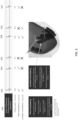
- a fuzzy score As shown in FIG. 5 , for each union of distal and proximal wavefront activations 510, including activations 512, 514, 516, 518, 520, and 522, the processor may determine the fuzzy score, whether time consistency exists between adjacent beats, and whether location consistency exists between neighboring points.
- a threshold fuzzy score (e.g., .65) may be applied such that a calculated fuzzy score for a given point on an intra-cardiac surface corresponds to abnormal electrical activity if it exceeds the threshold fuzzy score.
- time consistency may exist for a detected electrical activation if the activation was present in one or more of the previous cycles.
- the existence of the detected electrical activation in one or more of the previous cycles may indicate that the detected electrical activation is generated by the heart and is not noise.
- Time consistency may be detected if the electrical activation was present in a previous cycle with a tolerance of up to 1% deviation for the previous cycle, a tolerance of up to 2% deviation for two cycles prior to the given electrical activation, and so forth.
- time consistency may exist if electrical activity detected during a given cycle is also present at the same time in a previous cycle with a tolerance deviation of 1% deviation of time in the previous cycle.
- time consistency may exist if electrical activity detected during a given cycle is also present at the same time two cycles prior to the given cycle, with a tolerance amount of 2% deviation of time in the two cycles prior to the given cycle.
- activations 512, 514, 518, and 522 may exhibit time consistency.
- step 220 of the process 200 of FIG. 2 electrical activity of neighboring points within a given threshold distance (e.g., 12mm) of the seed points identified in step 210, may be identified.
- a determination may be made that one or more of the neighboring points exhibit abnormal electrical activity similar to the corresponding seed point identified at step 210.
- the neighboring points that exhibit abnormal electrical activity may be determined based on the same process as applied at step 210, and as disclosed herein.
- the neighboring point(s) that exhibit abnormal activity may be marked as abnormal neighboring points.
- neighboring points may be identified, at step 220, up to a given threshold distance (e.g., 12mm) which may be a constant or may be user-defined.
- the given threshold distance may be the Euclidean distance between two points.
- the given threshold distance may be the shortest path between two points on an intra-cardiac surface as determined, for example, by Dijkstra's algorithm.
- an area or a number of points may be excluded from being considered as seed points and/or abnormal neighboring points. Such area or number of points may be excluded based on user input such as if a user marks anatomical locations and/or points near anatomical locations to be excluded. Such excluded points may be part of a Bundle of His, where a bundle of His includes wide, fast-conducting muscle fibers that carry a cardiac impulse through an insulating annulus fibrosus into the fibrous upper part of the ventricular septum.
- the location consistency indication for neighboring points of a seed point may be determined.
- the location consistency may provide an indication that the abnormal electrical activity exhibited at the seed point is also present at the neighboring points.
- abnormal electrical activity may be expected to be exhibited at a similar time as that of the seed point.
- the tolerance e.g., 1% CL
- the tolerance to consider two activation times as similar times may be a function of the CL such that if the CL is short, less deviation is allowed and if the CL is long then more deviation is allowed.
- a default wavefront velocity of 0.5mm/ms may be applied especially if the actual wavefront velocity is unknown.
- the tolerance of a percentage (e.g., 1%) of a CL may account for deviations in wavefront velocity.
- the wavefront velocity in healthy tissue may be 0.9mm/ms and the wavefront velocity in scar tissue may be 0.1mm/ms.
- activations 512, 518, and 520 may exhibit location consistency such that at least two activations at a similar time are present within neighboring points of the seed point. Notably, location consistency may indicate that the abnormal electrical activity at a seed point is confirmed by the electrical activity of the neighboring points.
- the wavefront velocity may be 1mm/ms.
- the similar time may be a pre-determined value or a user-provided value.
- a neighboring point with electrical activation(s) at a similar time as the seed point may be considered and abnormal neighboring point such that the seed point and the abnormal neighboring point(s) may correspond to an area of complex ECG activations (e.g., LAVAs, fractionations, late potentials, etc.)
- the onset or the center of an activation window may be compared, the threshold may apply to the center, or to the onset of the signal.
- the activation time may be a window and not a single point.
- the duration of activations may also need to be similar when considering similar times of activations.
- the allowed difference in activation times to be considered similar times may be a function of the peak-to-peak voltages such that high a peak-to-peak bipolar voltage may correspond to healthy tissue with a relatively high wavefront velocity, as disclosed herein.
- low peak-to-peak bipolar voltages may correspond to unhealth tissue, such as scar tissue, with a relatively low wavefront velocity, as disclosed herein. Accordingly, for high peak-to-peak voltage areas, the activation times may propagate faster between neighboring points and, conversely, may propagate slower between neighboring points of low peak-to-peak voltage areas.
- the radios to find neighboring points may be defined as a relatively large number, but the ROC may be adjusted to favor less sensitivity and more specificity for points further away from the seed point found in step 210. It will be understood that at any point on the ROC curve, the time of a given activation on a neighboring point is still needed to be at a similar time, as disclosed herein, to a corresponding seed point.
- neighboring points effected by a far field may be removed from the determination of neighboring points at step 230 of the process 200 of FIG. 2 .
- the far field effected neighboring points may be determined by detecting neighboring points within a given radius (e.g., 15mm) from the seed point at 610. For each neighboring point within the given radius, the strongest negative deflection amplitude under the QRS may also be determined at 610.
- An upper value (e.g., 90 th percentile) of the strongest -dV/dt of the neighbors, where the strongest -dV/dt is under the QRS, may be determined at 620.
- a median value of the LAT values of the strongest -dV/dt under the QRS may be identified and this median value may be assumed to be the LAT value of a possible far field at 640.
- the median distance of the neighboring points that contribute to the LAT value determined at 640 may be stored as the far field distance such that the far field distance is the median distance of a percent (e.g., 10%) of the neighboring point with the strongest negative deflection amplitude.
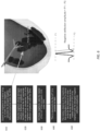
- FIG. 7A shows a diagram of identified seed points 710 with a high specificity, as determined based on step 210 of process 200 of FIG. 2 .
- FIG. 7B shows a diagram of identified neighboring points 720 with electrical activations at similar times as the seed points 710 of FIG. 7A , as determined based on steps 220-240 of process 200 of FIG. 2 .
- the seed points 710 are LAVA points with a high specificity and the neighboring points 720 allow for increased sensitivity and have electrical activations at a similar time as the respective seed points 710.
- FIG. 8 shows variations 810, 820, and 830 for determining the seed points based on step 210 of the process 200 of FIG. 2 .
- the conditions for the temporally latest variation (i.e., from variation 810, 820, and 830) to be met may be applied when identifying a seed point.
- the variations 810, 820, and 830 may utilize the outputs of the QRS detection 410, wavefront activations 420 and fractionation detection 430 of FIG. 4 as inputs.
- a seed point may be identified if the conditions 812 and 814 are met. As shown, a seed point may be identified at variation 810 if the corresponding electrical activity is exhibited after or before QRS, at 812, if time consistency, as discussed in reference to FIG. 5 , is present, and if the fuzzy score corresponding to the electrical activity is greater than a threshold fuzzy score (e.g., .65), at 814.
- a seed point identified based on variation 810 may, for example, have a specificity of 96% and a positive predictive value (PPV) of 72%.
- a seed point may be identified if the conditions 822 and 824 are met.
- a determination may be made if electrical activation at a given point is inside a fractionation window (e.g., if at least two wavefront candidates are present within a fractionation window).
- the seed point may be determined based on the last activation inside the fractionation window, which has a fuzzy score of greater than a threshold fuzzy score (e.g., .65) and if no such activation is present, then the seed point may be determined based on the strongest -dV/dt in the fractionation window.
- a seed point identified based on variation 820 may, for example, have a specificity of 94% and a PPV of 71%.
- a seed point may be identified if the conditions 832 and 834 are met.
- a determination may be made if the electrical activation at a given seed point is under QRS and is not within a fractionation window.
- the seed point may be determined if the electrical activation at the given point is time consistent, as disclosed herein, if the electrical activation is location consistent with neighboring points, if the fuzzy score is above a threshold fuzzy score (e.g., .65), if the slope amplitude between a positive amplitude and an adjacent negative amplitude of a ECG signal (i.e., the negative deflection amplitude) is greater than a given voltage (e.g., 30 ⁇ V), and if the electrical activation at the given point is not a possible far field effect as determined by, for example ((Far Field Distance/Wavefront velocity) + 1% of CL).
- a seed point identified based on variation 830 may, for example, have a specificity of 99% and a
- FIG. 9 shows a process 900 for determining the abnormal neighboring points based on steps 220-240 of the process 200 of FIG. 2 .
- the process 900 may allow for increased sensitivity.
- points within a given radius e.g., 12mm
- a determination whether location consistency exists between the seed point and each of the points identified in step 910 may be made, as described in relation to FIG. 5 .
- the distance between each neighboring point and the seed point may be divided by the wavefront velocity (e.g., 0.5mm/ms).
- a variance may be added to the resulting time (e.g., 1% of the CL).
- a fuzzy score for points for which there is an activation within the time determined by at step 920 may (i.e., where location consistency is present) be determined.
- points for which the fuzzy score exceeds a threshold fuzzy score e.g., .65
- the slope amplitude of the electrical activity for points for which the fuzzy score exceeds the threshold fuzzy score may be identified.
- the points that have a slope amplitude that exceeds a threshold slope amplitude (e.g., 30 ⁇ V) may be determined to be abnormal neighboring points.
- the latest of such activations may be applied when determining the abnormal neighboring points.
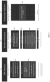
- FIG. 10 shows the experimental results of applying the process 200 of FIG. 2 in accordance with FIGS. 3-9 .
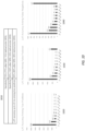
- FIG. 10 is based on the result of a dataset fifteen unique cases and the analysis a total of 41,953 points in accordance with the subject matter disclosed herein.
- table 1010 an average sensitivity of 75% (77% after QRS, 75% before/under QRS) was exhibited across the dataset.
- An average specificity of 83% (100% after QRS, 83% before/after QRS) was exhibited across the dataset.
- the results in table 1010 are provided assuming that the physician is interested in LAVAs in areas of up to 1.5 mV peak -to-peak bipolar amplitudes.
- a LAT accuracy of up to 20ms among true positives was exhibited for 85% (80% after QRS, 88% before/under QRS) for the data set.
- Chart 1020 shows the LAT accuracy among true positives.
- Chart 1030 shows the LAT accuracy among false positives.
- Chart 1040 shows the LAT accuracy among false negatives.
- processors include, by way of example, a general purpose processor, a special purpose processor, a conventional processor, a digital signal processor (DSP), a plurality of microprocessors, one or more microprocessors in association with a DSP core, a controller, a microcontroller, Application Specific Integrated Circuits (ASICs), Field Programmable Gate Arrays (FPGAs) circuits, any other type of integrated circuit (IC), and/or a state machine.
- DSP digital signal processor
- ASICs Application Specific Integrated Circuits
- FPGAs Field Programmable Gate Arrays
- Such processors can be manufactured by configuring a manufacturing process using the results of processed hardware description language (HDL) instructions and other intermediary data including netlists (such instructions capable of being stored on a computer-readable media).
- HDL hardware description language
- netlists such instructions capable of being stored on a computer-readable media.
- the results of such processing can be maskworks that are then used in a semiconductor manufacturing process to manufacture a processor which implements features of the disclosure.
- Non-transitory computer-readable storage mediums include a read only memory (ROM), a random access memory (RAM), a register, cache memory, semiconductor memory devices, magnetic media such as internal hard disks and removable disks, magneto-optical media, and optical media such as CD-ROM disks, and digital versatile disks (DVDs).
- ROM read only memory
- RAM random access memory
- register cache memory
- semiconductor memory devices magnetic media such as internal hard disks and removable disks, magneto-optical media, and optical media such as CD-ROM disks, and digital versatile disks (DVDs).
Landscapes
- Health & Medical Sciences (AREA)
- Life Sciences & Earth Sciences (AREA)
- Engineering & Computer Science (AREA)
- Cardiology (AREA)
- Public Health (AREA)
- Medical Informatics (AREA)
- Biomedical Technology (AREA)
- General Health & Medical Sciences (AREA)
- Physics & Mathematics (AREA)
- Surgery (AREA)
- Pathology (AREA)
- Molecular Biology (AREA)
- Animal Behavior & Ethology (AREA)
- Heart & Thoracic Surgery (AREA)
- Veterinary Medicine (AREA)
- Biophysics (AREA)
- Primary Health Care (AREA)
- Artificial Intelligence (AREA)
- Epidemiology (AREA)
- Signal Processing (AREA)
- Nuclear Medicine, Radiotherapy & Molecular Imaging (AREA)
- Psychiatry (AREA)
- Computer Vision & Pattern Recognition (AREA)
- Physiology (AREA)
- General Business, Economics & Management (AREA)
- Fuzzy Systems (AREA)
- Business, Economics & Management (AREA)
- Mathematical Physics (AREA)
- Evolutionary Computation (AREA)
- Radiology & Medical Imaging (AREA)
- Data Mining & Analysis (AREA)
- Urology & Nephrology (AREA)
- Databases & Information Systems (AREA)
- Measurement And Recording Of Electrical Phenomena And Electrical Characteristics Of The Living Body (AREA)
- Electrotherapy Devices (AREA)
Applications Claiming Priority (2)
| Application Number | Priority Date | Filing Date | Title |
|---|---|---|---|
| US16/685,496 US11278233B2 (en) | 2019-11-15 | 2019-11-15 | Method and apparatus to find abnormal activations in intra-cardiac electrocardiograms based on specificity and sensitivity |
| EP20207557.8A EP3821808B1 (fr) | 2019-11-15 | 2020-11-13 | Procédé permettant de trouver des activations anormales dans des électrocardiogrammes intracardiaques |
Related Parent Applications (1)
| Application Number | Title | Priority Date | Filing Date |
|---|---|---|---|
| EP20207557.8A Division EP3821808B1 (fr) | 2019-11-15 | 2020-11-13 | Procédé permettant de trouver des activations anormales dans des électrocardiogrammes intracardiaques |
Publications (2)
| Publication Number | Publication Date |
|---|---|
| EP4327746A2 true EP4327746A2 (fr) | 2024-02-28 |
| EP4327746A3 EP4327746A3 (fr) | 2024-05-29 |
Family
ID=73448938
Family Applications (2)
| Application Number | Title | Priority Date | Filing Date |
|---|---|---|---|
| EP20207557.8A Active EP3821808B1 (fr) | 2019-11-15 | 2020-11-13 | Procédé permettant de trouver des activations anormales dans des électrocardiogrammes intracardiaques |
| EP24150903.3A Withdrawn EP4327746A3 (fr) | 2019-11-15 | 2020-11-13 | Procédé de détermination d'activations anormales dans des électrocardiogrammes intracardiaques |
Family Applications Before (1)
| Application Number | Title | Priority Date | Filing Date |
|---|---|---|---|
| EP20207557.8A Active EP3821808B1 (fr) | 2019-11-15 | 2020-11-13 | Procédé permettant de trouver des activations anormales dans des électrocardiogrammes intracardiaques |
Country Status (5)
| Country | Link |
|---|---|
| US (2) | US11278233B2 (fr) |
| EP (2) | EP3821808B1 (fr) |
| JP (1) | JP7779003B2 (fr) |
| CN (1) | CN112890824A (fr) |
| IL (1) | IL278499B2 (fr) |
Families Citing this family (2)
| Publication number | Priority date | Publication date | Assignee | Title |
|---|---|---|---|---|
| US20220068479A1 (en) * | 2020-08-26 | 2022-03-03 | Biosense Webster (Israel) Ltd. | Separating abnormal heart activities into different classes |
| US11484369B2 (en) * | 2020-10-28 | 2022-11-01 | Biosense Webster (Israel) Ltd. | Identifying instances of cardioversion while building a position map |
Family Cites Families (19)
| Publication number | Priority date | Publication date | Assignee | Title |
|---|---|---|---|---|
| JP5956463B2 (ja) | 2010-12-30 | 2016-07-27 | セント・ジュード・メディカル・エイトリアル・フィブリレーション・ディヴィジョン・インコーポレーテッド | 身体組織から電子生理学的データを分析しマッピングするシステム、電子生理学的データを分析するシステムの作動方法及び心臓組織から測定されるデータを分析するカテーテルシステム |
| US8948837B2 (en) | 2011-01-13 | 2015-02-03 | Rhythmia Medical, Inc. | Electroanatomical mapping |
| US8620433B2 (en) * | 2012-02-17 | 2013-12-31 | Medtronic, Inc. | Criteria for optimal electrical resynchronization derived from multipolar leads or multiple electrodes during biventricular pacing |
| US8897863B2 (en) * | 2012-05-03 | 2014-11-25 | University Of Washington Through Its Center For Commercialization | Arrhythmia detection using hidden regularity to improve specificity |
| EP2945531B1 (fr) * | 2013-01-17 | 2019-09-04 | CardioInsight Technologies, Inc. | Identification et mappage de point focal |
| MX2017013027A (es) * | 2015-04-14 | 2017-12-08 | Koninklijke Philips Nv | Metodo y sistema para deteccion de isquemia cardiaca basada en electrocardiograma. |
| US10398331B2 (en) | 2015-12-04 | 2019-09-03 | St. Jude Medical, Cardiology Division, Inc. | Methods and systems for statistically analyzing electrograms for local abnormal ventricular activities and mapping the same |
| US10314542B2 (en) * | 2016-01-14 | 2019-06-11 | Biosense Webster (Israel) Ltd. | Identification of fractionated signals |
| EP3402395B1 (fr) * | 2016-01-16 | 2023-08-02 | ZOLL Medical Corporation | Identification rapide de rythmes choquables ou non choquables dans des données ecg |
| US10136828B2 (en) * | 2016-03-31 | 2018-11-27 | Biosense Webster (Israel) Ltd. | Mapping of atrial fibrillation |
| EP3451904B1 (fr) | 2016-05-03 | 2023-12-20 | CardioInsight Technologies, Inc. | Détection de synchronisation de conduction |
| US10383534B2 (en) | 2016-08-11 | 2019-08-20 | Biosense Webster (Israel) Ltd. | Annotation of a wavefront |
| US10143395B2 (en) * | 2016-09-28 | 2018-12-04 | Medtronic Monitoring, Inc. | System and method for cardiac monitoring using rate-based sensitivity levels |
| EP3318210A1 (fr) * | 2016-11-08 | 2018-05-09 | Cardiomed Consulting Ltd | Système de surveillance de l'ablation de tissu cardiaque en étroite proximité avec le noeud av du coeur et pour générer une alerte sensorielle |
| IL257050B (en) * | 2017-01-25 | 2021-04-29 | Biosense Webster Israel Ltd | Analysis and mapping of EKG signals and detection of ablation points for the purpose of eliminating Brugada syndrome |
| EP3642743B1 (fr) * | 2017-06-19 | 2021-11-17 | Viz.ai, Inc. | Procédé et système de triage assisté par ordinateur |
| US11284826B2 (en) * | 2017-09-06 | 2022-03-29 | Queen's University At Kingston | Methods for identifying wave break during atrial fibrillation |
| GB2573109B (en) * | 2018-04-23 | 2022-09-14 | Barts Health Nhs Trust | Methods and systems useful in mapping heart rhythm abnormalities |
| US11445935B2 (en) * | 2018-11-26 | 2022-09-20 | Biosense Webster (Israel) Ltd. | Finding the origin of an arrythmia |
-
2019
- 2019-11-15 US US16/685,496 patent/US11278233B2/en active Active
-
2020
- 2020-11-04 IL IL278499A patent/IL278499B2/en unknown
- 2020-11-13 EP EP20207557.8A patent/EP3821808B1/fr active Active
- 2020-11-13 EP EP24150903.3A patent/EP4327746A3/fr not_active Withdrawn
- 2020-11-13 CN CN202011269174.XA patent/CN112890824A/zh active Pending
- 2020-11-13 JP JP2020189224A patent/JP7779003B2/ja active Active
-
2022
- 2022-03-18 US US17/698,578 patent/US20220202345A1/en active Pending
Also Published As
| Publication number | Publication date |
|---|---|
| US20210145301A1 (en) | 2021-05-20 |
| IL278499B2 (en) | 2023-12-01 |
| US20220202345A1 (en) | 2022-06-30 |
| US11278233B2 (en) | 2022-03-22 |
| EP3821808B1 (fr) | 2024-01-10 |
| EP4327746A3 (fr) | 2024-05-29 |
| JP7779003B2 (ja) | 2025-12-03 |
| JP2021079099A (ja) | 2021-05-27 |
| CN112890824A (zh) | 2021-06-04 |
| IL278499A (en) | 2021-05-31 |
| EP3821808C0 (fr) | 2024-01-10 |
| EP3821808A1 (fr) | 2021-05-19 |
| IL278499B1 (en) | 2023-08-01 |
Similar Documents
| Publication | Publication Date | Title |
|---|---|---|
| US12543994B2 (en) | Intracardiac unipolar far field cancelation using multiple electrode cathethers | |
| JP2016508057A (ja) | 解剖学的構造をマッピングするための回復曲線を推定するカテーテルシステム | |
| WO2023105493A1 (fr) | Système et cathéter de visualisation d'ablation de veine cardiaque | |
| US20220202345A1 (en) | Method and apparatus to find abnormal activations in intra-cardiac electrocardiograms based on specificity and sensitivity | |
| EP4032471A1 (fr) | Détermination automatique de stabilité de cathéter | |
| EP3834719B1 (fr) | Indication de proximité de tissu sur la base d'un sous-ensemble d'électrodes | |
| JP7830098B2 (ja) | 解剖学的構造マッピングデータの信号及び補正処理 | |
| JP2025502643A (ja) | 多電極カテーテルを使用する心臓内単極遠方界消去 | |
| JP2022167891A (ja) | リエントリ回路を引き起こす心室頻脈の擬似興奮マップによる視覚化 | |
| US20220181025A1 (en) | Setting an automatic window of interest based on a learning data analysis | |
| US12458438B2 (en) | Cardiac vein ablation visualization system and catheter | |
| EP4023154A1 (fr) | Validation post-ablation par signal visuel | |
| US11607272B2 (en) | Visual route indication for activation clusters | |
| US20220193422A1 (en) | Automatic post pacing interval measurement and display | |
| CN118382394A (zh) | 使用多电极导管的心内单极远场消除 |
Legal Events
| Date | Code | Title | Description |
|---|---|---|---|
| PUAI | Public reference made under article 153(3) epc to a published international application that has entered the european phase |
Free format text: ORIGINAL CODE: 0009012 |
|
| STAA | Information on the status of an ep patent application or granted ep patent |
Free format text: STATUS: THE APPLICATION HAS BEEN PUBLISHED |
|
| AC | Divisional application: reference to earlier application |
Ref document number: 3821808 Country of ref document: EP Kind code of ref document: P |
|
| AK | Designated contracting states |
Kind code of ref document: A2 Designated state(s): AL AT BE BG CH CY CZ DE DK EE ES FI FR GB GR HR HU IE IS IT LI LT LU LV MC MK MT NL NO PL PT RO RS SE SI SK SM TR |
|
| PUAL | Search report despatched |
Free format text: ORIGINAL CODE: 0009013 |
|
| AK | Designated contracting states |
Kind code of ref document: A3 Designated state(s): AL AT BE BG CH CY CZ DE DK EE ES FI FR GB GR HR HU IE IS IT LI LT LU LV MC MK MT NL NO PL PT RO RS SE SI SK SM TR |
|
| RIC1 | Information provided on ipc code assigned before grant |
Ipc: G16H 50/20 20180101ALI20240422BHEP Ipc: A61B 5/00 20060101ALI20240422BHEP Ipc: A61B 5/349 20210101AFI20240422BHEP |
|
| STAA | Information on the status of an ep patent application or granted ep patent |
Free format text: STATUS: THE APPLICATION IS DEEMED TO BE WITHDRAWN |
|
| 18D | Application deemed to be withdrawn |
Effective date: 20241130 |