EP4328536A2 - Dispositif d'analyse d'arme à feu - Google Patents
Dispositif d'analyse d'arme à feu Download PDFInfo
- Publication number
- EP4328536A2 EP4328536A2 EP24151898.4A EP24151898A EP4328536A2 EP 4328536 A2 EP4328536 A2 EP 4328536A2 EP 24151898 A EP24151898 A EP 24151898A EP 4328536 A2 EP4328536 A2 EP 4328536A2
- Authority
- EP
- European Patent Office
- Prior art keywords
- signal
- voltage
- firearm
- time
- coil
- Prior art date
- Legal status (The legal status is an assumption and is not a legal conclusion. Google has not performed a legal analysis and makes no representation as to the accuracy of the status listed.)
- Granted
Links
Images



Classifications
-
- F—MECHANICAL ENGINEERING; LIGHTING; HEATING; WEAPONS; BLASTING
- F41—WEAPONS
- F41A—FUNCTIONAL FEATURES OR DETAILS COMMON TO BOTH SMALLARMS AND ORDNANCE, e.g. CANNONS; MOUNTINGS FOR SMALLARMS OR ORDNANCE
- F41A31/00—Testing arrangements
-
- F—MECHANICAL ENGINEERING; LIGHTING; HEATING; WEAPONS; BLASTING
- F41—WEAPONS
- F41A—FUNCTIONAL FEATURES OR DETAILS COMMON TO BOTH SMALLARMS AND ORDNANCE, e.g. CANNONS; MOUNTINGS FOR SMALLARMS OR ORDNANCE
- F41A19/00—Firing or trigger mechanisms; Cocking mechanisms
- F41A19/01—Counting means indicating the number of shots fired
-
- G—PHYSICS
- G01—MEASURING; TESTING
- G01P—MEASURING LINEAR OR ANGULAR SPEED, ACCELERATION, DECELERATION, OR SHOCK; INDICATING PRESENCE, ABSENCE, OR DIRECTION, OF MOVEMENT
- G01P3/00—Measuring linear or angular speed; Measuring differences of linear or angular speeds
- G01P3/64—Devices characterised by the determination of the time taken to traverse a fixed distance
- G01P3/66—Devices characterised by the determination of the time taken to traverse a fixed distance using electric or magnetic means
-
- G—PHYSICS
- G01—MEASURING; TESTING
- G01R—MEASURING ELECTRIC VARIABLES; MEASURING MAGNETIC VARIABLES
- G01R19/00—Arrangements for measuring currents or voltages or for indicating presence or sign thereof
- G01R19/165—Indicating that current or voltage is either above or below a predetermined value or within or outside a predetermined range of values
- G01R19/16533—Indicating that current or voltage is either above or below a predetermined value or within or outside a predetermined range of values characterised by the application
- G01R19/16538—Indicating that current or voltage is either above or below a predetermined value or within or outside a predetermined range of values characterised by the application in AC or DC supplies
Definitions
- the invention relates to a firearm analysis device for determining parameters indicative of a firearm from a shot and a corresponding firearm analysis method for determining parameters indicative of a firearm from a shot using such a firearm analysis device.
- the invention also includes a firearm comprising a firearm analysis device.
- the invention also includes a computer program product which contains computer-readable instructions for carrying out some of the method steps.
- position designations such as “top”, “bottom”, “left”, “right”, “front”, “back”, etc. refer to a firearm held in a normal firing position, in which the axis of the core runs horizontally and the shot is fired in front away from the shooter.
- shot counters which count the number of shots fired using electrical signals.
- the signals consist of electrical voltages that are induced by a magnet-coil arrangement built into the weapon when a shot is fired.
- US 8,046,946 B2 (Packer Engineering, Inc. ) discloses a shot counter device for a firearm consisting of a specific magnet-coil arrangement.
- the coil is formed here by continuous wire windings, which have a reversing loop on non-magnetizable elements, whereby the induced voltages of adjacent magnetizable coil elements add up. Due to this structure, the field currents induced by the movable bar magnets sweeping across the field accumulate and add up into one maximum, rectified total current. The resulting signal serves as the basis for determining the number of shots fired.
- EP 3 140 605 B1 (Heckler & Koch GmbH ) discloses a battery-free shot counter with a magnet-coil arrangement in which alternately polarized permanent magnets sweep over a coil with a soft magnetic core when the shutter moves back and forth.
- the coil winding surrounds the soft magnetic prong-shaped core or one of its prongs.
- the coil described does not have any reversal loops and by using the prongs, no voltages are added, but the magnetic fields are added up, that is, the permanent magnets generate a sequence of voltage pulses with oppositely aligned voltage amplitudes when they sweep over the coil, i.e. a (non-added) alternating voltage.
- This signal makes it possible, based on the additional phase information obtained in this way, to distinguish between the number of shots fired and between the forward and backward movement of the shutter.
- conclusions can be drawn about the wear and tear of a firearm using the information obtained from known shot counters about the firing of a firearm.
- One aspect of the invention relates to a firearm analysis device for determining parameters indicative/characteristic of a firearm from a shot.
- the firearm analysis device can also be a firearm diagnostic device.
- the firearm analysis device includes, for example, a voltage generation unit, a signal processing unit, a signal evaluation unit and a time determination unit.
- the voltage generating unit generates an alternating voltage signal when the slide, for example, moves back and forth caused by a shot being fired. If necessary, this is pre-processed in the signal processing unit to form a usable measurement signal, for example by an analog-digital converter (ADC) or a rectifier circuit.
- ADC analog-digital converter
- the signal evaluation unit analyzes the measurement signal and uses it to determine information about the weapon and/or the shot. To do this, it may use time information such as time durations that were determined in the time determination unit.
- the voltage generating unit is designed to generate an alternating voltage during a forward and/or backward movement of a movable weapon part, for example the slide of a pistol, when a shot is fired.
- the tension can be generated along a section of the route that the movable weapon part covers when moving backwards or forwards.
- the voltage can be generated using a magnet-coil arrangement, such as in US 8,046,946 B2 (Packer Engineering, Inc.) or in EP 3 140 605 B 1 (Heckler & Koch GmbH) is described.
- EP 3 140 605 B1 known inductively generated alternating voltage signals can be used.
- alternating voltage signals generated in other ways, for example those generated via piezo elements or electromechanical converters, are also conceivable. Regardless of how they are generated, the alternating voltage signals then serve as input signals to the signal processing unit.
- the signal processing unit can be used to convert the generated alternating voltage into a measurement signal that can be used in the other device components.
- the analog AC voltage signal can be provided without preprocessing.
- the measurement signal would be identical to the alternating voltage signal.
- it can also be digitized using an analog-digital converter (ADC) and further pre-processed as an alternative or additional option.
- the signal processing unit can include further suitable switching elements such as filters and rectifiers.
- a reference signal and/or a supply voltage for the downstream signal evaluation unit is additionally generated in the signal processing unit.
- the reference signal can be used, for example, as a dynamic comparison value can be used for analyzing the measurement signal.
- the measurement and/or reference signal is then evaluated in the subsequent signal evaluation unit.
- the signal evaluation unit can, for example, include a microcontroller. It is generally used to evaluate and analyze signals. In particular, it can be used to determine times and parameters such as speed, acceleration, cadences/firing rates or fire modes.
- the signal evaluation unit can be designed, for example, to determine a first and a second point in time during the forward and/or backward movement of the movable weapon part. These can be, for example, certain points in time in the course of the measurement signal, such as the beginning and end of the signal or the beginning and end of a period or half-period within a signal.
- the time determination or time measurement unit is generally used to measure time and can generally determine durations such as signal durations, durations of signal or time segments or distances between individual signals or points in time that are within a signal or are distributed over several signals. In particular, it is used to determine the time intervals between first and second points in time.
- Time determination units can be any device suitable for the relative or absolute determination of durations. E.g. clocks, clock generators in combination with a timer that counts the cycles and knows the time intervals between successive cycles, as well as capacitors whose degree of discharge serves as a measure of elapsed time.
- Another aspect of the invention relates to a firearm that includes a firearm analysis device.
- a further aspect of the invention relates to a method for determining parameters indicative of a firearm from a shot.
- the method can generally be used to determine parameters and other information about firearms and firing. This can be done e.g. B. include: detecting alternating voltages, providing at least one measurement signal based on the alternating voltage, determining at least a first and a second point in time of the forward and / or retrace and determining at least one time period duration, i.e. a duration of through the first and time periods defined at the second point in time.
- the method can use the components of the firearm analysis device described above.
- the alternating voltages may have been generated while a moving weapon part was moving forward or backward when a shot was fired; e.g. from the voltage generating unit described above.
- the measurement signal can be generated based on the generated alternating voltages.
- the first and second times include the examples described above.
- Another aspect of the invention relates to a computer program product that contains computer-readable instructions for carrying out some of the method steps.
- a reference signal is generated from each generated alternating voltage or a signal based thereon; e.g. through a rectifier circuit in the signal processing unit.
- Generating a reference signal has the advantage that it serves as a dynamic reference or threshold value for the measurement signal can serve. Dynamic means that the value for each weapon and even each signal is determined individually at any time. For example, a first point in time and a second point in time can then be determined, for example, by the signal evaluation unit based on a comparison of the measurement and reference signals; e.g. by comparing the time courses.
- This takes advantage of the fact that variations in the amplitude of the alternating voltage signal (e.g. due to variations in the distances between the magnet and the coil or the speeds) change both the amplitude of the reference and the measurement signal, but the ratio of the reference and measurement signals remains the same.
- the voltage generating unit can comprise at least two magnetic poles and a coil.
- the at least two magnetic poles can be arranged one after the other in such a way that they move on a path relative to the coil in response to a shot being fired.
- Successive poles each have polarizations that are opposite to each other.
- the poles can pass through the coil one after the other in such a way that they successively induce oppositely directed voltages in the coil during a return or forward movement.
- Such voltage generating units are easy to manufacture and reliably deliver suitable alternating voltage signals.
- the times are determined according to when the measurement signal exceeds or falls below the reference signal or a threshold value derived therefrom.
- the first point in time can be determined according to when the measurement signal exceeds or falls below the reference signal or a threshold value derived therefrom.
- the second point in time can be determined according to when the measurement signal again exceeds or falls below the reference signal or a threshold value derived therefrom after the first point in time.
- the reference signal therefore serves as the dynamic reference value described above for the analysis of the measurement signal.
- the desired times can be easily determined from the course of the two signals over time.
- the duration of a period of the measurement signal can also be determined. This takes place, for example, in the signal evaluation unit.
- the speed of a part of the firearm that moves back and/or forward is determined based on the measurement signal and the reference signal.
- the first point in time and the second point in time can be determined during a single return or a single forward movement of the movable weapon parts. From the specific period of time defined by these two points in time Time period and a length of a route along which the alternating voltage underlying the measurement signal of this time period is generated during the return or forward travel, the speed of the moving weapon parts can be determined during this time period.
- a corresponding first and a corresponding second position on a route along which the voltage generating unit generates the alternating voltage on which the measurement signal is based can be assigned to the first point in time and the second point in time via the measurement signal.
- the speed is then determined from the duration of the period and the distance between the first and second positions.
- the speed determination can be carried out, for example, by the signal evaluation unit, with the duration being determined, for example, by one of the time determination units. In this way, the speed of the slide, for example, can be determined for each shot, which is advantageous, for example, for monitoring and maintaining the weapon.
- the respective speeds of the movable weapon parts are determined during at least two consecutive time periods; and the acceleration of the moving weapon parts during their return or forward movement is determined from the specific speeds and a time interval between the at least two successive time periods. In this way, the acceleration of the moving weapon parts can also be easily determined from the already existing signal, which allows, for example, conclusions to be drawn about the ammunition used.
- the signal processing unit provides a supply voltage based on the alternating voltages for the operation of the signal evaluation unit. This allows the entire firearm analysis device to be operated without batteries.
- the reference signal is rectified, for example during its generation.
- the signal processing unit includes, for example, a rectifier circuit for rectifying voltages.
- the reference signal can be distinguished from the measurement signal in that it is not or only slightly modulated and/or is non-periodic.
- a rectified reference signal can also advantageously be evaluated by signal evaluation units that can only detect direct currents. This is usually the case with microcontrollers, for example.
- the rectified reference signal can also be used to supply the signal evaluation unit with direct current.
- the measurement signal is half-wave rectified or not rectified during its generation, for example by the signal processing unit. This means that it remains distinguishable from the reference signal, e.g. because it is modulated and/or non-periodic. In addition, it still contains the phase information of the alternating voltage generated.
- the half-wave rectification can be carried out, for example, by the rectifier circuit used to rectify the reference signal or parts thereof.
- the reference signal is also added up during its generation.
- a voltage doubling circuit can be used for this.
- the signal processing unit includes a Delon circuit as a rectifier circuit.
- the Delon circuit also acts as a voltage doubler. This means that the rectified signals are further amplified.
- the time determination unit comprises a timer and a clock source, the timer determining durations over a number of clocks and a time interval between the clocks. In this way, time intervals and durations can be determined in a simple and proven way.
- the time determination unit comprises a capacitor connected to a load, the capacitor being charged during a return and/or forward movement by the alternating voltage generated in the process and the durations being determined via the degree of discharge of the capacitor. This makes it possible to measure time over a certain period of time even if there is no power supply.
- the time interval between individual shots can be determined. For example, by determining the first point in time as the end of a measurement signal generated during a forward run and the second point in time as the beginning of a measurement signal generated during a return run following this forward run. The durations of the time periods defined by the first and second points in time then determine the time interval between individual shots. Based on the duration of the time period defined by the first point in time and the second point in time, it can then be determined whether a shot was fired in continuous or single fire. This can be done, for example, in the signal evaluation unit.
- continuous fire occurs when the time interval between the multiple advances or the multiple returns of moving weapon parts is below a time or voltage limit value, and otherwise that there is an individual fire. Further conditions can be used as a criterion for the existence of continuous fire, for example that the firearm can be fired in continuous fire and/or that several forward and backward movements have been detected. In this way, information about the load on the weapon can be accessed in a reliable and simple manner, for example for maintenance purposes.
- time interval intervals are defined based on the time interval limit and/or a further time interval limit. Based on this, at least two different firing rates are determined in single fire and/or in continuous fire. The determination is made based on which of these time intervals the time interval duration lies in. All of this can be done, for example, in the signal evaluation unit. This has the advantage that more detailed information is accessible, for example for maintenance.
- the measurement signal is digitized. E.g. it can be converted into a binary signal. This can be done, for example, by the signal evaluation unit. If a reference signal is present, it can be converted into a digital measurement signal according to the following rule: where U0 ⁇ min (reference signal).
- the phase information can be converted into a binary signal that can be read quickly and easily, with which, for example, rewind and forward can be encoded.
- the distinction between the running direction can be checked via the binary signal or the resulting coding.
- the voltage generation unit uniquely encodes the alternating voltage it generates on the movable weapon part. For example, it can generate a signal that clearly identifies the moving weapon part.
- the magnets can be arranged in the movable weapon part and the The number of magnets can be indicative of the movable weapon part. In this way, additional information about the shots fired and the weapons can be easily obtained from the signal.
- the digital measurement signal is used to determine first and second points in time. For example, a first time is determined after when the digital measurement signal changes from “0" or “empty” to "1", and a second time is determined after when the digital measurement signal changes from “1” or "empty” to “0". .
- the first and second points in time can thus advantageously also be determined from the digital measurement signal.
- the digital measurement signal is used to determine whether a backward or forward movement has taken place. For example, based on the sequence of signal sections in which the digital measurement signal is continuously "1" or "0", it can be determined whether the measurement signal is based on a forward or backward movement of the moving weapon parts, e.g. by the signal evaluation unit. In this way, additional information can be obtained from the digital signal in a simple and reliable way.
- Another embodiment includes a clock to determine the time and/or date of a shot.
- a logbook can be kept with the date and time of weapon use and the data obtained from it.
- a further embodiment comprises an acceleration sensor by means of which the acceleration of the forward and/or backward movement of the movable weapon parts can be determined.
- the acceleration of the moving weapon parts can be determined in a simple and proven way, which allows, for example, conclusions to be drawn about the ammunition used.
- the firearm analysis devices described below are generally suitable for analyzing and counting shots and other movements of weapon parts. For example, shutter movements when manually loading or unloading a firearm can also be recorded, analyzed and, if desired, counted.
- indicative parameters are determined for the firearm, in particular for movement of parts of the firearm. This includes, for example, parameters such as the number of shots, the time and date of the shot, the duration of the shot and Speed, acceleration and time intervals of movements of weapon parts. Furthermore, cadences and fire modes (continuous fire, single fire) can be determined.
- the firearms can be, for example, handguns or long guns.
- breechblocks and slides serve as examples of weapon parts that move when fired
- grips or weapon housing elements serve as examples of stationary weapon parts.
- all weapon parts that move relative to one another when a shot is fired can be used to generate a signal.
- this includes, on the one hand, parts that move during loading or another comparable event and, on the other hand, parts that remain stationary relative to them.
- the determined parameters also provide specific information about the respective moving weapon parts and the firearm analysis devices can therefore also serve as a sensor for data about the corresponding weapon parts, e.g. the slide.
- the voltage generating unit may have alternately polarized permanent magnets, which are arranged in a row in a movable part of the firearm, for example in the slide or breech of the firearm.
- the permanent magnets move with their alternating pole ends on a path relative to a stationary coil with a soft magnetic core, for example arranged in the handle of the firearm.
- the permanent magnets pass through the coil one after the other and, due to the alternating polarity, induce an alternating voltage signal.
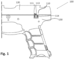
- the voltage generating unit 110 shown there therefore comprises, for example, a first magnetic pole 113, a second magnetic pole 111 and a coil 114.
- the first and second magnetic poles 111, 113 are arranged one after the other in such a way that they have opposite polarizations and they are move on a path relative to the coil 114 in response to a shot being fired. They pass through the coil one after the other in such a way that they successively induce voltages with opposite signs in the coil during a rewind or forward movement.
- the first and second magnetic poles 113, 111 are arranged here in the slide 120 of the firearm 100.
- the soft magnetic core and the coil 114 are arranged in the handle 130.
- the soft magnetic core is designed with three prongs and the coil 114 is wound around the middle prong.
- any arrangement of two or more alternatingly polarized permanent magnets is suitable.
- the arrangement can consist of an even number of 2N permanent magnets.
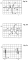
- the Characters. 2a and 2b show examples of such voltage curves for return and forward movement ( FIG. 2a or 2b); here for the case of two permanent magnets and a coil with a soft magnetic core.
- Fig. 2a is a representation of the time curve of the voltage U(t) of the voltage between a first coil connection and a second coil connection during a shutter return caused by a shot being fired.
- the amplitude of the second voltage amplitude U2 is at least one and a half times as large as the amplitude of the first voltage amplitude U1.
- the amplitude of the third voltage deflection U3 is significantly smaller than the amplitude of the second voltage deflection U2.
- the amplitude of the second voltage amplitude U2 is at least one and a half times as large as the amplitude of the third voltage amplitude U3. After the third voltage swing U3, the voltage returns to the permanent voltage value U0.
- the voltage curve U(t) also shows smaller voltage fluctuations U01, U30.
- the first smaller voltage excursion U01 occurs when the first magnet 113 passes the front tine without coil windings.
- the second smaller voltage excursion U30 occurs when the second magnet 111 passes the rear tine without coil windings.
- the forward and backward signals also differ quantitatively in the magnitudes of the amplitudes and their durations.
- the signal resulting from a shutter rewind can be seen within a first time range t1 and the signal resulting from a shutter advance can be seen in a second, later time range t2.
- t1 is shorter than t2. This is because the return of the slide, caused directly by the firing of the shot, occurs at a higher speed than the forward movement caused by the shutter spring. The faster return also ensures faster changes in the magnetic field and thus higher induced voltages. Therefore, the voltage value U2 is also higher than the voltage value U5.
- Signals induced in this way can then be fed to a signal evaluation unit, for example consisting of a microcontroller, for analysis.
- a signal evaluation unit for example consisting of a microcontroller
- the signals can be further or pre-processed in one or more signal processing units, such as filter, rectifier or amplifier circuits.
- the signal can also be extended accordingly.
- a longer signal can be amplified, for example, by a circuit that accumulates the voltage.
- a correspondingly long-lasting and strong signal can then also be used to supply power to other components, e.g. e-paper displays.
- permanent sliding contacts or spring-loaded contacting signal generating elements can be used. They would keep the distances between the permanent core and the coil core and thus their tolerances, which are included in the signal intensity as the square of their distances, sufficiently constant and also low. In practice, however, this would require considerable additional design effort.
- a technically advantageous solution for increasing the induced voltages is to arrange several rows of permanent magnets in parallel, i.e. next to each other.
- they can be 2N permanent magnets.
- FIG 1 The explained coil with a three-pronged, soft magnetic core would be rotated by 90° in this case. So, for example, occur at the in FIG. 1
- the magnets can be attached in several parallel rows with alternating polarities on the movable part of the shot counter device.
- FIGS. 3a-d show some examples of the arrangement of a coil with a three-pronged magnetizable core and a series of alternatingly polarized permanent magnets.
- the signal can be amplified and lengthened by extending the series with additional soft magnets.
- the induced voltage such as in EP 3 140 605 B1 (Heckler & Koch GmbH ) explained, also used to operate the signal evaluation unit, for example a microcontroller
- the duration of the available operating voltage depends on the number of magnets arranged one behind the other. The more magnets are arranged one behind the other, the longer the signal duration and thus the duration of the available operating voltage for signal processing.
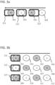
- FIG. 3a shows schematically four alternatingly polarized permanent magnets 301 - 304 arranged in series, which sweep over a coil with a three-pronged core.
- the tines 321 - 323 are arranged in a horizontal direction.
- Each rectangle represents a tine 321 - 323 in a top view.
- the magnets sweep over the coil in the direction of the arrow. By arranging the magnets in a row, the induced signal is extended, but not amplified.
- FIG. 3b shows schematically an arrangement in which the rows of permanent magnets are arranged in a vertical direction, i.e. parallel.
- the three-pronged core coil is here rotated through 90° so that the prongs 321 - 323 are arranged along the vertical direction.
- the tines of the core are simultaneously swept over by three magnets. This increases the field strengths of the magnetic fields generated in the core. This also increases the voltages induced in the coil and thus the signal strengths. In this way, there can be larger distances between the permanent magnet and the coil without the signal being too weak.
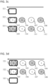
- 3c and 3d show schematic variations of the in FIG 3b Arrangement shown with only two rows or eight permanent magnets.
- the specific arrangement of the permanent magnets can also serve, for example, to identify the weapon parts in or on which they are arranged.
- different closure systems can be coded and thus identified by a corresponding selection of permanent magnets and lengths of permanent magnet arrangements.
- FX or UTM practice locking systems are used, whose locks differ from the standard locks for live fire. This could, for example, have longer or shorter arrangements of permanent magnets.
- the standard shutter may include four permanent magnets while the over-shutter includes five or six. Another way to differentiate is to use magnets of different sizes and strengths and to code different closures over them. Both approaches can also be combined.
- an odd number 2N+1 of magnets can be used and the additional (2N+1) magnet can be chosen to be significantly smaller or weaker, or its distance from the magnet in front of it does not correspond to the distance between the remaining magnets.
- the signal from this magnet can be recognized in the overall signal, so that despite the odd number of Magnets allow the distinction between forward and reverse travel.
- a reference signal can be generated, which can be used, for example, as a dynamic threshold value that depends on the time course and the individual geometries. This and other aspects of the invention will be explained below.
- FIG. 4 shows a block diagram of an example circuit for generating a measurement voltage IN, and optionally an additional reference voltage V in , which are supplied to a signal evaluation unit 420.
- An alternating voltage U e is generated by a voltage generating unit 401, inductively in this example by a coil.
- Measurement and reference signals are generated from this in a signal processing unit 410.
- the signal processing unit 410 can, for example, consist only of an ADC and a rectifier circuit for rectifying voltages and/or include further elements.
- the measurement signal IN + can be half-wave rectified and the reference signal V in can be rectified.
- signals that can be processed by the signal evaluation unit 420 can then be generated from the IN+ and Vin and these can be evaluated in the signal evaluation unit 420.
- one or more time determination units 450 may be provided. These can be used to measure the times that have passed between different points in time.
- one of the time determination units comprises e.g. B. an internal or external clock source in combination with a timer.
- the timer counts the cycles and knows the time intervals between the individual cycles. He can then calculate a time from this.
- One of the time determination units can also include a capacitor that discharges in a defined manner via a load.
- the capacitor charges electrically with each shot signal via the alternating voltage U e generated and then rectified during a return and/or forward movement and discharges in a defined manner via the load, for example a resistor.
- the capacitor discharges continuously via the load even when the signal evaluation unit 420 no longer has any operating voltage available.
- the signal evaluation unit 420 is supplied with a supply voltage again after a shot, it measures the voltage on the capacitor using an analog-digital converter and evaluates it these out.
- the time intervals/durations are estimated via the degree of discharge of the capacitor or the voltage across the capacitor.
- a supply voltage V cc for operating the signal evaluation unit 420 and the time calculation unit 450 can be generated from the output voltage U e .
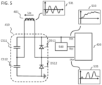
- FIG. 5 shows an exemplary embodiment in which the signal processing unit 410 has a voltage multiplier circuit, in particular a signal doubling circuit, in particular a Delon circuit, for rectification.
- a voltage multiplier circuit in particular a signal doubling circuit, in particular a Delon circuit, for rectification.
- FIG. 6 shows such a Delon circuit 600.
- the Delon circuit consists of two diodes D1 and D2 (half-wave rectifier circuits), as well as two capacitors C1 and C2, which are followed by a load (not shown). If a time-limited alternating voltage signal (e.g. one induced when a shot is fired) U e is coupled into the Delon circuit, the following happens:
- the diode D1 generates a pulsating direct voltage from the positive half-wave of the alternating voltage signal U e .
- the diode D2 generates a pulsating direct voltage from the negative half-wave of the alternating voltage signal.
- the reverse voltage of the two diodes D1 and D2 must be at least twice as large as the peak value of the coupled AC voltage signal.
- the two capacitors C1 and C2 are thereby charged alternately, almost to the peak value of the alternating voltage signal U e .
- the rectified voltage U a at the output of the Delon circuit is then approximately twice as large as the peak value of the injected alternating voltage signal in the unloaded case.
- an alternating voltage U e is induced in the coil.
- the signal that can be measured directly at the coil 401 as alternating voltage U e is referred to as the base signal/output signal IN 0 .
- the qualitative course of IN 0 is shown in plot 531.
- the measurement signal IN and the reference signal V in are then generated from IN 0 in the signal processing unit 410.
- the qualitative curves of IN, and V in are shown in plots 533 and 535.
- an operating voltage V cc for operating the signal evaluation unit 420 is generated with the aid of a linear regulator 540.
- the voltage is tapped via both diodes D511 and D512. It therefore corresponds to the sum of the capacitors C511 and C512 applied voltages and would theoretically increase with each half-wave until both capacitors are fully charged.
- the base signal IN 0 is therefore rectified and added in the usual way on the Delon circuit. Theoretically, the voltage would ultimately be doubled.
- ⁇ U voltage loss dependent on the diode
- the reference signal V in can further be reduced to a lower voltage using a voltage divider following the Delon circuit.
- the base signal IN 0 is half-wave rectified in the signal processing unit 410, with further signal processing steps being possible before or after.
- a pulsating signal IN is generated from the alternating voltage signal IN 0 , into which only the half-waves with negative or positive voltage amplitudes are included.
- the measurement signal IN + is tapped for the measurement signal IN + .
- the measurement signal IN + can be brought to a lower voltage using a voltage divider, not shown here.
- the ratio of the resistances of the voltage divider must be chosen so that the peak value of IN, does not become greater than the supply voltage V cc , in order to ensure that the signal IN, lies within the voltage range recognized by the ADC.
- the voltage tapped across the two diodes D511 and D512, or across the two capacitors C511 and C512, is also regulated to an operating voltage V cc , for example 3.3 V, by means of the linear regulator 540.
- V cc is then used to operate the signal evaluation unit, which can in particular include a microcontroller.
- the signal evaluation unit becomes active and measures the voltages IN + and V in . This measurement can be carried out, for example, via an internal analog-digital converter (ADC) in the signal evaluation unit.
- ADC analog-digital converter
- V cc There is a voltage interval of V cc within which the shutter movement is detected.
- the electricity generation that continues after this interval and after the detection has been completed is used to operate the signal evaluation unit and the devices assigned to it until all predetermined shot analysis functions have been completed.
- the length of this interval is determined by the point in time at which the signal evaluation unit 420 receives enough energy to begin signal sampling and evaluation and the point in time at which the measurement signal definitely falls below the reference signal. This point in time is reached when the time intervals between the amplitude lows and amplitude peaks, i.e. the edge widths between these amplitude positions, are exceeded by a certain period of time (e.g. twice the duration of the two largest edge widths is exceeded).
- V in passes through a voltage divider
- the ratio of the resistances of the voltage divider must be selected so that the peak value of V in does not become greater than the supply voltage V cc . This ensures, for example, that the signal V in for the sampling lies within a voltage range that can be recognized, for example by an ADC of the signal evaluation unit 420.
- FIG. 7 now graphically shows how, from a comparison of the measurement signal IN + and the reference signal V, times are determined that are indicative, for example, of a forward or backward movement of the breech of a weapon.
- the measurement signal only needs to oscillate and not necessarily, as in FIG.7 shown to be half-wave rectified.
- the measurement signal can therefore fundamentally also include half-waves with negative and positive half-waves.
- the times t701 - t706 and t711 - t714 shown are determined as follows: At times t701, t703 and t705, the measurement signal IN exceeds the reference signal V in . In the in FIG. 7 In the signal curves shown, this corresponds to the points at which the initially smaller measurement signal crosses the initially larger reference signal. At times t702, t704 and t706, the measurement signal falls below the reference signal or a threshold voltage U 0 derived from this. In the in FIG. 7 The signal curves shown correspond to the points at which the initially larger measurement signal crosses the initially smaller reference signal.
- times t711 -t714 can be determined between which the measurement signal is less than or equal to a further predetermined threshold value.
- the threshold value is zero and the times t711 and t713 correspond to the points at which the initially larger measurement signal becomes zero, and the times t712 and t714 correspond to the points at which the measurement signal becomes greater than zero.
- the threshold voltage U 0 serves as a predeterminable threshold value and is in any case less than or equal to the minimum value of the reference signal.
- the time intervals between two points in time or the elapsed time periods (time period durations) of the time periods defined by the first and second points in time can be determined using one of the time determination units 450 described above.
- the run time ie the time run length of the determined signals
- the moment at which the measurement signal, ie the first amplitude of this signal, is greater than the reference signal for the first time can be selected as the first time t701, and the moment at which it is definitely lower can be selected as the second time t706 remains as the reference signal.
- the time difference between these two moments then results in the cycle time mentioned above.
- the second time t706 can also be determined, for example, as in the case of the voltage interval of V cc described above, within which the closure movement is detected, and/or the first time t701 can also be defined, for example, by the time at which the operating voltage is greater as the voltage value required to operate the signal evaluation unit. If the length of the route along which the alternating voltage U e underlying the measurement signal IN + is generated is known, the average speed of a return or forward movement can be determined from this together with the transit time.
- the time intervals between two successive positive edges can alternatively or additionally be determined to determine the speed.
- this corresponds to the times t701 (first time) and t703 (second time) or t703 (first time) and t705 (second time).
- the time interval between these first and second points in time then corresponds approximately to one period of the alternating voltage U e .
- one period corresponds exactly to a sweep of the coil by two successive permanent magnets.
- time intervals between negative edges over times t702, t704 and t706 or the time intervals between times t711 and t713 or t712 and t714 can also be used.
- An average movement speed or even the acceleration of the respective shutter movement can be estimated from several speeds determined in this way and belonging to successive time periods/time intervals.
- the speed and, if necessary, the acceleration at which the voltage-generating part of the weapon moves can be determined from the duration of the signal or the durations of individual signal sections Shot or moved back and forth when manually loaded. This makes it possible, for example, to distinguish between the fast movements of the bolts when firing a shot and the slower movements during manual loading.
- the acceleration can also be used to determine the propellant charge used.
- a battery-independent or battery-dependent acceleration sensor is provided in the firearm analysis device.
- this problem is solved by temporarily storing the acceleration signal in a charging capacitor until the signal evaluation unit is supplied with sufficient power for evaluating the stored acceleration signal.
- the firing of different types of ammunition can be detected and, if necessary, saved. This can be done, for example, based on the different acceleration impulses of moving parts such as the shutter or the different recoil impulses on the entire system.
- the measurement signal is converted into a digital measurement signal dIN + . This can be done, for example, according to the rule where U t ⁇ min(V in ), happens.
- a digital measurement signal dIN ⁇ + is generated according to the rule generated.
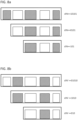
- FIG. 7 illustrates both exemplary principles. If the measurement signal is greater than or equal to the reference signal, the digital measurement signal has the value 1 (or 0) in this time interval. If the measurement signal is smaller than a threshold voltage U 0 , the digital measurement signal has the value 0 (or 1) in this time interval.
- the threshold voltage U 0 serves as a predeterminable threshold value and is in any case less than or equal to the minimum value of the reference signal. In all other cases, no value is assigned to the digital measurement signal.
- FIG. 7 This is shown by hatched and non-hatched blocks.
- the durations of the signal intervals (width of the blocks) during which the digital measurement signal is 1 or 0, and possibly also during which no value is assigned to it (empty), can, for example, be determined again via the times t701-t706 or t711 - t714 become.
- the times t701, t703 and t705 can be determined via the times at which the digital measurement signal dIN+ changes from “0” or "empty” to "1”
- the times t702, t704 and t706 can be determined via the times at which this digital measurement signal (dIN+) changes from “1” or “empty” to “0”.
- such an identification of the direction of movement of the shutter can also be determined if the signal evaluation unit was not able to completely capture the signal, for example because the operating voltage required for the signal evaluation was only reached later.
- FIG.8a and 8b Illustrate this FIG.8a and 8b , in which it can be seen that the sequence of digits typical for a direction of movement is suitable for determining the direction of movement up to a minimum number of three digits. It can therefore be clearly determined with just three digits of the digital measurement signal whether there was a forward or backward movement. Depending on when the signal was detected, a rewind leads to the sequences 10101, 0101 and 101 and a forward to the sequences 01010, 1010 and 010. For example, the voltage generation for the Signal evaluation unit or it starts up too slowly for whatever reason, then even if the start of the signal has not been registered to determine the direction of movement, a certain characteristic minimum section of the signal is sufficient to determine the direction of movement. By determining these at least three final digits as a direction-specific signal, incorrect or non-reports of signal detections are avoided.
- the signal evaluation unit determines whether a shot was fired in single or continuous fire. It is also possible to determine the different cadences/fire rates in individual fire. For this purpose, for example, predetermined time limit values, which are based, for example, on measured values determined in the laboratory, can define time intervals/time limit value intervals. The interval within which the determined duration lies then determines whether there is continuous fire or single fire and/or also the firing rate. The following examples illustrate this approach.
- Example 1 a time limit, automatic weapon. If the duration is above the limit (time interval 1), single fire is assumed; If it is below the limit value (time interval 2), continuous fire.
- Example 2 a time limit, semi-automatic weapon. If the duration is above the limit (time interval 1), slow single fire is assumed; If it is below the limit (time interval 1), rapid single fire.
- Example 3 two limits, automatic weapon. If the duration is above the second, larger limit (time interval 1), slow single fire is assumed. If it is between the first and second limit values (time interval 2), rapid single fire is assumed. If it is below the limit value (time interval 3), continuous fire is assumed.
- a voltage limit and measured voltage values can also be used.
- the end of the measurement signal which is generated when a first shot is advanced, can be determined as the first time and the beginning of the measurement signal, which is generated during the return of a second, following shot, as the second time. From the time between the first and second points in time, the time interval between individual shots can be deduced and from this the fire mode and, if necessary, the rate of fire.
- the time determination unit described above comprising a clock source and a timer, determines the duration between the first and second points in time.
- the time determination unit already described above comprising a capacitor and a resistor, is integrated after rectifying the signal to determine single-fire or continuous-fire sequences.
- the capacitor charges when a shot is fired and then discharges continuously via the resistor.
- the firing of single fire long sequences or pauses lead to a lower charge level
- continuous fire very short sequences lead to a higher charge level
- the degree of discharge can be converted into a time value.
- the detour via a time value determination does not have to be taken and the voltage values present on the capacitor can be used directly.
- a further exemplary embodiment differentiates between single or continuous firing sequences using the following devices and methods: If the alternatively polarized magnets sweep over the stationary coil, the induced voltage supplies the signal evaluation unit, for example consisting of a microcontroller, and the upstream capacitors with energy. If there is sufficient operating voltage, the signal evaluation unit is ready for operation and is in an active mode. In this mode, it evaluates the AC voltage signal as described, activates an internal or external clock source and a timer and configures an interrupt-capable pin, e.g. of a microcontroller.
- the signal evaluation unit for example consisting of a microcontroller
- the signal evaluation unit is then put into a low-power mode in which it only requires a fraction of the current and can therefore remain active for a relatively long time during the shutter cycle.
- the signal evaluation unit is supplied with electrical energy exclusively from pre-charged backup capacitors.
- the synchronization circuit can, for example, apply a voltage to the interrupt-capable pin, whereupon this generates an interrupt in the signal evaluation unit and the signal evaluation unit switches back from low power to active mode.
- the timer While the signal evaluation unit is in low-power mode, the timer counts the clocks of the clock source. Since the clock frequency of the clock source is known, the signal evaluation unit can convert the number of clocks called by the timer into a time value. This happens as soon as it is again supplied with operating voltage by a shot signal and has switched to active mode so that it can use the counted cycles of the timer. In this way, the signal evaluation unit determines the time between two active phases and can thus determine the different firing sequences.
- This low-power circuit is that the signal evaluation unit remains permanently activated during shutter rewind and forward movement and this activation is not interrupted and has to be restarted.
- the time between two shot signals is so far apart that the charge on the backup capacitors is not sufficient to permanently supply the signal evaluation unit.
- the operating voltage would be below the minimum voltage required for proper operation and the signal evaluation unit is deactivated.
- the signal evaluation unit is started with a hardware reset.
- the difference as to whether the change to active mode occurs from a low-power mode or from the off state is recognized using an internal register of the signal evaluation unit.
- Another embodiment uses these two scenarios to distinguish between continuous and single fire.
- the signal evaluation unit can remain active in low-power mode even during the shutter advance and until the next shot is fired and is constantly ready.
- This permanent activation over several firing cycles then serves as a distinguishing feature between continuous fire and single fire, since in the latter the activation will usually be interrupted.
- the times that go beyond one shot cycle can also be measured.
- the result of this solution is a time (cycle).
- a slow rate of fire in individual fire can be concluded.
- the shot analysis system described is peripherally equipped with a battery and an additional clock to integrate a time stamp.
- a battery exclusively for time measurement, batteries with only very small capacities and small external dimensions are required, which also ensure a reliable power supply for this real-time measurement even after years or even decades. If such a battery fails, all other described functions of the shot analysis system are still guaranteed.
Landscapes
- Engineering & Computer Science (AREA)
- General Engineering & Computer Science (AREA)
- Physics & Mathematics (AREA)
- General Physics & Mathematics (AREA)
- Power Engineering (AREA)
- Aiming, Guidance, Guns With A Light Source, Armor, Camouflage, And Targets (AREA)
- Measurement Of Unknown Time Intervals (AREA)
- Measurement Of Length, Angles, Or The Like Using Electric Or Magnetic Means (AREA)
- Devices For Checking Fares Or Tickets At Control Points (AREA)
- Analysing Materials By The Use Of Radiation (AREA)
Priority Applications (3)
| Application Number | Priority Date | Filing Date | Title |
|---|---|---|---|
| HRP20260202TT HRP20260202T1 (hr) | 2021-02-25 | 2022-02-25 | Uređaj za analizu vatrenog oružja |
| EP25221922.5A EP4707717A2 (fr) | 2021-02-25 | 2022-02-25 | Dispositif d'analyse d'arme à feu |
| RS20260223A RS67819B1 (sr) | 2021-02-25 | 2022-02-25 | Uređaj za analizu vatrenog oružja |
Applications Claiming Priority (2)
| Application Number | Priority Date | Filing Date | Title |
|---|---|---|---|
| DE102021104517.7A DE102021104517B4 (de) | 2021-02-25 | 2021-02-25 | Schusswaffenanalysevorrichtung |
| EP22158688.6A EP4050297B1 (fr) | 2021-02-25 | 2022-02-25 | Dispositif d'analyse d'arme à feu |
Related Parent Applications (2)
| Application Number | Title | Priority Date | Filing Date |
|---|---|---|---|
| EP22158688.6A Division EP4050297B1 (fr) | 2021-02-25 | 2022-02-25 | Dispositif d'analyse d'arme à feu |
| EP22158688.6A Division-Into EP4050297B1 (fr) | 2021-02-25 | 2022-02-25 | Dispositif d'analyse d'arme à feu |
Related Child Applications (1)
| Application Number | Title | Priority Date | Filing Date |
|---|---|---|---|
| EP25221922.5A Division EP4707717A2 (fr) | 2021-02-25 | 2022-02-25 | Dispositif d'analyse d'arme à feu |
Publications (4)
| Publication Number | Publication Date |
|---|---|
| EP4328536A2 true EP4328536A2 (fr) | 2024-02-28 |
| EP4328536A3 EP4328536A3 (fr) | 2024-04-17 |
| EP4328536B1 EP4328536B1 (fr) | 2025-12-31 |
| EP4328536C0 EP4328536C0 (fr) | 2025-12-31 |
Family
ID=80461442
Family Applications (3)
| Application Number | Title | Priority Date | Filing Date |
|---|---|---|---|
| EP24151898.4A Active EP4328536B1 (fr) | 2021-02-25 | 2022-02-25 | Dispositif d'analyse d'arme à feu |
| EP25221922.5A Pending EP4707717A2 (fr) | 2021-02-25 | 2022-02-25 | Dispositif d'analyse d'arme à feu |
| EP22158688.6A Active EP4050297B1 (fr) | 2021-02-25 | 2022-02-25 | Dispositif d'analyse d'arme à feu |
Family Applications After (2)
| Application Number | Title | Priority Date | Filing Date |
|---|---|---|---|
| EP25221922.5A Pending EP4707717A2 (fr) | 2021-02-25 | 2022-02-25 | Dispositif d'analyse d'arme à feu |
| EP22158688.6A Active EP4050297B1 (fr) | 2021-02-25 | 2022-02-25 | Dispositif d'analyse d'arme à feu |
Country Status (11)
| Country | Link |
|---|---|
| US (1) | US11802747B2 (fr) |
| EP (3) | EP4328536B1 (fr) |
| JP (1) | JP7845879B2 (fr) |
| KR (1) | KR20220121732A (fr) |
| CA (1) | CA3150174A1 (fr) |
| DE (1) | DE102021104517B4 (fr) |
| ES (2) | ES3063906T3 (fr) |
| HR (2) | HRP20240460T1 (fr) |
| HU (1) | HUE067129T2 (fr) |
| PL (2) | PL4328536T3 (fr) |
| RS (2) | RS67819B1 (fr) |
Families Citing this family (6)
| Publication number | Priority date | Publication date | Assignee | Title |
|---|---|---|---|---|
| US12487044B2 (en) | 2017-01-27 | 2025-12-02 | Armaments Research Company, Inc. | Weapon usage monitoring system having discharge event monitoring directed toward quick change barrel |
| US20240068761A1 (en) | 2017-01-27 | 2024-02-29 | Armaments Research Company, Inc. | Weapon usage monitoring system having predictive maintenance and performance metrics |
| US12442607B2 (en) | 2017-01-27 | 2025-10-14 | Armaments Research Company, Inc. | Weapon usage monitoring system having discharge event monitoring based on multiple sensor authentication |
| US11719497B2 (en) | 2018-10-22 | 2023-08-08 | Magpul Industries Corp. | Determination of round count by hall switch encoding |
| EP4438992B1 (fr) * | 2023-03-30 | 2025-12-31 | Armaments Research Company Inc. | Système de surveillance d'utilisation d'arme ayant une surveillance d'événement de décharge sur la base de la vitesse de déplacement |
| DE102024110193A1 (de) * | 2024-04-11 | 2025-10-16 | FINE Intelligent Engineering GmbH | Schussauswertevorrichtung und Feuerwaffe |
Citations (2)
| Publication number | Priority date | Publication date | Assignee | Title |
|---|---|---|---|---|
| US8046946B2 (en) | 2006-08-11 | 2011-11-01 | Packer Engineering, Inc. | Shot-counting device for a firearm |
| EP3140605B1 (fr) | 2015-06-29 | 2019-05-01 | Heckler & Koch GmbH | Compteur de coups |
Family Cites Families (17)
| Publication number | Priority date | Publication date | Assignee | Title |
|---|---|---|---|---|
| DE4203585C2 (de) | 1992-02-07 | 1996-04-25 | Heckler & Koch Gmbh | Vorrichtung zum Ermitteln des Verschleißzustandes einer Schußwaffe |
| US7509766B2 (en) * | 2003-02-07 | 2009-03-31 | Eduardo Carlos Vasquez | Weapon use tracking and signaling system |
| US8290747B2 (en) | 2005-10-21 | 2012-10-16 | Microstrain, Inc. | Structural damage detection and analysis system |
| US7747415B1 (en) * | 2005-12-22 | 2010-06-29 | Microstrain, Inc. | Sensor powered event logger |
| BE1017549A3 (fr) | 2006-07-18 | 2008-12-02 | Fn Herstal Sa | Dispositif pour la detection et le comptage des coups tires par une arme automatique ou semi-automatique et arme equipee d'un tel dispositif. |
| JP2008064406A (ja) | 2006-09-08 | 2008-03-21 | Hitachi Kokusai Electric Inc | 弾数計測装置 |
| DE102007062646B4 (de) * | 2007-12-24 | 2011-05-19 | Carl Walther Gmbh | Vorrichtung zur Erzeugung elektrischer Energie in Schusswaffen |
| ITMI20081178A1 (it) * | 2008-06-27 | 2009-12-28 | Beretta Armi Spa | Apparato contacolpi per armi da fuoco leggere |
| US8432305B2 (en) * | 2009-09-03 | 2013-04-30 | Samsung Electronics Co., Ltd. | Electronic apparatus, control method thereof, remote control apparatus, and control method thereof |
| EP2642237A1 (fr) | 2010-11-18 | 2013-09-25 | Raul Delgado Acarreta | Compteur électronique |
| JP5924199B2 (ja) * | 2012-09-05 | 2016-05-25 | ソニー株式会社 | 電源監視装置、交直変換装置、および、電源監視装置の制御方法 |
| IL230906A (en) | 2014-02-10 | 2016-07-31 | Israel Weapon Ind (I W I ) Ltd | A device and method for counting projectiles fired from weapons |
| US10211736B2 (en) * | 2017-01-23 | 2019-02-19 | Lg Chem, Ltd. | Power supply system and detection system for determining an unbalanced current condition and an overcurrent condition in a DC-DC voltage converter |
| BE1025010B1 (fr) | 2017-02-28 | 2018-09-25 | Fn Herstal Sa | Dispositif de mesure de regime de tirs et de cadence d'une arme |
| US10900732B2 (en) * | 2017-03-08 | 2021-01-26 | Sturm, Ruger & Company, Inc. | Electromagnetic firing system for firearm with firing event tracking |
| DE102017127070A1 (de) * | 2017-11-17 | 2019-05-23 | Eaton Electrical Ip Gmbh & Co. Kg | Schaltungsanordnung und Verfahren zur Überwachung wechselspannungsförmiger Signale |
| GB201906204D0 (en) * | 2019-05-02 | 2019-06-19 | Nordic Semiconductor Asa | Voltage monitoring |
-
2021
- 2021-02-25 DE DE102021104517.7A patent/DE102021104517B4/de active Active
-
2022
- 2022-02-24 KR KR1020220024189A patent/KR20220121732A/ko active Pending
- 2022-02-25 EP EP24151898.4A patent/EP4328536B1/fr active Active
- 2022-02-25 ES ES24151898T patent/ES3063906T3/es active Active
- 2022-02-25 RS RS20260223A patent/RS67819B1/sr unknown
- 2022-02-25 ES ES22158688T patent/ES2976297T3/es active Active
- 2022-02-25 HU HUE22158688A patent/HUE067129T2/hu unknown
- 2022-02-25 EP EP25221922.5A patent/EP4707717A2/fr active Pending
- 2022-02-25 CA CA3150174A patent/CA3150174A1/fr active Pending
- 2022-02-25 PL PL24151898.4T patent/PL4328536T3/pl unknown
- 2022-02-25 PL PL22158688.6T patent/PL4050297T3/pl unknown
- 2022-02-25 US US17/681,302 patent/US11802747B2/en active Active
- 2022-02-25 RS RS20240530A patent/RS65505B1/sr unknown
- 2022-02-25 HR HRP20240460TT patent/HRP20240460T1/hr unknown
- 2022-02-25 HR HRP20260202TT patent/HRP20260202T1/hr unknown
- 2022-02-25 EP EP22158688.6A patent/EP4050297B1/fr active Active
- 2022-02-25 JP JP2022027511A patent/JP7845879B2/ja active Active
Patent Citations (2)
| Publication number | Priority date | Publication date | Assignee | Title |
|---|---|---|---|---|
| US8046946B2 (en) | 2006-08-11 | 2011-11-01 | Packer Engineering, Inc. | Shot-counting device for a firearm |
| EP3140605B1 (fr) | 2015-06-29 | 2019-05-01 | Heckler & Koch GmbH | Compteur de coups |
Also Published As
| Publication number | Publication date |
|---|---|
| ES2976297T3 (es) | 2024-07-29 |
| CA3150174A1 (fr) | 2022-08-25 |
| EP4050297A1 (fr) | 2022-08-31 |
| JP7845879B2 (ja) | 2026-04-14 |
| DE102021104517A1 (de) | 2022-08-25 |
| HUE067129T2 (hu) | 2024-10-28 |
| HRP20260202T1 (hr) | 2026-03-27 |
| US11802747B2 (en) | 2023-10-31 |
| EP4328536A3 (fr) | 2024-04-17 |
| JP2022130350A (ja) | 2022-09-06 |
| US20220412684A1 (en) | 2022-12-29 |
| HRP20240460T1 (hr) | 2024-07-05 |
| EP4707717A2 (fr) | 2026-03-11 |
| RS65505B1 (sr) | 2024-06-28 |
| EP4328536B1 (fr) | 2025-12-31 |
| KR20220121732A (ko) | 2022-09-01 |
| RS67819B1 (sr) | 2026-03-31 |
| PL4328536T3 (pl) | 2026-03-30 |
| ES3063906T3 (en) | 2026-04-21 |
| DE102021104517B4 (de) | 2023-09-28 |
| EP4050297B1 (fr) | 2024-02-21 |
| EP4328536C0 (fr) | 2025-12-31 |
| PL4050297T3 (pl) | 2024-06-10 |
| EP4050297C0 (fr) | 2024-02-21 |
Similar Documents
| Publication | Publication Date | Title |
|---|---|---|
| EP4050297B1 (fr) | Dispositif d'analyse d'arme à feu | |
| EP3140605B1 (fr) | Compteur de coups | |
| DE2644646C2 (de) | Vorrichtung zur Erkennung eines oder mehrerer fehlender Impulse in einer sonst regelmäßigen Impulsfolge | |
| DE102010003526A1 (de) | Vorrichtung und Verfahren zur Verarbeitung von Signalen, die eine Winkelstellung einer Welle eines Motors repräsentieren | |
| DE2621075A1 (de) | Fruehzuendungssystem fuer brennkraftmaschinen | |
| DE2545325C3 (de) | Schaltungsanordnung zur Messung des Isolationswiderstandes erdfreier Starkstromschaltungen | |
| DE2352941C2 (de) | Verfahren und Einrichtung zur Auslösung eines Impulses innerhalb eines Verstellbereiches einer Antriebsmaschine | |
| DE102007063679A1 (de) | Vorrichtung zur Erzeugung elektrischer Signale in einer Schusswaffe | |
| DE102011018430A1 (de) | Induktiver Näherungsschalter | |
| DE3943394A1 (de) | Triggerschaltung mit selbsteinstellendem referenzwert | |
| DE3919927A1 (de) | Verfahren zur erkennung einer vorbestimmten zeigerstellung und anzeigeeinrichtung | |
| DE102012102308B4 (de) | Verfahren zur Detektion von Spannungsimpulsen, Schaltungsanordnung und Positionsmessvorrichtung | |
| DE3244940C2 (fr) | ||
| DE3533529C2 (fr) | ||
| DE68907975T2 (de) | Elektronische Versorgung für eine Ionenpumpe. | |
| DE2321517C3 (de) | Analog-Digitalwandler | |
| DE102013017008B4 (de) | Drehrichtungserkennung einer Zündvorrichtung | |
| EP0916180B1 (fr) | Procede de reconnaissance sans capteur du pas dans des moteurs pas a pas | |
| DE2239449A1 (de) | Verfahren und einrichtung zur erzeugung einer groesse, die der mittleren impulshoehe einer vielzahl von eingangsimpulsen proportional ist | |
| DE3427582C2 (de) | Verfahren zum Auslösen von Wiegand-Impulsen | |
| EP0050676B2 (fr) | Procédé et dispositif pour maintenir la symétrie d'entrée d'un convertisseur push-pull lors de grandes variations de la tension d'entrée | |
| DE2744073A1 (de) | Kondensator-zuendsystem | |
| DE1933358C3 (de) | Einrichtung zur Bestimmung einer Bewegungsgröße eines für ein Uhrwerk vorgesehenen Unruh-Schwingsystem | |
| DE1949930C3 (de) | SchuOfadenwächter | |
| DE1203480B (de) | Vorrichtung zur fortlaufenden Differenzzaehlung zweier nichtsynchroner Impulsreihen |
Legal Events
| Date | Code | Title | Description |
|---|---|---|---|
| REG | Reference to a national code |
Ref country code: HR Ref legal event code: TUEP Ref document number: P20260202T Country of ref document: HR |
|
| PUAI | Public reference made under article 153(3) epc to a published international application that has entered the european phase |
Free format text: ORIGINAL CODE: 0009012 |
|
| STAA | Information on the status of an ep patent application or granted ep patent |
Free format text: STATUS: THE APPLICATION HAS BEEN PUBLISHED |
|
| AC | Divisional application: reference to earlier application |
Ref document number: 4050297 Country of ref document: EP Kind code of ref document: P |
|
| AK | Designated contracting states |
Kind code of ref document: A2 Designated state(s): AL AT BE BG CH CY CZ DE DK EE ES FI FR GB GR HR HU IE IS IT LI LT LU LV MC MK MT NL NO PL PT RO RS SE SI SK SM TR |
|
| PUAL | Search report despatched |
Free format text: ORIGINAL CODE: 0009013 |
|
| AK | Designated contracting states |
Kind code of ref document: A3 Designated state(s): AL AT BE BG CH CY CZ DE DK EE ES FI FR GB GR HR HU IE IS IT LI LT LU LV MC MK MT NL NO PL PT RO RS SE SI SK SM TR |
|
| RIC1 | Information provided on ipc code assigned before grant |
Ipc: F41A 19/01 20060101AFI20240311BHEP |
|
| STAA | Information on the status of an ep patent application or granted ep patent |
Free format text: STATUS: REQUEST FOR EXAMINATION WAS MADE |
|
| 17P | Request for examination filed |
Effective date: 20241009 |
|
| RBV | Designated contracting states (corrected) |
Designated state(s): AL AT BE BG CH CY CZ DE DK EE ES FI FR GB GR HR HU IE IS IT LI LT LU LV MC MK MT NL NO PL PT RO RS SE SI SK SM TR |
|
| GRAP | Despatch of communication of intention to grant a patent |
Free format text: ORIGINAL CODE: EPIDOSNIGR1 |
|
| STAA | Information on the status of an ep patent application or granted ep patent |
Free format text: STATUS: GRANT OF PATENT IS INTENDED |
|
| INTG | Intention to grant announced |
Effective date: 20250310 |
|
| GRAJ | Information related to disapproval of communication of intention to grant by the applicant or resumption of examination proceedings by the epo deleted |
Free format text: ORIGINAL CODE: EPIDOSDIGR1 |
|
| STAA | Information on the status of an ep patent application or granted ep patent |
Free format text: STATUS: REQUEST FOR EXAMINATION WAS MADE |
|
| GRAS | Grant fee paid |
Free format text: ORIGINAL CODE: EPIDOSNIGR3 |
|
| STAA | Information on the status of an ep patent application or granted ep patent |
Free format text: STATUS: GRANT OF PATENT IS INTENDED |
|
| GRAP | Despatch of communication of intention to grant a patent |
Free format text: ORIGINAL CODE: EPIDOSNIGR1 |
|
| INTC | Intention to grant announced (deleted) | ||
| INTG | Intention to grant announced |
Effective date: 20250723 |
|
| GRAA | (expected) grant |
Free format text: ORIGINAL CODE: 0009210 |
|
| STAA | Information on the status of an ep patent application or granted ep patent |
Free format text: STATUS: THE PATENT HAS BEEN GRANTED |
|
| AC | Divisional application: reference to earlier application |
Ref document number: 4050297 Country of ref document: EP Kind code of ref document: P |
|
| AK | Designated contracting states |
Kind code of ref document: B1 Designated state(s): AL AT BE BG CH CY CZ DE DK EE ES FI FR GB GR HR HU IE IS IT LI LT LU LV MC MK MT NL NO PL PT RO RS SE SI SK SM TR |
|
| REG | Reference to a national code |
Ref country code: CH Ref legal event code: F10 Free format text: ST27 STATUS EVENT CODE: U-0-0-F10-F00 (AS PROVIDED BY THE NATIONAL OFFICE) Effective date: 20251231 Ref country code: GB Ref legal event code: FG4D Free format text: NOT ENGLISH |
|
| REG | Reference to a national code |
Ref country code: DE Ref legal event code: R096 Ref document number: 502022006681 Country of ref document: DE |
|
| REG | Reference to a national code |
Ref country code: CH Ref legal event code: R17 Free format text: ST27 STATUS EVENT CODE: U-0-0-R10-R17 (AS PROVIDED BY THE NATIONAL OFFICE) Effective date: 20260122 |
|
| REG | Reference to a national code |
Ref country code: IE Ref legal event code: FG4D Free format text: LANGUAGE OF EP DOCUMENT: GERMAN |
|
| U01 | Request for unitary effect filed |
Effective date: 20260122 |
|
| U07 | Unitary effect registered |
Designated state(s): AT BE BG DE DK EE FI FR IT LT LU LV MT NL PT RO SE SI Effective date: 20260128 |
|
| REG | Reference to a national code |
Ref country code: HR Ref legal event code: ODRP Ref document number: P20260202T Country of ref document: HR Payment date: 20260219 Year of fee payment: 5 |
|
| REG | Reference to a national code |
Ref country code: SK Ref legal event code: T3 Ref document number: E 47951 Country of ref document: SK |
|
| REG | Reference to a national code |
Ref country code: CH Ref legal event code: U11 Free format text: ST27 STATUS EVENT CODE: U-0-0-U10-U11 (AS PROVIDED BY THE NATIONAL OFFICE) Effective date: 20260326 |
|
| REG | Reference to a national code |
Ref country code: HR Ref legal event code: T1PR Ref document number: P20260202 Country of ref document: HR |
|
| PGFP | Annual fee paid to national office [announced via postgrant information from national office to epo] |
Ref country code: GB Payment date: 20260219 Year of fee payment: 5 |
|
| PGFP | Annual fee paid to national office [announced via postgrant information from national office to epo] |
Ref country code: ES Payment date: 20260319 Year of fee payment: 5 |
|
| PGFP | Annual fee paid to national office [announced via postgrant information from national office to epo] |
Ref country code: NO Payment date: 20260320 Year of fee payment: 5 |
|
| PGFP | Annual fee paid to national office [announced via postgrant information from national office to epo] |
Ref country code: HR Payment date: 20260219 Year of fee payment: 5 Ref country code: AT Payment date: 20260301 Year of fee payment: 5 |
|
| PGFP | Annual fee paid to national office [announced via postgrant information from national office to epo] |
Ref country code: RS Payment date: 20260219 Year of fee payment: 5 |
|
| PGFP | Annual fee paid to national office [announced via postgrant information from national office to epo] |
Ref country code: TR Payment date: 20260319 Year of fee payment: 5 |
|
| REG | Reference to a national code |
Ref country code: ES Ref legal event code: FG2A Ref document number: 3063906 Country of ref document: ES Kind code of ref document: T3 Effective date: 20260421 |
|
| PGFP | Annual fee paid to national office [announced via postgrant information from national office to epo] |
Ref country code: CH Payment date: 20260326 Year of fee payment: 5 Ref country code: CZ Payment date: 20260217 Year of fee payment: 5 |
|
| PGFP | Annual fee paid to national office [announced via postgrant information from national office to epo] |
Ref country code: PL Payment date: 20260218 Year of fee payment: 5 |
|
| PGFP | Annual fee paid to national office [announced via postgrant information from national office to epo] |
Ref country code: SK Payment date: 20260219 Year of fee payment: 5 |
|
| U20 | Renewal fee for the european patent with unitary effect paid |
Year of fee payment: 5 Effective date: 20260319 |