EP4328544A1 - Analyseverfahren, analysevorrichtung, messverfahren, messvorrichtung, belichtungsverfahren und belichtungsvorrichtung - Google Patents
Analyseverfahren, analysevorrichtung, messverfahren, messvorrichtung, belichtungsverfahren und belichtungsvorrichtung Download PDFInfo
- Publication number
- EP4328544A1 EP4328544A1 EP22791619.4A EP22791619A EP4328544A1 EP 4328544 A1 EP4328544 A1 EP 4328544A1 EP 22791619 A EP22791619 A EP 22791619A EP 4328544 A1 EP4328544 A1 EP 4328544A1
- Authority
- EP
- European Patent Office
- Prior art keywords
- measured
- substrate
- function
- position information
- proportional coefficient
- Prior art date
- Legal status (The legal status is an assumption and is not a legal conclusion. Google has not performed a legal analysis and makes no representation as to the accuracy of the status listed.)
- Pending
Links
Images


Classifications
-
- G—PHYSICS
- G03—PHOTOGRAPHY; CINEMATOGRAPHY; ANALOGOUS TECHNIQUES USING WAVES OTHER THAN OPTICAL WAVES; ELECTROGRAPHY; HOLOGRAPHY
- G03F—PHOTOMECHANICAL PRODUCTION OF TEXTURED OR PATTERNED SURFACES, e.g. FOR PRINTING, FOR PROCESSING OF SEMICONDUCTOR DEVICES; MATERIALS THEREFOR; ORIGINALS THEREFOR; APPARATUS SPECIALLY ADAPTED THEREFOR
- G03F7/00—Photomechanical, e.g. photolithographic, production of textured or patterned surfaces, e.g. printing surfaces; Materials therefor, e.g. comprising photoresists; Apparatus specially adapted therefor
- G03F7/70—Microphotolithographic exposure; Apparatus therefor
- G03F7/70691—Handling of masks or workpieces
- G03F7/70783—Handling stress or warp of chucks, masks or workpieces, e.g. to compensate for imaging errors or considerations related to warpage of masks or workpieces due to their own weight
-
- G—PHYSICS
- G03—PHOTOGRAPHY; CINEMATOGRAPHY; ANALOGOUS TECHNIQUES USING WAVES OTHER THAN OPTICAL WAVES; ELECTROGRAPHY; HOLOGRAPHY
- G03F—PHOTOMECHANICAL PRODUCTION OF TEXTURED OR PATTERNED SURFACES, e.g. FOR PRINTING, FOR PROCESSING OF SEMICONDUCTOR DEVICES; MATERIALS THEREFOR; ORIGINALS THEREFOR; APPARATUS SPECIALLY ADAPTED THEREFOR
- G03F9/00—Registration or positioning of originals, masks, frames, photographic sheets or textured or patterned surfaces, e.g. automatically
- G03F9/70—Registration or positioning of originals, masks, frames, photographic sheets or textured or patterned surfaces, e.g. automatically for microlithography
- G03F9/7088—Alignment mark detection, e.g. TTR, TTL, off-axis detection, array detector, video detection
-
- G—PHYSICS
- G01—MEASURING; TESTING
- G01B—MEASURING LENGTH, THICKNESS OR SIMILAR LINEAR DIMENSIONS; MEASURING ANGLES; MEASURING AREAS; MEASURING IRREGULARITIES OF SURFACES OR CONTOURS
- G01B21/00—Measuring arrangements or details thereof, where the measuring technique is not covered by the other groups of this subclass, unspecified or not relevant
- G01B21/32—Measuring arrangements or details thereof, where the measuring technique is not covered by the other groups of this subclass, unspecified or not relevant for measuring the deformation in a solid
-
- G—PHYSICS
- G01—MEASURING; TESTING
- G01B—MEASURING LENGTH, THICKNESS OR SIMILAR LINEAR DIMENSIONS; MEASURING ANGLES; MEASURING AREAS; MEASURING IRREGULARITIES OF SURFACES OR CONTOURS
- G01B21/00—Measuring arrangements or details thereof, where the measuring technique is not covered by the other groups of this subclass, unspecified or not relevant
- G01B21/02—Measuring arrangements or details thereof, where the measuring technique is not covered by the other groups of this subclass, unspecified or not relevant for measuring length, width, or thickness
- G01B21/04—Measuring arrangements or details thereof, where the measuring technique is not covered by the other groups of this subclass, unspecified or not relevant for measuring length, width, or thickness by measuring coordinates of points
-
- G—PHYSICS
- G03—PHOTOGRAPHY; CINEMATOGRAPHY; ANALOGOUS TECHNIQUES USING WAVES OTHER THAN OPTICAL WAVES; ELECTROGRAPHY; HOLOGRAPHY
- G03F—PHOTOMECHANICAL PRODUCTION OF TEXTURED OR PATTERNED SURFACES, e.g. FOR PRINTING, FOR PROCESSING OF SEMICONDUCTOR DEVICES; MATERIALS THEREFOR; ORIGINALS THEREFOR; APPARATUS SPECIALLY ADAPTED THEREFOR
- G03F7/00—Photomechanical, e.g. photolithographic, production of textured or patterned surfaces, e.g. printing surfaces; Materials therefor, e.g. comprising photoresists; Apparatus specially adapted therefor
- G03F7/20—Exposure; Apparatus therefor
-
- G—PHYSICS
- G03—PHOTOGRAPHY; CINEMATOGRAPHY; ANALOGOUS TECHNIQUES USING WAVES OTHER THAN OPTICAL WAVES; ELECTROGRAPHY; HOLOGRAPHY
- G03F—PHOTOMECHANICAL PRODUCTION OF TEXTURED OR PATTERNED SURFACES, e.g. FOR PRINTING, FOR PROCESSING OF SEMICONDUCTOR DEVICES; MATERIALS THEREFOR; ORIGINALS THEREFOR; APPARATUS SPECIALLY ADAPTED THEREFOR
- G03F7/00—Photomechanical, e.g. photolithographic, production of textured or patterned surfaces, e.g. printing surfaces; Materials therefor, e.g. comprising photoresists; Apparatus specially adapted therefor
- G03F7/70—Microphotolithographic exposure; Apparatus therefor
- G03F7/70216—Mask projection systems
- G03F7/70341—Details of immersion lithography aspects, e.g. exposure media or control of immersion liquid supply
-
- G—PHYSICS
- G03—PHOTOGRAPHY; CINEMATOGRAPHY; ANALOGOUS TECHNIQUES USING WAVES OTHER THAN OPTICAL WAVES; ELECTROGRAPHY; HOLOGRAPHY
- G03F—PHOTOMECHANICAL PRODUCTION OF TEXTURED OR PATTERNED SURFACES, e.g. FOR PRINTING, FOR PROCESSING OF SEMICONDUCTOR DEVICES; MATERIALS THEREFOR; ORIGINALS THEREFOR; APPARATUS SPECIALLY ADAPTED THEREFOR
- G03F7/00—Photomechanical, e.g. photolithographic, production of textured or patterned surfaces, e.g. printing surfaces; Materials therefor, e.g. comprising photoresists; Apparatus specially adapted therefor
- G03F7/70—Microphotolithographic exposure; Apparatus therefor
- G03F7/70691—Handling of masks or workpieces
- G03F7/707—Chucks, e.g. chucking or un-chucking operations or structural details
-
- G—PHYSICS
- G03—PHOTOGRAPHY; CINEMATOGRAPHY; ANALOGOUS TECHNIQUES USING WAVES OTHER THAN OPTICAL WAVES; ELECTROGRAPHY; HOLOGRAPHY
- G03F—PHOTOMECHANICAL PRODUCTION OF TEXTURED OR PATTERNED SURFACES, e.g. FOR PRINTING, FOR PROCESSING OF SEMICONDUCTOR DEVICES; MATERIALS THEREFOR; ORIGINALS THEREFOR; APPARATUS SPECIALLY ADAPTED THEREFOR
- G03F7/00—Photomechanical, e.g. photolithographic, production of textured or patterned surfaces, e.g. printing surfaces; Materials therefor, e.g. comprising photoresists; Apparatus specially adapted therefor
- G03F7/70—Microphotolithographic exposure; Apparatus therefor
- G03F7/70691—Handling of masks or workpieces
- G03F7/70716—Stages
- G03F7/70725—Stages control
-
- G—PHYSICS
- G03—PHOTOGRAPHY; CINEMATOGRAPHY; ANALOGOUS TECHNIQUES USING WAVES OTHER THAN OPTICAL WAVES; ELECTROGRAPHY; HOLOGRAPHY
- G03F—PHOTOMECHANICAL PRODUCTION OF TEXTURED OR PATTERNED SURFACES, e.g. FOR PRINTING, FOR PROCESSING OF SEMICONDUCTOR DEVICES; MATERIALS THEREFOR; ORIGINALS THEREFOR; APPARATUS SPECIALLY ADAPTED THEREFOR
- G03F7/00—Photomechanical, e.g. photolithographic, production of textured or patterned surfaces, e.g. printing surfaces; Materials therefor, e.g. comprising photoresists; Apparatus specially adapted therefor
- G03F7/70—Microphotolithographic exposure; Apparatus therefor
- G03F7/70691—Handling of masks or workpieces
- G03F7/70733—Handling masks and workpieces, e.g. exchange of workpiece or mask, transport of workpiece or mask
-
- G—PHYSICS
- G03—PHOTOGRAPHY; CINEMATOGRAPHY; ANALOGOUS TECHNIQUES USING WAVES OTHER THAN OPTICAL WAVES; ELECTROGRAPHY; HOLOGRAPHY
- G03F—PHOTOMECHANICAL PRODUCTION OF TEXTURED OR PATTERNED SURFACES, e.g. FOR PRINTING, FOR PROCESSING OF SEMICONDUCTOR DEVICES; MATERIALS THEREFOR; ORIGINALS THEREFOR; APPARATUS SPECIALLY ADAPTED THEREFOR
- G03F7/00—Photomechanical, e.g. photolithographic, production of textured or patterned surfaces, e.g. printing surfaces; Materials therefor, e.g. comprising photoresists; Apparatus specially adapted therefor
- G03F7/70—Microphotolithographic exposure; Apparatus therefor
- G03F7/70691—Handling of masks or workpieces
- G03F7/70775—Position control, e.g. interferometers or encoders for determining the stage position
-
- G—PHYSICS
- G03—PHOTOGRAPHY; CINEMATOGRAPHY; ANALOGOUS TECHNIQUES USING WAVES OTHER THAN OPTICAL WAVES; ELECTROGRAPHY; HOLOGRAPHY
- G03F—PHOTOMECHANICAL PRODUCTION OF TEXTURED OR PATTERNED SURFACES, e.g. FOR PRINTING, FOR PROCESSING OF SEMICONDUCTOR DEVICES; MATERIALS THEREFOR; ORIGINALS THEREFOR; APPARATUS SPECIALLY ADAPTED THEREFOR
- G03F7/00—Photomechanical, e.g. photolithographic, production of textured or patterned surfaces, e.g. printing surfaces; Materials therefor, e.g. comprising photoresists; Apparatus specially adapted therefor
- G03F7/70—Microphotolithographic exposure; Apparatus therefor
- G03F7/708—Construction of apparatus, e.g. environment aspects, hygiene aspects or materials
- G03F7/7085—Detection arrangement, e.g. detectors of apparatus alignment possibly mounted on wafers, exposure dose, photo-cleaning flux, stray light, thermal load
-
- G—PHYSICS
- G03—PHOTOGRAPHY; CINEMATOGRAPHY; ANALOGOUS TECHNIQUES USING WAVES OTHER THAN OPTICAL WAVES; ELECTROGRAPHY; HOLOGRAPHY
- G03F—PHOTOMECHANICAL PRODUCTION OF TEXTURED OR PATTERNED SURFACES, e.g. FOR PRINTING, FOR PROCESSING OF SEMICONDUCTOR DEVICES; MATERIALS THEREFOR; ORIGINALS THEREFOR; APPARATUS SPECIALLY ADAPTED THEREFOR
- G03F9/00—Registration or positioning of originals, masks, frames, photographic sheets or textured or patterned surfaces, e.g. automatically
- G03F9/70—Registration or positioning of originals, masks, frames, photographic sheets or textured or patterned surfaces, e.g. automatically for microlithography
- G03F9/7003—Alignment type or strategy, e.g. leveling, global alignment
- G03F9/7046—Strategy, e.g. mark, sensor or wavelength selection
Definitions
- the present invention relates to an analyzing method, an analysis apparatus, a measuring method, a measurement apparatus, an exposing method, and an exposure apparatus.
- an analyzing method includes preparing measured position information that is position information of a plurality of measured-parts formed on a substrate; and fitting a reference function, which is a sum of at least one function obtained by multiplying a criterion function expressed using a first type Bessel function by a proportional coefficient, to the measured position information and calculating an optimum value of at least one of the proportional coefficient.
- an analysis apparatus includes an input part configured to input measured position information that is position information of a plurality of measured-parts formed on a substrate; an analysis part configured to analyze the measured position information of the measured-part that has been measured by a position measurement part; and an output part configured to output an analysis result including at least a calculated optimum value of a proportional coefficient to external equipment, the analysis part calculating an optimum value of at least one of the proportional coefficient using the analyzing method according to the first aspect.
- a measuring method includes measuring positions of a plurality of measured-parts formed on a substrate and obtaining measured position information of the measured-parts; and calculating an optimum value of at least one of the proportional coefficient using the analyzing method according to the first aspect.
- a measurement apparatus includes a position measurement part configured to measure a position of a measured-part formed on a substrate; and an analysis part configured to analyze measured position information of the measured-part that is measured by the position measurement part, the analysis part calculating an optimum value of at least one of the proportional coefficient using the analyzing method according to the first aspect.
- an exposing method includes measuring positions of the plurality of measured-parts on the substrate on which the first pattern is formed with a predetermined positional relation with respect to the measured-part using the measuring method according to the second aspect, acquiring measured position information of the measured-part and calculating an optimum value of at least one of the proportional coefficient; estimating a position of a first pattern formed on the substrate with a predetermined positional relation with respect to the plurality of measured-parts based on the acquired measured position information and the optimum value of at least one of the proportional coefficient; and exposing a second pattern on the substrate based on the estimated position of the first pattern.
- an exposure apparatus includes a position measurement part configured to measure a position of a measured-part formed on a substrate; and an exposure optical system configured to expose a desired pattern on the substrate, and performing the exposing method according to the fourth aspect.
- an exposure apparatus includes a stage configured to have placed thereon and move a substrate on which a measured-part is formed; and a substrate conveyance device configured to convey the substrate and place the substrate on the stage, and the exposure apparatus exposes a desired pattern on the substrate, a device constant that defines an operation of the substrate conveyance device is determined based on a measurement result obtained by the measuring method according to the second aspect.
- FIG. 1 is a view schematically showing a configuration of a measurement apparatus 1 and an exposure apparatus 2 of an embodiment.
- the exposure apparatus 2 includes the measurement apparatus 1 of the embodiment surrounded by a dashed line in FIG. 1 .
- the measurement apparatus 1 of the embodiment may be a part of a configuration of the exposure apparatus 2 as shown in FIG. 1 , and may be a device independent from the exposure apparatus 2.
- the measurement apparatus 1 will be described as a part of the configuration of the exposure apparatus 2.
- An X direction, a Y direction and a Z direction are perpendicular to each other and shown by arrows in FIG. 1 and the following drawings, and each of the X direction, the Y direction and the Z direction indicates the same direction in each drawing.
- a position in the X direction is referred to as an X position
- a position in the Y direction is referred to as a Y position.
- the exposure apparatus 2 is a device configured to expose and transfer a predetermined pattern to a surface of a substrate WF.
- the exposure apparatus 2 includes an exposure optical system 20 surrounded by a two-dot dashed line in FIG. 1 , a stage 30 on which the substrate WF is placed, a mask stage 24 on which a mask 25 that is an original plate of a pattern exposed on the substrate WF is placed, and the like, in addition to the measurement apparatus 1. Further, FIG. 1 shows two stages 30 in which the positional relations in the X direction are interchanged, but there may be only one stage 30.
- the exposure optical system 20 includes an illumination optical system 21 and a projection optical system 22.
- the illumination optical system 21 irradiates the mask 25 with illumination light
- the projection optical system 22 exposes the substrate WF with exposure light that passes through the mask 25 and is given a light and shade pattern.
- the mask 25 is not limited to a transmissive mask and may be a reflective mask.
- the stage 30 includes a drive mechanism such as a linear motor or the like, and can move on a guide 33 in the X direction and the Y direction and move by a micro distance (for example, about several millimeters) in the Z direction.
- a position of the stage 30 is measured as a position of an encoder plate 32 provided on the stage 30 by an encoder head 23 provided to hold a predetermined positional relation with respect to the projection optical system 22, and output as a signal S2a.
- the mask stage 24 includes a drive mechanism such as a linear motor or the like, and can move on a mask guide 27 in the Y direction and move by a micro distance (for example, about several millimeters) in the X direction and the Z direction.
- a position of the mask stage 24 is measured as a position of an encoder plate 26 provided on the mask stage 24 by an encoder head 28 provided to hold a predetermined positional relation with respect to the projection optical system 22, and output as a signal S4.
- the exposure apparatus 2 is, for example, a scanning type exposure apparatus configured to perform exposure to the substrate WF while relatively scanning the stage 30 on which the substrate WF is placed and the mask stage 24 on which the mask 25 is placed with respect to the projection optical system 22 in the Y direction.
- the exposure apparatus 2 may be a step-and-repeat type exposure apparatus configured to perform exposure in a state in which the stage 30 on which the substrate WF is placed and the mask stage 24 on which the mask 25 is placed are stationary with respect to the projection optical system 22.
- a measures configured to measure positions of the stage 30 and the mask stage 24 is not limited to the above-mentioned encoder system, and may use a laser interferometer or a magnetic scale.
- the stage 30 has a substrate chuck part 31 in a portion on which the substrate WF is placed.
- the substrate chuck part 31 sucks the substrate WF using a so-called vacuum chuck or electrostatic chuck.
- the substrate WF exposed by the exposure apparatus 2 includes an electronic material such as a semiconductor or the like, a conventional pattern formed by the previous exposure process is present in the vicinity of a surface thereof (a surface on the +Z side), and a photosensitive material (not shown) is formed on the surface of the substrate WF.
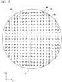
- FIG. 2A is a view showing an example of the substrate WF when the substrate WF is seen in the +Z direction.
- a plurality of predetermined measured-parts MP such as alignment marks for position measurement or the like are formed at positions having predetermined positional relations with respect to a conventional pattern on the substrate WF as a part of the conventional pattern (not shown).
- the measured-part MP is not limited to a dedicated pattern provided for measurement of a position, but may be a part of a circuit pattern that constitutes an electronic circuit formed on the substrate WF.
- An origin O shown in FIG. 2A is a center point such as a center of gravity or the like of the circular substrate WF as an example, an X axis indicates an axis extending in the X direction through the origin O, and an Y axis indicates an axis extending in the Y direction through the origin O.
- a distance from origin O to one measured-part MP is r, and a deflection angle from the +X direction to one measured-part MP with reference to the origin O is ⁇ .
- both an interval in the X direction and an interval in the Y direction between the plurality of measured-parts MP are assumed to be equal, but the interval in the X direction and the interval in the Y direction between the plurality of measured-parts MP may be unequal.
- the plurality of measured-parts MP does not necessarily need to be placed at a lattice point of a lattice arrangement parallel to the X direction and the Y direction, and may be placed at a random position on the substrate WF.
- a position of each of the measured-parts MP is already known by design data of the pattern including the measured-part MP exposed and transferred by the previous exposure process.
- the substrate WF is deformed in the XY in-plane direction by the machining process applied to the substrate WF after the exposure process through which the measured-part MP was formed, an actual accurate position of the measured-part MP is unknown.
- FIG. 2B is an enlarged view showing positions of the measured-parts MP (MP1 to MP4) in an arbitrary small region AR of the substrate WF surrounded by a broken line circle shown in FIG. 2A as an example.
- the measured-parts MP (MP1 to MP4) are disposed at positions shifted by positions expressed by DV1 to DV4 in the in-plane direction of the substrate WF due to the deformation of the substrate WF with respect to reference positions MD1 to MD4 obtained by the above-mentioned design data, respectively.
- position shift amounts of the measured-parts MP (MP1 to MP4) with respect to the reference positions MD1 to MD4, i.e., the displacement vectors DV1 to DV4 express a deformation amount of the substrate WF in the XY in-plane direction.
- the other measured-parts MP not shown in FIG. 2B are also similarly disposed at positions shifted by positions expressed by the displacement vectors DV in the in-plane direction of the substrate WF with respect to the reference positions MD1 to MD4 due to the deformation of the substrate WF, respectively.
- An X component and a Y component of the displacement vector DV are represented as ⁇ X and ⁇ Y, respectively.
- the positions at which the measured-parts MP (MP1 to MP4) are disposed actually are positions measured by a position measurement part 10, which will be described below, and hereinafter, they are referred to as measurement positions MM (MM1 to MM4) of the measured-parts MP.
- the measurement positions MM (MM1 to MM4) of the measured-parts MP (MP1 to MP4) are positions where the displacement vectors DV (DV1 to DV4) are added to reference positions MD (MD1 to MD4), respectively.
- the displacement vectors DV1 to DV4 of the measured-part MP1 to MP4 are position differences between the measurement positions MM1 to MM4 and the reference positions MD1 to MD4, respectively.
- the reference position MD and the measurement position MM are expressed by XY coordinate values using the origin O as a center (0, 0) as an example.
- a relation between a position (X, Y) as XY coordinates (Descartes coordinates) of the reference position MD and a position (r, ⁇ ) as polar coordinates of the reference position MD, i.e., a distance r and a deflection angle ⁇ from the origin O to the reference position MD of the measured-part MP is expressed by Equation (1) from Equation (4).
- reference position MD of the plurality of measured-parts MP is referred to as reference position information IRP generally or individually.
- the displacement vector DV of the plurality of measured-parts MP is referred to as measured position information IMP generally or individually.
- the measurement apparatus 1 and a substrate conveyance device 40 included in the exposure apparatus 2 will be described.
- the measurement apparatus 1 includes the position measurement part 10 configured to measure a position of the measured-part MP formed on the substrate WF and surrounded by a dotted line, and a controller 15.
- a position calculator 13 which will be described below, includes both the position measurement part 10 and the controller 15.
- the controller 15 further includes an analysis part 16, a display part 17, and an output part 18, which will be described below.
- the position measurement part 10 has a mark detection part 11 configured to detect the measured-part MP (see FIG. 2A ) on the substrate WF, an encoder head 12 configured to measure a position of the stage 30 when the mark detection part 11 detects the measured-part MP, and the position calculator 13.
- the mark detection part 11 is, for example, an imaging type optical microscope, which measures a relative position shift amount in the X direction and the Y direction between a reference index in the mark detection part 11 and the measured-part MP on the substrate WF and outputs the measurement result as a signal S1.
- the mark detection part 11 may irradiate an irradiation pattern on the substrate WF with a laser beam or the like, and measure a position of the measured-part MP based on an intensity change of return light thereof.
- the encoder head 12 measures a position of the stage 30 as a position of the encoder plate 32 provided on the stage 30, and outputs a position of the stage 30 as a signal S2. Further, instead of the encoder head 12, a position measurement system using a laser interferometer or a magnetic scale may be used.
- the controller 15 sends a signal S3 to the stage 30 based on the signal S2 from the encoder head 12 or the signal S2a from the encoder head 23, and controls a position of the stage 30.
- the controller 15 sends a signal S5 to the mask stage 24 based on the signal S4 from the encoder head 28, and controls a position of the mask stage 24.
- the substrate conveyance device 40 has, for example, a load guide 41 and a load arm 42 that moves along the load guide 41.
- the substrate conveyance device 40 is controlled by a signal S6 from the controller 15, receives the substrate WF from external equipment such as a track system or the like, and places the substrate WF at the substrate chuck part 31 on the stage 30. Further, since the substrate chuck part 31 is a member that performs the delivery operation of the substrate WF, it constitutes a part of the stage 30 and is also included in the substrate conveyance device 40.
- the controller 15 sends the signal S3 to the stage 30 based on the reference position information IRP of the plurality of measured-parts MP, and sequentially moves the stage 30 to a position where each of the plurality of measured-parts MP on the substrate WF face the mark detection part 11.
- the controller 15 receives the signal S1 from the mark detection part 11 and the signal S2 from the encoder head 12.
- the position calculator 13 that is contained in the controller 15 and that is a part of the position measurement part 10 calculates the measurement position MM or the displacement vector DV of each of the plurality of measured-parts MP on the substrate WF based on these signals.
- the measurement position MM of the measured-part MP is a position where the displacement vector DV is added to the reference position MD of the measured-part MP.
- a difference between the measurement position MM and the reference position MD of the measured-part MP is the displacement vector DV.
- the analysis part 16 analyzes the measured position information IMP of the plurality of measured-parts MP measured by the position measurement part 10, i.e., the displacement vector DV of the plurality of measured-parts MP, and determines a reference function fitted to the measured position information IMP. That is, a reference function representing a deformation amount of the substrate WF in the XY in-plane direction including the plurality of measured-parts MP is determined. Then, the analysis part 16 estimates a position of a conventional pattern formed on the substrate WF based on the determined reference function.
- the analysis part 16 When determining the reference function, the analysis part 16 prepares in advance a reference function that is the sum of at least one function obtained by multiplying a criterion function expressed using a first type Bessel function by a proportional coefficient. Then, an optimum value of the proportional coefficient is determined so that the reference function fits the measured position information IMP of the plurality of measured-parts MP.
- a function represented by a first type Bessel function with respect to the reference position information IRP that is a reference position MP of the plurality of measured-parts MP formed on the substrate WF is used. Further, details of a criterion function, a reference function, and a determination method of the reference function, i.e., a determination method of a proportional coefficient will be described below.
- the controller 15 may output an optimum value of a proportional coefficient and the other analysis results determined by the analysis part 16 from the output part 18 to external equipment different from the measurement apparatus 1 via a network line NW.
- the controller 15 may display the optimum value of the proportional coefficient and the other analysis results determined by the analysis part 16 on the display part 17.
- the measurement apparatus 1 or the exposure apparatus 2 may not include at least one of the output part 18 and the display part 17.
- the controller 15 sends a signal S3 to the stage 30 on which the substrate WF is placed, and moves the stage 30 to a position facing the projection optical system 22. Then, the exposure apparatus 2 moves the position of the stage 30 based on the position of the conventional pattern on the substrate WF estimated by the analysis part 16, i.e., matches the position of the conventional pattern, and exposes the pattern formed on the mask 25 on the substrate WF.
- the conventional pattern on the substrate WF may be referred to as a first pattern, and a pattern formed on the mask 25 and newly exposed on the substrate WF may be referred to as a second pattern.
- the first pattern may be formed in plural at different positions on the substrate WF, and in this case, the plurality of second patterns may be exposed at different positions on the substrate WF to match the plurality of first patterns, respectively.
- the controller 15 of the measurement apparatus 1 controls the exposure apparatus 2
- the controller 15 performs only the control of the measurement apparatus 1 and a controller configured to control the exposure apparatus 2 may be provided separately from the controller 15.
- the analyzing method of the embodiment is provided to analyze characteristics of the measured position information IMP by fitting a reference function, which will be described, to the measured position information IMP that is measured position information of the plurality of measured-parts MP formed on the substrate WF.
- a reference function the sum of at least one function obtained by multiplying a criterion function expressed using a first type Bessel function by a proportional coefficient is used.
- An optimum value of the proportional coefficient determined by the fitting of the reference function to the measured position information IMP represents a deformation amount of the substrate WF corresponding to the predetermined deformation mode among the displacement amount of the plurality of measured-parts MP from the reference positions MD (the reference position information IRP).
- a function using a first type Bessel function J m ( ⁇ r) is used as a criterion function that constitutes a reference function.
- m is a subscript that represents an order of the first type Bessel function
- r is a distance from the origin O (center) of the substrate WF to the measured-part MP as shown in FIG. 2A .
- r is not treated as an actual distance, but as a value normalized to be 1 in the outer circumference of the circular substrate WF.
- r of the measured-part MP is 0.5.
- ⁇ is a constant, which will be described below.
- the criterion function is, for example, a function expressed by the following Equation (5) or Equation (6). J m ⁇ mk r ⁇ cos m ⁇ J m ⁇ mk r ⁇ sin m ⁇
- ⁇ is a deflection angle from the +X direction to the measured-part MP with reference to the origin O
- a value obtained by multiplying ⁇ by an order m of the first type Bessel function J m is an argument of a cos function contained in Equation (5) or a sin function contained in Equation (6).
- the criterion function is expressed using, for example, a product of the first type Bessel function and a trigonometric function based on a deflection angle ⁇ from the reference position (the origin O) to the measured-part MP.
- the above-mentioned constant ⁇ is expressed as a constant ⁇ mk obtained by adding the order m of the first type Bessel function J m and an arbitrary natural number k as subscripts in Equation (5) and Equation (6).
- FIG. 3A and FIG. 3B are views showing an example of the first type Bessel function J m ( ⁇ mk r) contained in the criterion function.
- FIG. 3A is a numerical table showing some examples of values of the constant ⁇ mk determined by subscripts m and k.
- the value of the constant ⁇ mk shown in FIG. 3A is a value of r where J m (r) takes a k th extreme value (maximum value or minimum value) other than zero when r is increased from zero in a first type m th order of Bessel function J m (r) using r as the argument.
- the values of the constant ⁇ mk are shown within a range of 0 to 7 for m, and 1 to a predetermined value corresponding to a value of m for k.
- the value of m of the constant ⁇ mk may be 8 or more, and the value of k may also be an arbitrary value of one or more.
- the value of the constant ⁇ mk can be easily calculated from the first type m th order of Bessel function J m (r) when m and k are determined.
- the value of the constant ⁇ mk does not necessarily have to match the value shown in FIG. 3A with an accuracy of six or more digits of significant figures.
- the accuracy required for analysis for example, it may be sufficient to match 2 digits of significant figures, or it may be sufficient to match 3 digits of significant figures.
- FIG. 3B is a view in which some of the first type Bessel functions J m ( ⁇ mk r) determined by the subscripts m and k are expressed as graphs with r ranging from 0 to 1.
- a curve line C11 indicates a function J 1 ( ⁇ 11 r)
- a curve line C12 indicates a function J 1 ( ⁇ 12 r)
- a curve line C21 indicates a function J 2 ( ⁇ 21 r)
- a curve line C22 indicates a function J 2 ( ⁇ 22 r)
- a curve line C31 indicates a function J 3 ( ⁇ 31 r)
- a curve line C32 indicates a function J 3 ( ⁇ 32 r).
- FIG. 4 is a view showing an approximate value of a criterion function expressed by some of the subscripts m and k in the criterion functions expressed by Equation (5) or Equation (6).
- regions where the value of each of the criterion functions (C11c to C22c, C11s to C22s) is greater than a predetermined positive value are indicated with "+,” and regions with a value smaller than a predetermined negative value are indicated with "-.”
- Regions with no "+” and "-" are regions in which a value of a criterion function is greater than the predetermined negative value or smaller than the predetermined positive value, i.e., close to zero.
- the criterion function given by Equation (5) and Equation (6) becomes a function whose value increases or decreases in various predetermined shapes within a circle of radius 1 by appropriately selecting the values of the subscripts m and k. Accordingly, for example, virtual deformation of the circular substrate WF in the XY in-plane direction can be expressed by one of these criterion functions (C11c to C22c, C11s to C22s, and the like) or combination of some of the criterion functions.
- a vector representing a virtual deformation amount of the measured-part MP of the substrate WF is expressed by the criterion function is referred to as a virtual displacement vector IV, and an X component and a Y component of the virtual displacement vector IV are referred to as ⁇ x and ⁇ y, respectively.
- Equation (7) The X component ⁇ xj and the Y component ⁇ yj of the virtual displacement vector IVj are expressed by the following Equation (7) and Equation (8) using the criterion function.
- ⁇ 1 mk , ⁇ 2 mk , ⁇ 3 mk , and ⁇ 4 mk are different proportional coefficients according to the values of the subscripts m and k, respectively.
- the proportional coefficients ⁇ 1 mk , ⁇ 2 mk , ⁇ 3 mk , and ⁇ 4 mk are generally or individually simply referred to as a proportional coefficient ⁇ .
- rj is a distance from the origin O to the j th measured-part MPj
- ⁇ j is a deflection angle from the origin O to the j th measured-part MPj.
- Equation (7) and Equation (8) a sum of at least one function obtained by multiplying the proportional coefficient ⁇ by the criterion function expressed using the first type Bessel function J m ( ⁇ mk r) is referred to as a reference function. Further, when the criterion function is one, the criterion function itself is the reference function.
- Equation (9) Equation (10) into one as in Equation (11).
- An actual deformation amount (the displacement vector DV) of the measured-part MP of the substrate WF can be expressed approximately using the reference function by setting the value of the proportional coefficient ⁇ to a proper value (optimum value).
- the value of the proportional coefficient ⁇ may be determined by, for example, a least squares method. That is, in the N measured-parts MPj of the substrate WF, the optimum value of the proportional coefficient ⁇ may be set such that values of Ex and Ey obtained by substituting ⁇ xj and ⁇ yj of Equation (9) and Equation (10) or Equation (11) into Equation (12) and Equation (13), respectively, are minimized.
- Ex ⁇ j N ⁇ X j ⁇ ⁇ x j 2
- Ey ⁇ j N ⁇ Y j ⁇ ⁇ y j 2
- ⁇ Xj and ⁇ Yj are the X component and the Y component of the displacement vector DVj of the j th measured-part MP.
- the optimum value of the proportional coefficient ⁇ may be set using another known method.
- Equation (7) and Equation (8) can be fitted to the displacement vector DV ( ⁇ X, ⁇ Y) that is the measured position information IMP, i.e., position information measured by the plurality of measured-parts MP by setting the proper proportional coefficient ⁇ .
- the value of the proportional coefficient ⁇ set to correspond to one criterion function is an index indicating how much a mode of deformation expressed by the criterion function is included in the measured position information IMP. Accordingly, amounts of various deformation modes included in the deformation of the substrate WF can be analyzed by calculating the proportional coefficient ⁇ corresponding to each of the criterion functions.
- Equation (7) and Equation (8) are expressed by a vector with ⁇ xj and ⁇ xj as the virtual displacement vector IVj ( ⁇ xj, ⁇ xj) like the above-mentioned Equation (11), and can also be written as Equation (15).
- ⁇ 1 mk , ⁇ 2 mk , ⁇ 3 mk , and ⁇ 4 mk are proportional coefficients different according to values of the subscripts m and k, like ⁇ 1 mk , ⁇ 2 mk , ⁇ 3 mk , and ⁇ 4 mk of Equations (7) and (8).
- the proportional coefficients ⁇ 1 mk , ⁇ 2 mk , ⁇ 3 mk , and ⁇ 4 mk are generally or individually simply referred to as the proportional coefficient ⁇ .
- the reference function is still the sum of at least one function obtained by multiplying the criterion function expressed using the first type Bessel function by the proportional coefficient.
- the actual deformation amount (the displacement vector DV) of the measured-part MP of the substrate WF can be expressed approximately using the function including one or more reference function expressed by Equation (15) by setting the value of the proportional coefficient ⁇ of Equation (15) to a proper value.
- a ⁇ value of the proportional coefficient may be determined by the above-mentioned least squares method, like the ⁇ value of the proportional coefficient.
- Equation 15 some criterion functions that are important when the actual deformation of the substrate WF is analyzed and the proportional coefficients corresponding thereto are exemplified.
- the substrate WF is analyzed, for at least one of the criterion functions exemplified below, it is preferable to determine the value of the proportional coefficient ⁇ corresponding thereto.
- the results obtained by multiplying the criterion functions by the proportional coefficient ⁇ 1 21 or the proportional coefficient ⁇ 2 21 are shown by Equation (16) and Equation (17), respectively.
- Equation (16) and Equation (17) Equation ⁇ 121 J 2 ⁇ 21 r j ⁇ cos 2 ⁇ j sin 2 ⁇ j ⁇ 221 J 2 ⁇ 21 r j ⁇ sin 2 ⁇ j ⁇ cos 2 ⁇ j
- Equation (16) the deformation of the substrate WF expressed by Equation (16) is the deformation shown in FIG. 5 described above.
- the results obtained by multiplying the criterion functions by the proportional coefficient ⁇ 1 22 or ⁇ 2 22 are shown in Equation (18) and Equation (19), respectively.
- the results obtained by multiplying these criterion functions by the proportional coefficient ⁇ 1 12 or the proportional coefficient ⁇ 1 13 are shown in Equation (20) and Equation (21), respectively.
- a criterion function corresponding to the proportional coefficient ⁇ 3 mk and a criterion function corresponding to the proportional coefficient ⁇ 4 mk in Equation (15).
- Equation (22) and Equation (23) the results obtained by multiplying these criterion functions by the proportional coefficient ⁇ 3 21 and the proportional coefficient ⁇ 4 21 corresponding thereto are shown in Equation (22) and Equation (23), respectively.
- the plurality of criterion functions (C21c, C21s, and the like) that set the proportional coefficients ⁇ and ⁇ may be selected to become functions perpendicular to each other in a circle of r ⁇ 1 using the origin O as a center.
- the criterion function C21c and the criterion function C21s are perpendicular to each other because the value obtained by integrating the product in the circle of r ⁇ 1 using the origin O as the center becomes zero.
- the reference function may include two or more criterion functions expressed by two or more first type Bessel functions perpendicular to each other in the surface (r ⁇ 1) of the substrate WF.
- a state in which the two first type Bessel functions J m ( ⁇ mk r) are perpendicular to each other is expressed by a state in which the value obtained by integrating the product of the two first type Bessel functions J m ( ⁇ mk r) within a circle of r ⁇ 1 using the origin O as the center becomes zero.
- a state in which the two first type Bessel functions J m ( ⁇ mk r) are perpendicular to each other is expressed by a state in which an inner product of the two first type Bessel functions J m ( ⁇ mk r) when integrated within a circle of r ⁇ 1 using the origin O as the center becomes zero.
- the remained position information that is the position information, from which a positional shift amount according to a translational shift, rotation, and uniform expansion and contraction of the substrate WF is removed from the measured position information (the displacement vector DV) of the plurality of measured-parts MP may be used as the measured position information IMP.
- Equation (24) the calculation of the positional shift amount according to the translational shift, the rotation and the uniform expansion and contraction of the substrate WF can be performed using general mathematical formulae shown in Equation (24) to Equation (26).
- Ly ⁇ j N ⁇ Y j ⁇ ⁇ y j 2
- Equation (24) a is a parameter expressing a uniform expansion and contraction of the substrate WF in the X direction, d is a parameter expressing a uniform expansion and contraction in the Y direction, b and c are parameters expressing rotations of the substrate WF, e is a parameter expressing a translational shift of the substrate WF in the X direction, and y is a parameter expressing a translational shift in the Y direction.
- Xj and Yj are an X position and a Y position of the reference position MD of the j th measured-part MP, respectively, and N is the number of the measured-parts MP.
- ⁇ xj and ⁇ yj express a shift amount of the X position and a shift amount of the Y position from the reference position MD of the j th measured-part MPj according to the translational shift, the rotation, and the uniform expansion and contraction of the substrate WF determined by the parameters a to f.
- the values of the parameters a to f are determined such that, for example, values of Lx and Ly are minimized using a least squares method by substituting ⁇ xj and ⁇ yj expressed by Equation (24) into Equation (25) and Equation (26), respectively. Then, ⁇ xj and ⁇ yj for each of the N measured-parts MP are calculated by substituting the values of the determined parameters a to f into Equation (22).
- the remained position information that is the position information, from which the positional shift amounts ( ⁇ xj, ⁇ yj) according to the translational shift, the rotation, and the uniform expansion and contraction of the substrate WF are removed, is calculated as ( ⁇ Xj- ⁇ xj, ⁇ Yj- ⁇ yj) from the measured displacement vector DVj ( ⁇ Xj, ⁇ Yj) of the jth measured-part MPj.
- the analysis may be performed using the remained position information ( ⁇ Xj- ⁇ xj, ⁇ Yj- ⁇ yj), instead of the measured position information (the displacement vector DV) of the plurality of measured-parts MP.
- the variant of the analyzing method has most of the same configurations as the analyzing method of the embodiment described above, so the differences will be described below.
- ⁇ mk is a constant to which the order m and the arbitrary natural number k of the first type Bessel function J m are added as subscripts, like ⁇ mk in the analyzing method of the embodiment.
- the criterion function used in the analyzing method of the variant is, for example, a function expressed by the next Equation (27) or Equation (28).
- Equation (27) a function expressed by the next Equation (27) or Equation (28).
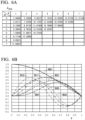
- FIG. 6A and FIG. 6B are views showing examples of the first type Bessel function J m ( ⁇ mk r) included in the criterion function.
- FIG. 6A is a numerical table showing some examples of values of a constant ⁇ mk determined by the subscripts m and k.
- a value of the constant ⁇ mk within a range from 0 to 7 for m and from 1 to a predetermined value according to a value of m for k is shown.
- the value of m of the constant ⁇ mk is 8 or more, and the value of k may be an arbitrary value of one or more.
- the value of the constant ⁇ mk can be easily calculated from the first type m th order of Bessel function J m (r) when m and k are determined.
- FIG. 6B is a view showing some of the first type Bessel functions J m ( ⁇ mk r) determined by the subscripts m and k as a graph within a range of r from 0 to 1.
- a curve line B11 shows a function J 1 ( ⁇ 11 r)
- a curve line B12 shows a function J 1 ( ⁇ 12 r)
- a curve line B21 shows a function J 2 (k 21 r)
- a curve line B22 shows a function J 2 ( ⁇ 22 r)
- a curve line B31 shows a function J 3 ( ⁇ 31 r)
- a curve line B32 shows a function J 3 ( ⁇ 32 r).
- the first type Bessel function included in the criterion function is a function that takes zero with respect to the reference position information IRP of the measured-part MP disposed on the circumferential edge of the substrate WF.
- the first type Bessel function included in the criterion function is a function that takes an extreme value with respect to the reference position information IRP of the measured-part MP disposed at the circumferential edge of the substrate WF.
- the change in the value of the criterion function with respect to the change in r is small. Accordingly, the values of the proportional coefficients ⁇ and ⁇ can be determined without much influence of a local change of the displacement vector DV of the measured-part MP disposed in the vicinity of the outer circumference of the substrate WF.
- the first type Bessel function alone may not be used as a reference function, but may be combined with another reference function.
- it may be used in combination with a reference function using Zernike polynomial as a criterion function.
- fitting can be performed for low-order components using a reference function with a Zernike polynomial as a criterion function, and fitting can be performed for high-order components using a reference function with a first type Bessel function as a criterion function.
- the measuring method of the embodiment measures positions of the plurality of measured-parts MP formed on the substrate WF, and obtains the measured position information IMP of the measured-part MP, i.e., the displacement vector DV of the plurality of measured-parts MP. Then, optimum values of the proportional coefficients ⁇ and ⁇ included in the reference function expressed by Equation (7) and Equation (8) or Equation (15) are calculated by the above-mentioned analyzing method.
- FIG. 7 is a view showing the substrate WF on which a plurality of first patterns A1, outer edges of which are formed in a quadrangular shape by broken lines.
- a plurality of fine patterns (not shown) are formed inside the outer edge of the first pattern A1 shown by a broken line.
- the plurality of measured-parts MP are formed on the substrate WF at positions with predetermined positional relations with respect to the first pattern A1.
- the exposing method of the embodiment measures positions of the plurality of measured-parts MP on the substrate WF using the above-mentioned measuring method of the embodiment, acquires measured position information IMP of the measured-part MP, and calculates optimum value of at least one of the proportional coefficients ⁇ and ⁇ of the above-mentioned reference functions. Then, the position of the first pattern A1 formed on the substrate WF with the predetermined positional relation with respect to the plurality of measured-parts MP is estimated based on the acquired measured position information IMP, and the optimum value of the at least one proportional coefficient.
- the position of the first pattern A1 is estimated based on the reference function in which the optimum values of the proportional coefficients ⁇ and ⁇ are substituted, and the designed position data (AX, AY) of the first pattern A1. That is, the optimum values are substituted into the proportional coefficients ⁇ and ⁇ of the reference function shown by Equation (7) and Equation (8) or Equation (15).
- a position shift amount ⁇ xj in the X direction and a position shift amount ⁇ yj in the Y direction from the designed position are calculated (estimated) by inputting the value of the designed position (Arj, A ⁇ j) in polar coordinates of the j th first pattern A1j to rj and ⁇ j of the reference function.
- the estimated position in the XY coordinates of the j th first pattern A1j is an estimated position (AXj+ ⁇ xj, AYj+ ⁇ yj) where the above-mentioned ⁇ xj and ⁇ yj are added to the designed position (AXj, AYj) in the XY coordinates of the j th first pattern A1j.
- a second pattern (not shown) is exposed to align with the first pattern A 1 on the substrate WF based on the estimated position of the estimated first pattern A1.
- ⁇ xj and ⁇ yj are calculated by substituting the designed position (AXj, AYj) in the XY coordinates of the j th first pattern A1j into Equation (24) to which the values of the parameters a to f determined in this way are substituted. Then, the ⁇ xj and ⁇ yj may be added to the estimated position of the first pattern A1. That is, the estimated position of the first pattern A1 after correction is an estimated position (AXj+ ⁇ xj+ ⁇ xj, AYj+ ⁇ yj+ ⁇ yj).
- the exposing method of the embodiment can be performed using the exposure apparatus 2 of the embodiment as an example.
- the second pattern exposed to the substrate WF in the exposing method of the embodiment is to expose a pattern original plate formed on the mask 25 to the substrate WF via the projection optical system 22.
- the controller 15 may display the fitting result of the measured position information IMP as a vector diagram using a reference function to which the optimum values of the proportional coefficients ⁇ and ⁇ are applied (substituted).
- the vector diagram is a view that displays the deformation amount of the plurality of measured-parts MP on the substrate WF as a vector with the reference position MD of each of the measured-parts MP as the reference (starting point).
- the scale representing the vector may be greatly expanded compared to the scale representing the position of the measured-part MP.
- the vector diagram displayed on the display part 17 may be a vector diagram that indicates a virtual deformation amount of each of the measured-parts MP calculated by the fitted reference function. Alternatively, it may be a vector diagram that indicates a difference between the actual deformation amount (the displacement vector DV) of each of the measured-parts MP and the virtual deformation amount of each of the measured-parts MP calculated by the fitted reference function.
- the controller 15 may obtain information regarding the processing history of the substrate WF which has been analyzed via the network line NW, and analyze correlation between the information regarding the history and the analysis result performed by the analysis part 16. For example, correlation between a processing parameter of an external processing device (etching equipment, a deposition apparatus, chemical mechanical planarization (CMP), or the like), which is used before conveyance of the substrate WF to the measurement apparatus 1 and which is different from the measurement apparatus 1, and the optimum value of the proportional coefficient determined by the analysis part 16 may be taken, feed it back to the processing device, and the processing parameter may be changed and optimized.
- the processing parameter for example, the temperature added to the substrate WF during processing in a processing device, the polishing speed in CMP, or the like, may be changed and optimized.
- the analysis and feedback of such correlation need not necessarily be performed by the controller 15 or the analysis part 16, but may be performed by a host computer provided separately from the measurement apparatus 1 or an external processing device.
- the optimal value of the proportional coefficient determined by the analysis part 16 can be continuously monitored, and a warning can be issued if it exceeds a preset threshold. Abnormalities in external processing devices can be detected by the warning. For example, it is possible to estimate the deterioration (life span) of the electrode in etching equipment. In addition, a flag may be attached to the history of the substrate WF that falls outside the threshold.
- the exposure apparatus 2 of the embodiment determines an operation state of the substrate conveyance device 40 (the load guide 41, the load arm 42, and the substrate chuck part 31) based on the measurement results (the proportional coefficients ⁇ and ⁇ ) obtained by the measuring method of the above-mentioned embodiment.
- the operation state of the substrate conveyance device 40 is, for example, a moving speed of the substrate WF with respect to the substrate chuck part 31 when the substrate WF is placed at the substrate chuck part 31 on the stage 30 or a relative inclination between the substrate WF and the substrate chuck part 31.
- the operation state of the substrate conveyance device 40 may be timing of generation of a holding force for holding the substrate WF on the substrate chuck part 31.
- Change of the timing of generation of the holding force may be change of the timing when the holding force is generated almost all over the surface of the substrate chuck part 31 with respect to the timing of placement of the substrate WF.
- the timing of generation of the holding force in the predetermined portion of the substrate chuck part 31 may be set earlier or later than the timing of generation of the holding force in other parts.
- the exposure apparatus 2 determines a device constant that defines the operation of the substrate conveyance device 40 based on the measurement result (the proportional coefficients ⁇ and ⁇ ) obtained by the measuring method of the embodiment.
- the device constant includes any one of the device constants that determines a moving speed of the substrate WF when the substrate WF is placed on the stage 30, a relative inclination between the substrate WF and the stage 30, or timing of generation of a holding force for holding the substrate WF on the stage 30.
- the change of the device constant may be performed before the substrate WF is removed from the substrate chuck part 31 and the substrate WF is sucked to the substrate chuck part 31 again after the proportional coefficients ⁇ and ⁇ are determined by the measuring method of the embodiment in a state in which the substrate WF is sucked to the stage 30 (the substrate chuck part 31).
- the device constant determined as above for the first substrate WF may be used to expose the second and subsequent substrates WF.
- An analysis part 16 included in the above-mentioned exposure apparatus 2 or measurement apparatus 2 may be incorporated in an analysis apparatus separated from the exposure apparatus 2 or the measurement apparatus 2.
- FIG. 8 is a view schematically showing a configuration of an analysis apparatus 3 of the embodiment.
- the analysis apparatus 3 includes an input part 19, in addition to the analysis part 16, the display part 17, the output part 18, and the position calculator 13, which were described above.
- the analysis apparatus 3 configured separately from the exposure apparatus 2 or the measurement apparatus 2, at least one of the position calculator 13 and the display part 17 may not be included.
- the measured position information IMP that is position information measured by the plurality of measured-parts formed on the substrate WF is input to the analysis apparatus 3 from the input part 19, and the analysis apparatus 3 outputs the optimum value calculated by the analysis part 16 from the output part 18 to the external device such as the exposure apparatus, the measurement apparatus, the display device, or the like.
- the measured position information IMP may be input to the input part 19 via the network line NW or via a dedicated signal line provided between the input part 19 and the external device.
- Output from the output part 18 to the external device may also be performed via the network line NW, or via a dedicated signal line provided between the output part 18 and the external device.
- the input part 19 and the output part 18 may be configured integrally as an input/output part.
- the analysis apparatus 3 may output not only the optimum value as the analysis result, but also data corresponding to the various vector diagrams described above and other processing results.
- the deformation of the substrate WF can be easily separated into deformation components corresponding to the criterion function, and the deformation amount in the deformation mode corresponding to the criterion function can be analyzed.
- the analysis apparatus 3 of the embodiment includes the input part 19 configured to input the measured position information IMP that is position information of the plurality of measured-parts formed on the substrate WF, the analysis part 16 configured to analyze the measured position information IMP of the measured-part MP that was measured by the position measurement part, and the output part 18 configured to output the analysis results including at least a calculated optimum value of a proportional coefficient to external equipment. Then, the analysis part 16 calculates an optimum value of at least one of the proportional coefficient using the analyzing method of the above-mentioned embodiment or variant.
- the deformation of the substrate WF can be easily separated into deformation components corresponding to the criterion function, and the deformation amount in the deformation mode corresponding to the criterion function can be analyzed.
- the measuring method of the embodiment includes measuring positions of the plurality of measured-parts MP formed on the substrate WF, obtaining the measured position information IMP of the measured-part MP, and calculating an optimum value of at least one of the proportional coefficient in the reference function that is the sum of the at least one function obtained by multiplying the criterion function expressed using the first type Bessel function by the proportional coefficient through the analyzing method of the embodiment or variant.
- the deformation of the substrate WF can be measured for each deformation component corresponding to the criterion function.
- the measurement apparatus 1 of the embodiment includes the position measurement part 10 configured to measure the position of the measured-part MP formed on the substrate WF, and the analysis part 16 configured to analyze the measured position information IMP of the measured-part MP that is measured by the position measurement part 10, and the analysis part 16 calculates an optimum value of at least one of the proportional coefficient in the reference function that is the sum of the at least one function obtained by multiplying the criterion function expressed using the first type Bessel function by the proportional coefficient through the analyzing method of the embodiment or variant.
- the deformation of the substrate WF can be measured for each deformation component corresponding to the criterion function.
- the exposing method of the embodiment includes measuring positions of the plurality of measured-parts MP on the substrate WF using the measuring method of the embodiment, acquiring the measured position information IMP of the measured-part, and calculating an optimum value of at least one of the proportional coefficient in the reference function that is the sum of the at least one function obtained by multiplying the criterion function expressed using the first type Bessel function by the proportional coefficient. Then, the position of the first pattern A1 formed on the substrate WF with a predetermined positional relation with respect to the plurality of measured-parts MP is estimated based on the acquired measured position information IMP and the optimum value of at least one of the proportional coefficient, and the second pattern is exposed on the substrate WF based on the estimated position of the first pattern.
- the second pattern can be exposed by aligning the positions to the first pattern A1 formed on the deformed substrate WF.
- the exposure apparatus 2 of the embodiment includes the position measurement part 10 configured to measure a position of the measured-part MP formed on the substrate WF, and the exposure optical system 20 configured to expose a desired pattern on the substrate WF, and performs the exposing method of the embodiment.
- the second pattern can be exposed by aligning the positions to the first pattern A1 formed on the deformed substrate WF with a predetermined positional relation with respect to the measured-part MP.
- the exposure apparatus 2 of the embodiment includes the stage 30 configured to place and move the substrate WF on which the measured-part MP is formed, and the substrate conveyance device 40 configured to convey the substrate WF and place the substrate WF on the stage 30, and the exposure apparatus 2 exposes a desired pattern on the substrate WF, a device constant that defines an operation of the substrate conveyance device 40 is determined based on a measurement result obtained by the measuring method of the embodiment.
- the substrate WF in a state in which the deformation of the substrate WF is reduced, the substrate WF can be placed on the stage 30, and the second pattern can be exposed by aligning the positions more with respect to the first pattern A1 formed on the substrate WF.
- the present invention is not limited to the above-mentioned contents. Other aspects that can be considered within the scope of the technical scope of the present invention are also included within the scope of the present invention. This embodiment may combine all or some of the above-mentioned aspects.
Landscapes
- Physics & Mathematics (AREA)
- General Physics & Mathematics (AREA)
- Engineering & Computer Science (AREA)
- Multimedia (AREA)
- Health & Medical Sciences (AREA)
- Environmental & Geological Engineering (AREA)
- Epidemiology (AREA)
- Public Health (AREA)
- Exposure And Positioning Against Photoresist Photosensitive Materials (AREA)
- Exposure Of Semiconductors, Excluding Electron Or Ion Beam Exposure (AREA)
Applications Claiming Priority (2)
| Application Number | Priority Date | Filing Date | Title |
|---|---|---|---|
| JP2021073425 | 2021-04-23 | ||
| PCT/JP2022/017371 WO2022224845A1 (ja) | 2021-04-23 | 2022-04-08 | 解析方法、解析装置、計測方法、計測装置、露光方法、および露光装置 |
Publications (2)
| Publication Number | Publication Date |
|---|---|
| EP4328544A1 true EP4328544A1 (de) | 2024-02-28 |
| EP4328544A4 EP4328544A4 (de) | 2025-07-23 |
Family
ID=83722956
Family Applications (1)
| Application Number | Title | Priority Date | Filing Date |
|---|---|---|---|
| EP22791619.4A Pending EP4328544A4 (de) | 2021-04-23 | 2022-04-08 | Analyseverfahren, analysevorrichtung, messverfahren, messvorrichtung, belichtungsverfahren und belichtungsvorrichtung |
Country Status (6)
| Country | Link |
|---|---|
| US (1) | US12535747B2 (de) |
| EP (1) | EP4328544A4 (de) |
| JP (1) | JP7601216B2 (de) |
| KR (1) | KR20230159525A (de) |
| TW (1) | TW202246914A (de) |
| WO (1) | WO2022224845A1 (de) |
Family Cites Families (10)
| Publication number | Priority date | Publication date | Assignee | Title |
|---|---|---|---|---|
| JPH0878311A (ja) * | 1994-07-08 | 1996-03-22 | Nikon Corp | 露光方法及び露光装置 |
| US6664121B2 (en) * | 2002-05-20 | 2003-12-16 | Nikon Precision, Inc. | Method and apparatus for position measurement of a pattern formed by a lithographic exposure tool |
| JP5105135B2 (ja) * | 2005-06-28 | 2012-12-19 | 株式会社ニコン | 推定方法、露光方法、デバイス製造方法、検査方法、デバイス製造装置、及びプログラム |
| US9360858B2 (en) * | 2011-08-08 | 2016-06-07 | Globalfoundries Inc. | Alignment data based process control system |
| WO2015113724A1 (en) * | 2014-02-03 | 2015-08-06 | Asml Netherlands B.V. | Metrology method and apparatus, substrate, lithographic system and device manufacturing method |
| KR101890793B1 (ko) | 2014-06-12 | 2018-08-22 | 에이에스엠엘 네델란즈 비.브이. | 리소그래피 장치 및 노광 방법 |
| CN119414655A (zh) | 2016-08-24 | 2025-02-11 | 株式会社 尼康 | 基板处理系统、以及元件制造方法 |
| EP3627228B1 (de) * | 2017-09-28 | 2026-01-14 | ASML Netherlands B.V. | Lithografisches verfahren |
| KR102745234B1 (ko) * | 2019-09-03 | 2024-12-23 | 에이에스엠엘 네델란즈 비.브이. | 패턴들의 수차 감도를 결정하는 방법 |
| JP7391897B2 (ja) | 2019-11-06 | 2023-12-05 | 東芝ライフスタイル株式会社 | 冷蔵庫 |
-
2022
- 2022-04-08 EP EP22791619.4A patent/EP4328544A4/de active Pending
- 2022-04-08 KR KR1020237035768A patent/KR20230159525A/ko active Pending
- 2022-04-08 JP JP2023516441A patent/JP7601216B2/ja active Active
- 2022-04-08 WO PCT/JP2022/017371 patent/WO2022224845A1/ja not_active Ceased
- 2022-04-12 TW TW111113847A patent/TW202246914A/zh unknown
-
2023
- 2023-10-20 US US18/382,256 patent/US12535747B2/en active Active
Also Published As
| Publication number | Publication date |
|---|---|
| JPWO2022224845A1 (de) | 2022-10-27 |
| KR20230159525A (ko) | 2023-11-21 |
| US12535747B2 (en) | 2026-01-27 |
| JP7601216B2 (ja) | 2024-12-17 |
| TW202246914A (zh) | 2022-12-01 |
| EP4328544A4 (de) | 2025-07-23 |
| WO2022224845A1 (ja) | 2022-10-27 |
| US20240045348A1 (en) | 2024-02-08 |
Similar Documents
| Publication | Publication Date | Title |
|---|---|---|
| JP4715749B2 (ja) | アライメント情報表示方法とそのプログラム、アライメント方法、露光方法、デバイス製造方法、表示システム、表示装置 | |
| EP3582011B1 (de) | Informationsverarbeitungsvorrichtung, verfahren, programm, lithografiesystem und herstellungsverfahren für artikel | |
| JP6543761B2 (ja) | リソグラフィ装置及びデバイス製造方法 | |
| KR20010109212A (ko) | 평가방법, 위치검출방법, 노광방법 및 디바이스 제조방법,및 노광장치 | |
| JP7732057B2 (ja) | 情報処理装置、及び情報処理方法 | |
| US6456374B1 (en) | Exposure apparatus and a device manufacturing method using the same | |
| EP4328544A1 (de) | Analyseverfahren, analysevorrichtung, messverfahren, messvorrichtung, belichtungsverfahren und belichtungsvorrichtung | |
| US20130148091A1 (en) | Lithography apparatus and method, and method of manufacturing article | |
| EP2917785B1 (de) | Lithographischer apparat und verfahren zur herstellung einer vorrichtung | |
| JP2009170612A (ja) | 情報処理装置、情報処理方法、処理システムおよびコンピュータプログラム | |
| JP7339826B2 (ja) | マーク位置決定方法、リソグラフィー方法、物品製造方法、プログラムおよびリソグラフィー装置 | |
| US8212990B2 (en) | Exposure apparatus, information processing apparatus, and method of manufacturing device | |
| JP7775032B2 (ja) | 情報処理装置、リソグラフィ装置、情報処理方法、物品の製造方法、およびプログラム | |
| KR20240133591A (ko) | 정보처리장치 및 프로그램 | |
| TWI913511B (zh) | 資訊處理裝置、微影裝置、資訊處理方法、物品的製造方法、及記憶媒體 | |
| US20240385534A1 (en) | Measuring method, lithography method, article manufacturing method, storage medium, and lithography apparatus | |
| TW202424658A (zh) | 資訊處理設備、資訊處理方法、儲存媒體、曝光設備、曝光方法及物品製造方法 | |
| JP2024032636A (ja) | 情報処理装置、情報処理方法、プログラム、露光装置、露光方法、および物品の製造方法 | |
| JP2024507079A (ja) | リソグラフィ装置のための新しいインターフェイス定義 | |
| JP2025118156A (ja) | 計測方法、位置合わせ方法、処理方法、処理装置、物品の製造方法、決定方法及びプログラム | |
| CN117631467A (zh) | 信息处理装置、信息处理方法、存储介质、曝光装置、曝光方法和物品制造方法 |
Legal Events
| Date | Code | Title | Description |
|---|---|---|---|
| STAA | Information on the status of an ep patent application or granted ep patent |
Free format text: STATUS: THE INTERNATIONAL PUBLICATION HAS BEEN MADE |
|
| PUAI | Public reference made under article 153(3) epc to a published international application that has entered the european phase |
Free format text: ORIGINAL CODE: 0009012 |
|
| STAA | Information on the status of an ep patent application or granted ep patent |
Free format text: STATUS: REQUEST FOR EXAMINATION WAS MADE |
|
| 17P | Request for examination filed |
Effective date: 20231027 |
|
| AK | Designated contracting states |
Kind code of ref document: A1 Designated state(s): AL AT BE BG CH CY CZ DE DK EE ES FI FR GB GR HR HU IE IS IT LI LT LU LV MC MK MT NL NO PL PT RO RS SE SI SK SM TR |
|
| DAV | Request for validation of the european patent (deleted) | ||
| DAX | Request for extension of the european patent (deleted) | ||
| A4 | Supplementary search report drawn up and despatched |
Effective date: 20250624 |
|
| RIC1 | Information provided on ipc code assigned before grant |
Ipc: G01B 21/00 20060101AFI20250617BHEP Ipc: G03F 7/20 20060101ALI20250617BHEP Ipc: G03F 7/00 20060101ALI20250617BHEP Ipc: G03F 9/00 20060101ALI20250617BHEP |