EP4329123A2 - Encapsulation de composants et circuit à faible énergie pour emplacements dangereux - Google Patents
Encapsulation de composants et circuit à faible énergie pour emplacements dangereux Download PDFInfo
- Publication number
- EP4329123A2 EP4329123A2 EP23206798.3A EP23206798A EP4329123A2 EP 4329123 A2 EP4329123 A2 EP 4329123A2 EP 23206798 A EP23206798 A EP 23206798A EP 4329123 A2 EP4329123 A2 EP 4329123A2
- Authority
- EP
- European Patent Office
- Prior art keywords
- compressor
- encapsulation material
- sparking component
- sparking
- relay
- Prior art date
- Legal status (The legal status is an assumption and is not a legal conclusion. Google has not performed a legal analysis and makes no representation as to the accuracy of the status listed.)
- Pending
Links
- 238000005538 encapsulation Methods 0.000 title claims abstract description 57
- 231100001261 hazardous Toxicity 0.000 title description 17
- 239000000463 material Substances 0.000 claims abstract description 58
- 238000001816 cooling Methods 0.000 claims abstract description 6
- 238000004519 manufacturing process Methods 0.000 claims abstract 2
- 238000004378 air conditioning Methods 0.000 claims description 15
- 238000000034 method Methods 0.000 claims description 13
- 239000007788 liquid Substances 0.000 claims description 7
- 238000005266 casting Methods 0.000 claims description 3
- 239000007789 gas Substances 0.000 description 21
- 239000007787 solid Substances 0.000 description 20
- 238000005057 refrigeration Methods 0.000 description 9
- 238000004880 explosion Methods 0.000 description 8
- 239000003990 capacitor Substances 0.000 description 6
- 238000010586 diagram Methods 0.000 description 6
- 229920005749 polyurethane resin Polymers 0.000 description 6
- 239000012812 sealant material Substances 0.000 description 5
- 239000004590 silicone sealant Substances 0.000 description 5
- KFZMGEQAYNKOFK-UHFFFAOYSA-N Isopropanol Chemical compound CC(C)O KFZMGEQAYNKOFK-UHFFFAOYSA-N 0.000 description 3
- 230000008878 coupling Effects 0.000 description 3
- 238000010168 coupling process Methods 0.000 description 3
- 238000005859 coupling reaction Methods 0.000 description 3
- 239000000565 sealant Substances 0.000 description 3
- 238000005476 soldering Methods 0.000 description 3
- 238000012986 modification Methods 0.000 description 2
- 230000004048 modification Effects 0.000 description 2
- 229920003023 plastic Polymers 0.000 description 2
- 239000004033 plastic Substances 0.000 description 2
- 238000010926 purge Methods 0.000 description 2
- QVGXLLKOCUKJST-UHFFFAOYSA-N atomic oxygen Chemical compound [O] QVGXLLKOCUKJST-UHFFFAOYSA-N 0.000 description 1
- 238000004140 cleaning Methods 0.000 description 1
- 239000012459 cleaning agent Substances 0.000 description 1
- 238000010276 construction Methods 0.000 description 1
- 239000000428 dust Substances 0.000 description 1
- 230000005611 electricity Effects 0.000 description 1
- 238000007373 indentation Methods 0.000 description 1
- 239000001301 oxygen Substances 0.000 description 1
- 229910052760 oxygen Inorganic materials 0.000 description 1
- 229920001296 polysiloxane Polymers 0.000 description 1
- 238000007789 sealing Methods 0.000 description 1
- 229910000679 solder Inorganic materials 0.000 description 1
Images


Classifications
-
- H—ELECTRICITY
- H01—ELECTRIC ELEMENTS
- H01H—ELECTRIC SWITCHES; RELAYS; SELECTORS; EMERGENCY PROTECTIVE DEVICES
- H01H9/00—Details of switching devices, not covered by groups H01H1/00 - H01H7/00
- H01H9/02—Bases, casings, or covers
- H01H9/04—Dustproof, splashproof, drip-proof, waterproof, or flameproof casings
- H01H9/042—Explosion-proof cases
-
- F—MECHANICAL ENGINEERING; LIGHTING; HEATING; WEAPONS; BLASTING
- F25—REFRIGERATION OR COOLING; COMBINED HEATING AND REFRIGERATION SYSTEMS; HEAT PUMP SYSTEMS; MANUFACTURE OR STORAGE OF ICE; LIQUEFACTION SOLIDIFICATION OF GASES
- F25B—REFRIGERATION MACHINES, PLANTS OR SYSTEMS; COMBINED HEATING AND REFRIGERATION SYSTEMS; HEAT PUMP SYSTEMS
- F25B31/00—Compressor arrangements
-
- H—ELECTRICITY
- H01—ELECTRIC ELEMENTS
- H01H—ELECTRIC SWITCHES; RELAYS; SELECTORS; EMERGENCY PROTECTIVE DEVICES
- H01H35/00—Switches operated by change of a physical condition
- H01H35/24—Switches operated by change of fluid pressure, by fluid pressure waves, or by change of fluid flow
- H01H35/26—Details
-
- H—ELECTRICITY
- H01—ELECTRIC ELEMENTS
- H01H—ELECTRIC SWITCHES; RELAYS; SELECTORS; EMERGENCY PROTECTIVE DEVICES
- H01H45/00—Details of relays
- H01H45/14—Terminal arrangements
-
- H—ELECTRICITY
- H01—ELECTRIC ELEMENTS
- H01H—ELECTRIC SWITCHES; RELAYS; SELECTORS; EMERGENCY PROTECTIVE DEVICES
- H01H9/00—Details of switching devices, not covered by groups H01H1/00 - H01H7/00
- H01H9/02—Bases, casings, or covers
- H01H9/04—Dustproof, splashproof, drip-proof, waterproof, or flameproof casings
-
- H—ELECTRICITY
- H02—GENERATION; CONVERSION OR DISTRIBUTION OF ELECTRIC POWER
- H02H—EMERGENCY PROTECTIVE CIRCUIT ARRANGEMENTS
- H02H7/00—Emergency protective circuit arrangements specially adapted for specific types of electric machines or apparatus or for sectionalised protection of cable or line systems, and effecting automatic switching in the event of an undesired change from normal working conditions
- H02H7/20—Emergency protective circuit arrangements specially adapted for specific types of electric machines or apparatus or for sectionalised protection of cable or line systems, and effecting automatic switching in the event of an undesired change from normal working conditions for electronic equipment
-
- F—MECHANICAL ENGINEERING; LIGHTING; HEATING; WEAPONS; BLASTING
- F25—REFRIGERATION OR COOLING; COMBINED HEATING AND REFRIGERATION SYSTEMS; HEAT PUMP SYSTEMS; MANUFACTURE OR STORAGE OF ICE; LIQUEFACTION SOLIDIFICATION OF GASES
- F25B—REFRIGERATION MACHINES, PLANTS OR SYSTEMS; COMBINED HEATING AND REFRIGERATION SYSTEMS; HEAT PUMP SYSTEMS
- F25B2400/00—General features or devices for refrigeration machines, plants or systems, combined heating and refrigeration systems or heat-pump systems, i.e. not limited to a particular subgroup of F25B
- F25B2400/12—Inflammable refrigerants
-
- H—ELECTRICITY
- H01—ELECTRIC ELEMENTS
- H01H—ELECTRIC SWITCHES; RELAYS; SELECTORS; EMERGENCY PROTECTIVE DEVICES
- H01H37/00—Thermally-actuated switches
- H01H37/02—Details
- H01H37/04—Bases; Housings; Mountings
-
- H—ELECTRICITY
- H01—ELECTRIC ELEMENTS
- H01H—ELECTRIC SWITCHES; RELAYS; SELECTORS; EMERGENCY PROTECTIVE DEVICES
- H01H50/00—Details of electromagnetic relays
- H01H50/02—Bases; Casings; Covers
- H01H50/023—Details concerning sealing, e.g. sealing casing with resin
Definitions
- the present disclosure relates generally to air conditioning units for use in a hazardous environment where flammable gases or vapors may exist.
- the present disclosure relates to air conditioning units which prevent gases from being ignited by encapsulating sparking components, using solid-state switching devices, and/or wiring circuits in such a way that open contacts do not contain enough energy to produce a spark capable of igniting the atmosphere.
- explosion-proofing techniques included creating a purged and pressurized system to create a non-hazardous environment, or adding a large cast explosion proof enclosure to contain any undesired explosions and placing any sparking devices within the explosion proof enclosure.
- these explosion proof techniques were unduly complicated and expensive because purge and pressurization devices required shop air, and large cast explosion proof enclosures are bulky and expensive. Further, these bulky enclosures significantly increased the size of the hazardous location rated air conditioners.
- the present disclosure includes a compressor overload for use with air conditioning or refrigeration systems in a hazardous location where flammable gases or vapors may exist, comprising: a thermal sensor, at least one overload terminal, a base bracket, a disc, at least one wire configured to attach to the at least one overload terminal, and encapsulation material wherein the encapsulation material forms an air tight cover surrounding the compressor overload.
- the present disclosure also includes a compressor start relay for use with air conditioning or refrigeration systems in a hazardous location where flammable gases or vapors may exist, comprising at least one relay terminal, at least one wire coupled onto the at least one relay terminal, and encapsulation material wherein the encapsulation material forms an air tight cover completely surrounding the compressor start relay.
- the present disclosure includes a wiring circuit for air conditioning or refrigeration systems in a hazardous location where flammable gases or vapors may exist, comprising a compressor, a transformer, a high energy circuit, a low energy circuit, a solid state relay wherein a first portion of the solid state relay is configured to connect to the high energy circuit and a second portion of the solid state relay is configured to connect to the low energy circuit, and a line voltage.
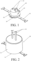
- a compressor overload 10, a compressor start relay 30 and a pressure switch 50 are each components which can form a part of an air conditioning unit. Any of these components have the potential to create a spark during ordinary use. A spark could lead to an explosion if any of these components are used in a hazardous location where ignitable concentrations of flammable gases or vapors may be present. Therefore, it is desirable to encapsulate these components within an air tight material to prevent any potential sparks from mixing with flammable gases or vapors which may exist in the surrounding environment.
- FIG. 1 shows one embodiment of a compressor overload 10 having a thermal sensor 12, overload terminals 14, a base bracket 16 and a disc 18.
- the disc 18 is configured to be coupled to the base bracket 16.
- the disc 18 can be rotated and locked into the base bracket 16.
- wires 19 (shown in FIG. 2 ) can be attached to the overload terminals 14.
- the wires 19 can be coupled to the overload terminals 14 by soldering them onto the terminals 14 or by various other attachment means known in the art.
- FIG. 2 shows an embodiment of an encapsulated compressor overload 20.
- components of the compressor overload 10 such as the thermal sensor 12, overload terminals 14 and disc 18 are completely covered by the encapsulation material 22.
- the encapsulation material 22 can also cover a portion of the base bracket 16 and a portion of the wires 19.
- Various other combinations can be used where different combinations of components can be enclosed by the encapsulation material 22 as long as the components which are capable of creating a spark are completely contained within the encapsulation material 22.
- the encapsulation material 22 forms an air tight cover surrounding the compressor overload 10. In one embodiment the encapsulation material 22 forms a cylindrical cover over the thermal sensor 12, overload terminals 14, base bracket 16 and disc 18.
- various different shapes can be used for the encapsulation material 22 as long as the shape creates an air tight seal over the potential sparking components. The requirement of an air tight seal also applies where the base bracket 16 and wires 19 extend up to or through the encapsulation material 22.
- the bottom surface 24 of the base bracket 16 is not covered by the encapsulation material 22 and sits flush with the encapsulation material 22.
- the thermal sensor 12 is located next to the base bracket 16, which is thermally conductive, to allow the thermal sensor 12 to sense temperature through the bracket 16.
- the bottom surface 24 of the base bracket 16 is not covered by any encapsulation material 22 to allow the thermal sensor 12 to sense temperature through the base bracket 16.
- the following steps can be used to encapsulate a compressor overload 10.
- a user can take a compressor overload 10 and attach wires 19 to the overload terminals 14 of the compressor.
- This form of attachment includes but is not limited to direct coupling or soldering.
- the base bracket 16 and disc 18 can be cleaned with a cleaning agent such as isopropyl alcohol before being coupled together. After cleaning the base bracket 16 and disc 18, the user can rotate the disc 18 into the base bracket 16 and lock the bracket 16 and disc 18 together via various forms of engagement which are known in the art.
- this form of engagement includes a protrusion on the disc 18 engaging an indentation on the bracket 16.
- the user can also substantially or completely cover all the electrically live parts of the compressor overload 10 with a silicone sealant which can be flame resistant.
- An electrically live part is any part which has electricity flowing through it.
- this flame resistant sealant has a thickness sufficient to meet the UL 94 V-0 minimum flammability rating which is a standard that classifies plastics according to how they burn in various orientations and thicknesses.
- the UL 94 V-0 is a plastics flammability standard released by Underwriters Laboratories of the USA. In one embodiment this minimum thickness is 5.4 millimeters.
- the user can locate or otherwise create a casting or mold in a desired shape for the encapsulation material 22. In the embodiment shown in FIG. 2 , the mold has a cylindrical shape but it should be understood to one of ordinary skill in the art that various other shapes can be used as well to suit a user's needs.
- the user After obtaining a mold, the user places the compressor overload 10 and any attached wires 19 inside the mold. The user can then pour liquid encapsulation material into the mold to completely encapsulate the compressor overload 10 and any attached wires 19. After hardening, the encapsulation material 22 creates an air tight seal around the compressor overload 10 and wires 19 to ensure that any potential spark is completely contained within the encapsulation material 22 and cannot interact with any gases or vapors outside the encapsulation material 22.
- the encapsulation material 22 can be a polyurethane resin and/or can have a thickness of one-quarter inch all around. In another one embodiment, the encapsulation material 22 can be poured to be flush with the bottom surface 24 of the base bracket 16.
- FIG. 3 shows a wire diagram of one embodiment of a compressor potential start relay 30 having relay terminals 32, a first wire 34, a second wire 36 and a third wire 38.
- the compressor start relay 30 is not solely limited to the use of three wires as shown in FIG. 3 , but can use a varying number of wires.
- the first 34, second 36, and third 38 wires can be attached to individual relay terminals 32.
- the wires 34, 36, 38 can be coupled to the relay terminals 32 by soldering them onto the terminals 14 or by various other attachment means known in the art.
- FIG. 4 shows one embodiment of an encapsulated compressor start relay 40.
- the compressor start relay 30 and relay terminals 32 are completely covered by the encapsulation material 22.
- the encapsulation material 22 can also cover a portion of the wires 34, 36, 38.
- the encapsulation material 22 creates an air tight seal over any potential sparking components. While FIG. 4 shows a boxed shape for the encapsulation material 22, it is understood that any shape which creates an air tight seal over the potential sparking components can be used. The requirement of an air tight seal also applies where the wires 34, 36, 38 extend through the encapsulation material 22.
- the following process can be used to encapsulate a compressor start relay 30.
- a user can take a compressor start relay 30 and solder or otherwise attach wires 34, 36, 38 to the individual relay terminals 32 of the start relay 30.
- the user can also substantially or completely cover all the electrically live parts of the compressor start relay 30 with a flame resistant sealant such as silicone.
- this flame resistant sealant has a thickness sufficient to meet the UL 94 V-0 minimum flammability rating minimum which in one instance can be 5.4 millimeters.
- the user can locate or otherwise create a casting or mold in a desired shape for the encapsulation material 22.
- the mold has a boxed shape with a flange at one end, but it should be understood to one of ordinary skill in the art that various other shapes could be used as well.
- the user After obtaining a mold, the user places the compressor start relay 30 with wires 34, 36, 38 inside the mold. The user can then pour liquid encapsulation material into the mold to completely encapsulate the compressor start relay 30 and wires 34, 36, 38.
- the encapsulation material 22 creates an air tight seal around the compressor start relay 30 and wires 34, 36, 38 to ensure that any potential spark is completely contained within the encapsulation material 22 and cannot interact with any gases or vapors outside the encapsulation material 22.
- the encapsulation material 22 can be a polyurethane resin and can have a thickness of one-quarter inch all around.
- FIG. 5 illustrates one embodiment of a pressure switch 50 having a body portion 51, a first wire 52 with a first connector 54, a second wire 56 with a second connector 58, heat shrink tubing 60, and a third connector 62. It should be understood to one of ordinary skill in the art that the pressure switch 50 is not solely limited to the use of two wires as shown in FIG. 5 .
- FIG. 5 shows one embodiment of an encapsulated pressure switch 50.
- the body portion 51 of the pressure switch 50 is surrounded by tube 60.
- the tube 60 can also cover a portion of the wires 52, 56.
- a sealant material such as a polyurethane resin can be applied near the first 64 and second 66 edges of the tubing to create an air tight seal. The sealant material creates an air tight seal where the first wire 52, second wire 56, and third connector 62 extend past the first 64 and second 66 edges of the tubing 60 respectively.
- the sealant material seals the body portion 51, tube 60, first wire 52, second wire 56, and third connector 62 such that these components all rotate together when any of the portion of the body portion 51, tube 60, first wire 52, second wire 56, or third connector 62 is rotated.
- the following process can be used to encapsulate a pressure switch 50.
- a user can take a pressure switch 50 and place heat shrink tubing 60 over a body portion 51 of the pressure switch 50.
- the heat shrink tubing 60 should extend past and cover all the components within the body portion 51 which can create a spark.
- the user can apply heat to the tubing 60 to shrink it down and conform the tubing 60 to the body portion 51 of the switch 50.
- the user can also apply a sealant material such as a polyurethane resin near the first 64 and second 66 edges of the tubing 60.
- the sealant material should not exceed the first 64 and second 66 edges of the tubing 60 and combined with the tubing 60, should create a completely air tight seal around the body 51 of the pressure switch 50.
- Creating an air tight seal around the body 51 should completely seal off the sparking components within the heat shrink tubing 60 which eliminates the risk that these sparking components could ignite nearby flammable gases or vapors present in a hazardous location.
- a user By sealing off the sparking components 10, 30, 50 individually, a user avoids having to use alternative safeguards such as a purged and pressurized air system to prevent hazardous outside air from coming into contact with a spark.
- a purged and pressurized air system can be both complicated and expensive.
- a user also avoids having to use an alternative such as building out a large cast explosion-proof enclosure and placing all of the sparking components within this enclosure. Placing all of the potential sparking components in a single enclosure requires reconfiguring the overall size and shape of the air conditioner to accommodate having all the sparking components in one central location.
- the present disclosure allows a user to seal off each sparking component individually and therefore allows a user to avoid having to install a purged and pressurized air system, thus enabling the user to maintain the same overall size and shape of a non-hazardous location air conditioner. This results in a lower overall cost and creates a compact self-contained cooling device.
- Another way to provide protection against the potential ignition of flammable gases or vapors is to wire the air conditioner to make use of a low energy circuit where the energy is a function of the voltage and current in a circuit.
- the low energy circuit is sufficiently low in energy such that it does not contain enough energy to produce a spark capable of igniting the surrounding atmosphere.
- FIG. 6 illustrates a wiring diagram of an air conditioning unit according to the prior art.
- the wiring for the compressor 70 uses high voltage throughout the entirety of its circuit and thus is powered by a high energy circuit.
- the compressor 70 is directly connected to a compressor start relay 76, which in turn is connected to a compressor start capacitor 78.
- the compressor start capacitor 78 is connected to the compressor 70 which is also wired to a mechanical contactor 80.
- the mechanical contactor 80 is directly connected to the line voltage 74.
- the compressor 70 is connected to the line voltage 74 and uses high voltage throughout its circuit. Because the compressor wiring uses high voltage throughout its circuit, there is a potential for a spark to be created in the compressor start relay 76 between connection points 82, 84. To remove the potential for a spark, the compressor wiring can be reconfigured as shown in FIG. 7 .
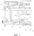
- FIG. 7 illustrates a wiring diagram of one embodiment of an air conditioning unit where a low energy circuit has been introduced into the compressor wiring. That same principles discussed below would also apply to wiring for a refrigeration unit.
- the wiring for the compressor 170 uses both high voltage and low voltage.
- the compressor 170 is connected to a first solid state relay 188 and a compressor start relay 176.
- the compressor start relay 176 is connected to a second solid state relay 192.
- a first side 190 of the second solid state relay 192 is connected to the secondary side of the step down transformer 172 and thus operates on low voltage.
- a second side 194 of the second solid state relay 192 is wired to a start capacitor 178, which is connected to line voltage 175, and therefore it operates on high voltage.
- the line connections between the connection points 182, 184 of the compressor start relay 176 and the first side 190 of the second solid state relay 192 all use low voltage and therefore operate on a low energy circuit.
- the second side 194 of the second solid state relay 192 is connected to the start capacitor 178, which in turn is connected to the line voltage 175. Therefore, the second side 194 of the second solid state relay 192 operates on high voltage and a high energy circuit because it is powered by line voltage 175.
- connection points 182, 184 are now wired to the secondary side of the step down transformer 172.
- the line voltage 174 on the primary side of the transformer is 115 volts and the low voltage on the secondary side of the transformer 172 is 24 volts.
- the connection points 182, 184 are now wired using low voltage which does not contain enough energy to produce a spark capable of igniting the gases and vapors in the surrounding hazardous environment.
- an overcurrent relay 196 is added to the circuit in order to provide protection against excessive currents.
- the mechanical contactor 80 shown in FIG. 6
- a solid state relay 188 which does not create a spark potential.
- the low energy circuit eliminates the need for any type of encapsulation, explosion-proof enclosure or purge and pressurization device.
Landscapes
- Engineering & Computer Science (AREA)
- Physics & Mathematics (AREA)
- Mechanical Engineering (AREA)
- Thermal Sciences (AREA)
- General Engineering & Computer Science (AREA)
- Power Engineering (AREA)
- Electromagnetism (AREA)
- Fluid Mechanics (AREA)
- Compressor (AREA)
- Motor Or Generator Cooling System (AREA)
Applications Claiming Priority (3)
| Application Number | Priority Date | Filing Date | Title |
|---|---|---|---|
| US14/488,150 US9559517B2 (en) | 2014-09-16 | 2014-09-16 | Encapsulation of components and a low energy circuit for hazardous locations |
| EP15842173.5A EP3195450B1 (fr) | 2014-09-16 | 2015-09-15 | Encapsulation de composants et circuit à faible énergie pour emplacements dangereux |
| PCT/US2015/050265 WO2016044322A1 (fr) | 2014-09-16 | 2015-09-15 | Encapsulation de composants et circuit à faible énergie pour emplacements dangereux |
Related Parent Applications (1)
| Application Number | Title | Priority Date | Filing Date |
|---|---|---|---|
| EP15842173.5A Division EP3195450B1 (fr) | 2014-09-16 | 2015-09-15 | Encapsulation de composants et circuit à faible énergie pour emplacements dangereux |
Publications (2)
| Publication Number | Publication Date |
|---|---|
| EP4329123A2 true EP4329123A2 (fr) | 2024-02-28 |
| EP4329123A3 EP4329123A3 (fr) | 2024-05-22 |
Family
ID=55455409
Family Applications (2)
| Application Number | Title | Priority Date | Filing Date |
|---|---|---|---|
| EP23206798.3A Pending EP4329123A3 (fr) | 2014-09-16 | 2015-09-15 | Encapsulation de composants et circuit à faible énergie pour emplacements dangereux |
| EP15842173.5A Active EP3195450B1 (fr) | 2014-09-16 | 2015-09-15 | Encapsulation de composants et circuit à faible énergie pour emplacements dangereux |
Family Applications After (1)
| Application Number | Title | Priority Date | Filing Date |
|---|---|---|---|
| EP15842173.5A Active EP3195450B1 (fr) | 2014-09-16 | 2015-09-15 | Encapsulation de composants et circuit à faible énergie pour emplacements dangereux |
Country Status (3)
| Country | Link |
|---|---|
| US (2) | US9559517B2 (fr) |
| EP (2) | EP4329123A3 (fr) |
| WO (1) | WO2016044322A1 (fr) |
Families Citing this family (5)
| Publication number | Priority date | Publication date | Assignee | Title |
|---|---|---|---|---|
| US11408622B2 (en) * | 2015-08-27 | 2022-08-09 | Delta T, Llc | Control with enhanced sensing capabilities |
| CN108801854B (zh) * | 2018-06-26 | 2021-04-20 | 南方电网科学研究院有限责任公司 | 一种气体密度测量装置 |
| CN108801853B (zh) * | 2018-06-26 | 2021-04-16 | 南方电网科学研究院有限责任公司 | 一种气体密度测量装置 |
| US12061007B2 (en) * | 2020-02-07 | 2024-08-13 | Carrier Corporation | A2L compliant contactor |
| CN113963988B (zh) * | 2021-11-20 | 2025-07-04 | 山东中道消防设备有限公司 | 一种汽车灭火用k型自恢复式温探器 |
Family Cites Families (62)
| Publication number | Priority date | Publication date | Assignee | Title |
|---|---|---|---|---|
| US3024596A (en) * | 1955-03-16 | 1962-03-13 | Strato Missiles Inc | Propulsion system with automatic control of fuel and air |
| US3514967A (en) * | 1968-06-20 | 1970-06-02 | Whirlpool Co | Air conditioner control |
| US3800111A (en) * | 1971-02-22 | 1974-03-26 | Asea Ab | Electric switching device comprising insulating parts reinforced with polyvinyl alcohol fibres |
| US3911693A (en) * | 1974-05-06 | 1975-10-14 | Friedrich Refrigerators Inc | Hazardous duty room air conditioner |
| US3982405A (en) * | 1974-05-06 | 1976-09-28 | Seigler Jack D | Hazardous duty room air conditioner |
| US3913342A (en) | 1974-07-01 | 1975-10-21 | Carrier Corp | Motor compressor control |
| US4034337A (en) * | 1975-09-09 | 1977-07-05 | Electronic Devices, Inc. | Vehicle alarm apparatus |
| US4038507A (en) * | 1976-02-20 | 1977-07-26 | Frank W. Murphy Manufacturer, Inc. | Oil level regulator and shut-down device for stationary engines and compressors |
| US4205246A (en) | 1978-03-17 | 1980-05-27 | Tecumseh Products Company | Explosion resistant overload and relay mounting for explosion resistant motor |
| US5192194A (en) | 1991-04-23 | 1993-03-09 | Air Engineers, Inc. | Explosion proof compressor and a method for explosion proofing a compressor |
| DE4312736C2 (de) * | 1993-04-20 | 1998-09-10 | Karl Kapfer | Explosionsgeschütztes Microschalterbauteil |
| JPH0755298A (ja) * | 1993-08-20 | 1995-03-03 | Matsushita Electric Ind Co Ltd | 空気調和装置 |
| US5515217A (en) * | 1993-09-22 | 1996-05-07 | Ubukata Industries Co., Ltd. | Thermal protector for hermetic electrically-driven compressors |
| IT1267721B1 (it) * | 1994-05-20 | 1997-02-07 | Zanussi Elettrodomestici | Apparecchio frigorifero con interrutore antiscoppio |
| JPH07310661A (ja) * | 1994-05-20 | 1995-11-28 | Hitachi Ltd | 密閉型電動圧縮機 |
| US5657641A (en) | 1995-09-13 | 1997-08-19 | Kooltronic, Inc. | Panel mounted cooling system |
| IT238871Y1 (it) * | 1995-11-29 | 2000-11-15 | Electrolux Zanussi Elettrodome | Apparecchio frigorifero con interruttore perfezionato |
| US6064064A (en) * | 1996-03-01 | 2000-05-16 | Fire Sentry Corporation | Fire detector |
| CA2208943C (fr) * | 1996-07-26 | 2000-06-06 | Tecumseh Products Company | Support pour coupe-circuit de surcharge thermique pour compresseur et methode de montage de celui-ci |
| FR2760075B1 (fr) | 1997-02-21 | 1999-05-28 | Cryotechnologies | Systeme de conditionnement de composants fonctionnant a temperature cryogenique |
| US6290528B1 (en) * | 1998-07-14 | 2001-09-18 | Carrier Corporation | Electric power supply connector for sealed compressor |
| US6345511B1 (en) | 1999-02-25 | 2002-02-12 | Kooltronic, Incorporated | Air handling apparatus |
| US6542062B1 (en) | 1999-06-11 | 2003-04-01 | Tecumseh Products Company | Overload protector with control element |
| US6370899B1 (en) | 1999-07-28 | 2002-04-16 | Crispaire, A Division Of Airxcel, Inc. | Single package wall mounted HVAC unit |
| US6101829A (en) | 1999-09-20 | 2000-08-15 | Airxcel, Inc. | Air conditioning apparatus |
| JP3600781B2 (ja) * | 2000-06-06 | 2004-12-15 | 株式会社日立製作所 | 密閉形電動圧縮機用保護装置、並びにこれを用いた密閉形電動圧縮機及び冷却システム |
| US6357249B1 (en) | 2001-04-11 | 2002-03-19 | Airxcel, Inc. | Vehicle rooftop air conditioner |
| NL1023425C2 (nl) * | 2003-05-14 | 2004-11-16 | Tno | Werkwijze en inrichting voor de vervaardiging van een vezelversterkt kunststof product. |
| US20060006144A1 (en) * | 2004-07-09 | 2006-01-12 | S & C Electric Co. | Arc-extinguishing composition and articles manufactured therefrom |
| US20080237194A1 (en) * | 2004-07-09 | 2008-10-02 | S & C Electric Co. | Metal-hydrate containing arc-extinguishing compositions and methods |
| JP4580786B2 (ja) | 2005-03-11 | 2010-11-17 | 東芝キヤリア株式会社 | 空気調和機及びシェルタ |
| EP2752629A1 (fr) | 2005-08-04 | 2014-07-09 | EIC Solutions, Inc. | Boîtier de transit thermoélectrique à air conditionné |
| CA2642760A1 (fr) * | 2006-02-13 | 2008-07-10 | Halkey-Roberts Corporation | Appareil et procede d'utilisation de materiau energetique a base de tetrazine |
| KR100875017B1 (ko) * | 2006-04-27 | 2008-12-19 | 파나소닉 주식회사 | 밀폐형 컴프레서 |
| US7798183B2 (en) * | 2006-10-26 | 2010-09-21 | Illinois Tool Works Inc. | Integrated compressor-tire sealant injection device with large mouth sealant container |
| CN201007529Y (zh) | 2007-01-15 | 2008-01-16 | 徐勤新 | 一体式防爆空调机 |
| CN100462638C (zh) | 2007-08-08 | 2009-02-18 | 张品莹 | 防爆空调新风口冷量回收装置 |
| CN201074888Y (zh) | 2007-08-08 | 2008-06-18 | 张品莹 | 防爆空调新风口冷量回收装置 |
| US7929294B2 (en) | 2008-09-11 | 2011-04-19 | Commscope Inc. Of North Carolina | Hybrid cooling system for outdoor electronics enclosure |
| US8600559B2 (en) | 2008-10-27 | 2013-12-03 | Lennox Industries Inc. | Method of controlling equipment in a heating, ventilation and air conditioning network |
| CN201373511Y (zh) | 2009-02-03 | 2009-12-30 | 南阳市一通防爆电气有限公司 | 钻采防爆空调机 |
| EP2295885A1 (fr) | 2009-08-27 | 2011-03-16 | STULZ GmbH | Boîte climatique dotée d'un échangeur thermique et procédé de climatisation |
| CA2938102C (fr) * | 2010-10-05 | 2018-11-27 | Advanced Fusion Systems Llc | Circuit integre de vide a courant eleve et tension elevee |
| CN201934128U (zh) | 2010-12-30 | 2011-08-17 | 南阳市一通防爆电气有限公司 | 煤矿救生舱用防爆空调装置 |
| EP2493277A2 (fr) | 2011-02-22 | 2012-08-29 | Stulz-Chspl (India) PVT, Ltd. | Amélioration du système de refroidissement pour abris de télécommunication |
| JP2012190884A (ja) | 2011-03-09 | 2012-10-04 | Panasonic Corp | ラック型電子機器の冷却装置 |
| EP2503257B9 (fr) | 2011-03-22 | 2014-06-04 | Erwin Gasser | Abri |
| CN201954711U (zh) | 2011-04-05 | 2011-08-31 | 新黎明防爆电器有限公司 | 防爆空调 |
| CN202119052U (zh) | 2011-06-27 | 2012-01-18 | 珠海格力电器股份有限公司 | 防爆空调及其防爆箱的安装结构 |
| CN202145029U (zh) | 2011-07-18 | 2012-02-15 | 珠海格力电器股份有限公司 | 防爆空调器 |
| CN102889638B (zh) | 2011-07-18 | 2015-03-18 | 珠海格力电器股份有限公司 | 防爆空调器 |
| CN202250144U (zh) | 2011-08-23 | 2012-05-30 | 南阳市一通防爆电气有限公司 | 一种柜式煤矿用防爆空气调节器 |
| CN202250143U (zh) | 2011-08-23 | 2012-05-30 | 南阳市一通防爆电气有限公司 | 一种壁挂式煤矿用防爆空气调节器 |
| US9121617B2 (en) | 2012-01-20 | 2015-09-01 | Berg Companies, Inc. | Expandable shelter HVAC systems |
| CN202546936U (zh) | 2012-02-22 | 2012-11-21 | 上海钧华防爆设备有限公司 | 一种集成防爆空调 |
| CN202769872U (zh) | 2012-06-20 | 2013-03-06 | 杭州坚信电气设备有限公司 | 一种防爆空调 |
| US20140000299A1 (en) | 2012-06-28 | 2014-01-02 | Strata Products Worldwide, Llc | Air Conditioner for Refuge Shelter, System and Method |
| CN202902480U (zh) | 2012-10-24 | 2013-04-24 | 江苏兆胜空调有限公司 | 顶置式防爆空调器 |
| CN202902482U (zh) | 2012-10-30 | 2013-04-24 | 江苏兆胜空调有限公司 | 一种顶置式防爆空调器 |
| CN102889646A (zh) | 2012-10-30 | 2013-01-23 | 江苏兆胜空调有限公司 | 一种顶置式防爆空调器 |
| CN103196184B (zh) | 2013-04-25 | 2016-03-23 | 广东志高空调有限公司 | 一种分体式防爆空调器 |
| US9157670B2 (en) | 2013-10-25 | 2015-10-13 | Kooltronic, Inc. | Hazardous location heat transfer unit |
-
2014
- 2014-09-16 US US14/488,150 patent/US9559517B2/en active Active
-
2015
- 2015-09-15 EP EP23206798.3A patent/EP4329123A3/fr active Pending
- 2015-09-15 EP EP15842173.5A patent/EP3195450B1/fr active Active
- 2015-09-15 WO PCT/US2015/050265 patent/WO2016044322A1/fr not_active Ceased
-
2017
- 2017-01-13 US US15/406,422 patent/US10332697B2/en active Active
Also Published As
| Publication number | Publication date |
|---|---|
| EP3195450A1 (fr) | 2017-07-26 |
| US9559517B2 (en) | 2017-01-31 |
| US20160079020A1 (en) | 2016-03-17 |
| EP3195450A4 (fr) | 2018-05-30 |
| WO2016044322A1 (fr) | 2016-03-24 |
| EP4329123A3 (fr) | 2024-05-22 |
| US10332697B2 (en) | 2019-06-25 |
| US20170125181A1 (en) | 2017-05-04 |
| EP3195450C0 (fr) | 2023-11-01 |
| EP3195450B1 (fr) | 2023-11-01 |
Similar Documents
| Publication | Publication Date | Title |
|---|---|---|
| US10332697B2 (en) | Encapsulation of components and a low energy circuit for hazardous locations | |
| US9793049B2 (en) | Protected capacitor system and method | |
| US20170229241A1 (en) | Protected capacitor system and method | |
| US9112349B2 (en) | Electromechanical excess temperature protection element | |
| KR20140103456A (ko) | 소화기능을 갖춘 콘센트 | |
| CN111082605B (zh) | 电机 | |
| CN104704695A (zh) | 具有电连接装置的通风机 | |
| US9754753B2 (en) | Breaker secondary terminal block isolation chamber | |
| CN104078225B (zh) | 互感器 | |
| CN111354611A (zh) | 具有能量耗散盖的密封电池熔断器模块 | |
| JP2016162683A (ja) | 高圧電気回路保護用ヒューズ | |
| NL2034987A (en) | Passive device for protection of the electrical junction box of the LV power supply to a building from undesirable elevated temperature or flame burns. | |
| EP3143632B1 (fr) | Élément interrupteur destiné à être utilisé dans une zone potentiellement explosive | |
| CN103208792B (zh) | 一种带脱扣功能的无续流放电管模块 | |
| CN209195581U (zh) | 一种起动机 | |
| KR101214609B1 (ko) | 고전압차단스위치 | |
| CN1682426B (zh) | 电动机电子控制装置 | |
| CN118675935B (zh) | 一种安装支架、取电组件和柱上断路器 | |
| JP3077444U (ja) | 抵抗器 | |
| CN109510372A (zh) | 一种新型防爆电机接线盒 | |
| JPS63294637A (ja) | 耐塩形カットアウト | |
| JP6780388B2 (ja) | 開閉器、及び開閉器の組立方法 | |
| CN202405754U (zh) | 空调用安全四通阀 | |
| JP6594697B2 (ja) | セラミック複合材料を有ずる電子スイッチ部材 | |
| CN203707967U (zh) | 执行器用隔爆型电机 |
Legal Events
| Date | Code | Title | Description |
|---|---|---|---|
| PUAI | Public reference made under article 153(3) epc to a published international application that has entered the european phase |
Free format text: ORIGINAL CODE: 0009012 |
|
| STAA | Information on the status of an ep patent application or granted ep patent |
Free format text: STATUS: THE APPLICATION HAS BEEN PUBLISHED |
|
| AC | Divisional application: reference to earlier application |
Ref document number: 3195450 Country of ref document: EP Kind code of ref document: P |
|
| AK | Designated contracting states |
Kind code of ref document: A2 Designated state(s): AL AT BE BG CH CY CZ DE DK EE ES FI FR GB GR HR HU IE IS IT LI LT LU LV MC MK MT NL NO PL PT RO RS SE SI SK SM TR |
|
| REG | Reference to a national code |
Ref country code: DE Ref legal event code: R079 Free format text: PREVIOUS MAIN CLASS: H02H0007200000 Ipc: F25D0029000000 |
|
| PUAL | Search report despatched |
Free format text: ORIGINAL CODE: 0009013 |
|
| AK | Designated contracting states |
Kind code of ref document: A3 Designated state(s): AL AT BE BG CH CY CZ DE DK EE ES FI FR GB GR HR HU IE IS IT LI LT LU LV MC MK MT NL NO PL PT RO RS SE SI SK SM TR |
|
| RIC1 | Information provided on ipc code assigned before grant |
Ipc: H02H 7/20 20060101ALI20240417BHEP Ipc: H01H 35/26 20060101ALI20240417BHEP Ipc: H01H 45/14 20060101ALI20240417BHEP Ipc: H01H 37/04 20060101ALI20240417BHEP Ipc: H01H 9/04 20060101ALI20240417BHEP Ipc: H02K 5/136 20060101ALI20240417BHEP Ipc: H01H 13/06 20060101ALI20240417BHEP Ipc: F25B 31/00 20060101ALI20240417BHEP Ipc: F25D 29/00 20060101AFI20240417BHEP |
|
| STAA | Information on the status of an ep patent application or granted ep patent |
Free format text: STATUS: REQUEST FOR EXAMINATION WAS MADE |
|
| 17P | Request for examination filed |
Effective date: 20241122 |
|
| RBV | Designated contracting states (corrected) |
Designated state(s): AL AT BE BG CH CY CZ DE DK EE ES FI FR GB GR HR HU IE IS IT LI LT LU LV MC MK MT NL NO PL PT RO RS SE SI SK SM TR |