EP4330053B1 - Zahn und zugehöriges verfahren - Google Patents
Zahn und zugehöriges verfahren Download PDFInfo
- Publication number
- EP4330053B1 EP4330053B1 EP22721830.2A EP22721830A EP4330053B1 EP 4330053 B1 EP4330053 B1 EP 4330053B1 EP 22721830 A EP22721830 A EP 22721830A EP 4330053 B1 EP4330053 B1 EP 4330053B1
- Authority
- EP
- European Patent Office
- Prior art keywords
- base
- cap
- tooth
- cavity
- recesses
- Prior art date
- Legal status (The legal status is an assumption and is not a legal conclusion. Google has not performed a legal analysis and makes no representation as to the accuracy of the status listed.)
- Active
Links
Images


Classifications
-
- B—PERFORMING OPERATIONS; TRANSPORTING
- B22—CASTING; POWDER METALLURGY
- B22D—CASTING OF METALS; CASTING OF OTHER SUBSTANCES BY THE SAME PROCESSES OR DEVICES
- B22D19/00—Casting in, on, or around objects which form part of the product
- B22D19/16—Casting in, on, or around objects which form part of the product for making compound objects cast of two or more different metals, e.g. for making rolls for rolling mills
-
- B—PERFORMING OPERATIONS; TRANSPORTING
- B60—VEHICLES IN GENERAL
- B60B—VEHICLE WHEELS; CASTORS; AXLES FOR WHEELS OR CASTORS; INCREASING WHEEL ADHESION
- B60B15/00—Wheels or wheel attachments designed for increasing traction
- B60B15/02—Wheels with spade lugs
- B60B15/023—Wheels with spade lugs being of the broad form type
- B60B15/025—Wheels with spade lugs being of the broad form type with non-cylindrical shape
-
- E—FIXED CONSTRUCTIONS
- E02—HYDRAULIC ENGINEERING; FOUNDATIONS; SOIL SHIFTING
- E02D—FOUNDATIONS; EXCAVATIONS; EMBANKMENTS; UNDERGROUND OR UNDERWATER STRUCTURES
- E02D3/00—Improving or preserving soil or rock, e.g. preserving permafrost soil
- E02D3/02—Improving by compacting
- E02D3/026—Improving by compacting by rolling with rollers usable only for or specially adapted for soil compaction, e.g. sheepsfoot rollers
- E02D3/0265—Wheels specially adapted therefor; Cleats for said wheels
-
- B—PERFORMING OPERATIONS; TRANSPORTING
- B60—VEHICLES IN GENERAL
- B60B—VEHICLE WHEELS; CASTORS; AXLES FOR WHEELS OR CASTORS; INCREASING WHEEL ADHESION
- B60B2900/00—Purpose of invention
- B60B2900/50—Improvement of
- B60B2900/551—Handling of obstacles or difficult terrains
-
- B—PERFORMING OPERATIONS; TRANSPORTING
- B60—VEHICLES IN GENERAL
- B60Y—INDEXING SCHEME RELATING TO ASPECTS CROSS-CUTTING VEHICLE TECHNOLOGY
- B60Y2200/00—Type of vehicle
- B60Y2200/40—Special vehicles
- B60Y2200/41—Construction vehicles, e.g. graders, excavators
- B60Y2200/413—Compactors
Definitions
- the present invention relates to a tooth for a compactor vehicle wheel, an associated method, and a compactor vehicle.
- Landfill sites are sites where waste material is disposed of by burying the material beneath the ground surface or by simply letting the waste material accumulate over such surface.
- waste material is not recyclable or if recycling is not available in that locality, landfill is, in some instances, the only option for disposing of waste material.
- Compaction of waste material can occur in a number of different ways. However, the most common way of compacting waste material is to use heavy machinery. Large steel-wheeled vehicles, often referred to as landfill compactor vehicles, traverse landfill sites in order to compact and/or break apart waste material.
- Landfill compactor vehicles may have large steel-drum wheels with teeth on their outer surface. These toothed wheels also provide traction for the compactor vehicles. Landfill compactor vehicles are large vehicles with a considerable mass. The teeth of the wheels are therefore placed under considerable stress due to the weight of the vehicle being supported by the teeth as well as the requirement to compact the landfill waste.
- the teeth have a high structural strength and that the teeth be securely connected to the landfill compactor vehicle wheels so as to allow the teeth to withstand the high loading forces experienced during operation.
- landfill compactor vehicles spend their operational lives compacting waste material, their teeth are liable to wear down and inevitably require replacing.
- WO0186075A2 discloses a compaction roller that includes highly wear resistant cleat assemblies which employ readily removable wear caps having bulbous corner portions. Anti-twist projections and corresponding recesses between the wear caps and support bases reduce relative movement between the parts.
- US2019032295A1 discloses a base for forming a tooth for a wheel of a landfill compactor vehicle.
- the tooth comprises said base and a cap of a cast metal material formed on said base.
- the base comprises a block, a core and a lip.
- the block is adapted to be mounted on said landfill compactor vehicle wheel.
- the core which is disposed on a cap-facing side of the base, is for receiving molten metal material during a casting operation and remains embedded in the cap.
- the lip is disposed around a periphery of the base and is also for receiving said molten metal material, in cooperation with the core.
- the lip at least partially surrounds the cap-facing side and the core and helps in reducing or preventing imperfections, such as cracks, which could otherwise form at the interface between the base and the cap following the casting operation.
- the tooth may be referred to as a compaction tooth or a compactor tooth.
- the tooth may be described as a compactor vehicle wheel tooth.
- the compactor vehicle may be one of a number of different types of compactor vehicle, such as a: landfill, soil or rock landfill compactor vehicle.
- the base may refer to a component which provides an attachment surface, such as the underside, for securing the tooth to a wheel of the compactor vehicle.
- the base may generally occupy a lower portion of the tooth.
- the base may be attached to the wheel of the compactor vehicle by welding and/or by one or more fasteners.
- the cap refers to a component which provides a tip, of sorts, for, and generally over, the base. In use, it is the cap which provides the majority of the compacting action as the compactor vehicle traverses a surface.
- the cap may surround at least part of the base such that part of the base is obscured from view once the cap is attached to the base. Part of an outer surface of the base may also provide some compacting action e.g. kneading action.
- the base may be made of a material suitable for welding to facilitate attachment of the base to the wheel, an example of such a material being steel.
- the base may be made of, for example, A3 tool steel.
- the base and cap may be cast using one or more metal materials.
- metal materials include pure metals and alloys.
- the base is preferably cast using a metal material which is readily weldable.
- the cap is preferably cast using a comparatively high-wearing material e.g. a material having a high hardness value.
- the cap may be made from, for example, a variation of white iron and/or high alloy steel.
- the body may be generally cuboidal. That is to say the body may generally comprise two pairs of generally parallel sides.
- the body preferably has a width and depth which is greater than a thickness of the body.
- the body may be described as block-like.
- the underside may be the lowermost surface of the body.
- the underside may be defined by a peripheral edge which surrounds the cavity.
- the body may comprise one or more features to facilitate welding proximate the underside, such as chamfered edges.
- the body being configured to engage a wheel of the compactor vehicle wheel may be described as the body being attachable to, or securable to, a wheel of the compactor vehicle.
- the wheel of the compactor vehicle may be a drum and so the body may be attachable to a drum of the compactor vehicle wheel.
- the body may be attachable to the wheel of the compactor vehicle wheel by welding and/or by one or more fasteners.
- the underside may be at least partly arcuate to facilitate the mating of the underside of the base with the wheel.
- the cap-facing side opposing the underside refers to there being a height offset between the underside and the cap-facing side. It will be appreciated that the underside may be arcuate whereas the cap-facing side may be generally planar.
- the retention feature of the base may be defined on the body.
- the retention feature of the base may be defined by an attachment portion which projects from the body.
- the base may comprise a plurality of retention features (e.g. provided as both part of the body and the attachment portion).
- the retention feature may be referred to as a base retention feature.
- the retention feature may take the form of an aperture provided in the attachment portion.
- the retention feature may take the form of one or more recesses, for example an array of recesses, provided in the body.
- the retention feature generally refers to a feature which can receive material from the cap so as to lock, secure, or mate, the base and cap together.
- the base comprises a plurality of retention features comprising an array of recesses and an aperture which extends through the attachment portion.
- the outer surface of the cap defining a compaction surface may otherwise be described as the cap defining a working surface which, in use, deforms or destroys material underneath the compactor vehicle wheel, and specifically underneath the tooth.
- the compaction surface of the cap may meet an outer surface of the body at one or more join lines.
- the combination of the outer surface of the body and the compaction surface of the cap may define a substantially continuous outer surface of the tooth.
- the compaction surface of the cap may comprise a number of different features including flat faces, arcuate surfaces, arcuate recesses and chamfers.
- An outer tip of the compaction surface may be dumbbell-shaped or M-shaped. It will be appreciated that a number of other alternative geometries may be defined at the outer tip of the cap.
- the retention feature of the cap may refer to a portion of material which extends through an aperture of the base.
- the retention of the feature of the cap may be a generally tubular body, which may be referred to a portion of material.
- the retention feature of the cap may comprise one or more projections. Said one or more projections may extend outwardly, in cross-section, along a length of the projections. In an outermost position, e.g. at an outer end of the projections, the projections may extend outwardly, or splay outwardly, to anchor the cap to the base.
- the one or more projections may be said to generally taper outwardly.
- the outward tapering may define an hourglass-shaped, or C-shaped, projection having wider ends and a narrower middle.
- the retention features of the base and cap interlocking with one another is intended to mean that there is an engagement between the features which would secure the features together even in the absence of any metallic bonding between those features.
- a portion of material e.g. a loop
- an aperture e.g. of a handle-like projection
- an outwardly tapering projection extending through a corresponding tapering recess
- the retention features are preferably defined when at least one of the cap and the base is still in a molten metal material form (before said material cools to define a solid component).
- the cap which is cast, using a (second) molten metal material, onto a precast base.
- the base is first cast using a (first) molten metal material.
- the cap is cast onto the base.
- the cap may be described as being configured to be cast onto the base using a molten metal material, which may be a second molten metal material.
- a metallic bonding which connects the cap to the base.
- the cap is bonded to the base.
- the retention features interlock with one another to prevent the cap from separating from the base.
- the cavity being defined in the underside of a base refers to a volume which is substantially free of any material.
- the cavity therefore refers to an open space, or volume.
- the cavity being defined in the underside of the base may otherwise be described as the underside being a solid surface if not for the incorporation of the cavity.
- the base may comprise a single cavity.
- the base may comprise a plurality of cavities.
- one or more walls e.g. ribs
- the walls may define a supporting structure.
- a supporting structure comprises walls which extend between corners of the base in a diagonal manner. Said supporting structure advantageously increases the rigidity of the base.
- the supporting structure may provide bosses through which fasteners can be attach the base, and so tooth, to the wheel.
- One example is to drill bores, and tap threads, in the supporting structure. Alternatively, or in combination, pre-cast threads may be incorporated.
- the incorporation of the cavity in the underside of the base reduces the amount of material required to cast at least the base. This, in turn, reduces the mass of the base (and so tooth) and the associated cost of manufacture. Furthermore, advantageously the presence of the cavity means that the thermal mass of the base is reduced. During manufacture, the temperature of the base thus increases more readily, in comparison to a base without a cavity. The rate of heat transfer from the molten cap material to the base is thus lower, providing a more steady cooling rate (of the cap material) and reduced risk of chillback (i.e. excessive contraction of the molten metal cap material, which could lead to crack formation). Put another way, there is a reduced thermal shock when introducing the cast metal material, used to manufacture the cap, to the base.
- the incorporation of the cavity reduces the requirement for further manufacturing processes after the base and cap have been cast. Specifically, in prior art arrangements it may have been necessary to grind a lower surface of the base, to a significant degree, owing to the generally solid nature of the base. In some arrangements, cap material may also have needed to have been ground.
- the presence of a cavity reduces the amount of grinding which is required because the surface area of the underside of the base is reduced.
- Welding the base to the wheel has also been found to be advantageously improved by incorporation of the cavity. This is owing, at least in part, to the lower thermal mass of the base drawing less heat during the welding process.
- the cavity may be bound by a peripheral edge which extends around the underside of the base.
- the cavity being bound by a peripheral edge may otherwise be described as the cavity being defined by the peripheral edge, or the cavity being surrounded by the peripheral edge.
- the peripheral edge may be said to define a border, e.g. an outermost lower edge, of the base. It may be a peripheral edge, or at least part thereof, which is welded to the compactor vehicle wheel to secure the tooth to the wheel.
- the peripheral edge extending around the underside of the base may be described as the peripheral edge extending entirely around the underside of the base. That is to say, a closed loop of material may be defined.
- a single, open cavity can be employed which reduces any grinding or finishing processes required. Furthermore, the amount of material effectively removed from the base, and so the extent to which the mass and cost is reduced, are further increased in comparison to if, for example, the recess was only a comparatively small recess provided at one point in the base.
- the peripheral edge may be said to bound the plurality of cavities.
- the cavity may be generally cuboidal.
- the cavity being generally cuboidal refers to the cavity having two pairs of generally parallel sides when viewed in plan.
- the cross-section of the cavity, taken in plan, may therefore be rectangular or square.
- the heights, or thickness, of the cavity is comparatively less than a width and depth of the cavity.
- a negative of the cavity may be said to be similar to a thickened plate in geometry.
- the body may comprise:
- the second portion may be said to extend directly from the first portion.
- the combined heights of the first and second portions may be equal to a height of the body of the base.
- the second portion may taper in a linear manner or in an arcuate manner.
- the second portion tapering in a direction moving away from the underside refers to the second portion having a greater cross-sectional area proximate the underside, and a reduced cross-sectional area distal the underside.
- the cavity may extend through at least a majority of the first portion of the base.
- the cavity may extend through an entirety of a thickness of the first portion of the base. Alternatively, the cavity may extend through only a portion of the first portion of the base.
- the cavity extending through at least a majority of the first portion of the base refers to the proportion of a height of the first portion of the base which the cavity extends through.
- the cavity may extend through at least 75%, preferably at least 90% of a height of the first portion.
- a widest point of the base may be defined in the first portion, optionally directly between the first and second portions.
- the base may further comprise one or more recesses, the one or more recesses extending between the cavity and the cap-facing side.
- the base may comprise a plurality of recesses and, in preferred embodiments, comprises four recesses. All of the recesses may be the same geometry, or there may be a mixture.
- the four recesses can be grouped into two pairs of recesses.
- the recesses extending between the cavity and the cap-facing side is intended to mean that the recesses place the cavity in fluid communication with the cap-facing side (in the absence of cap material).
- the recesses may define retention features in that molten metal material of the cap, when the cap is cast onto the base, may flow through the recesses. Once the cap material cools, the cap material may form projections and anchor the cap to the base by engagement with the recesses.
- the recesses preferably comprise an anchoring feature, such as an undercut, which anchors the cap in position once the cap material has solidified.
- the recesses may generally increase in cross-sectional area, towards an outer surface. This may take the form of the recesses splaying outwardly, or extending outwardly, at least at an outer surface. Such geometry improves the interlocking of the projection and the recess, and so the cap and the base.
- the one or more recesses extending between the cavity and the cap-facing side provide a secure join between the cap and the base. This can still be achieved whilst the cavity remains free of material, and so the advantages associated with the presence of the cavity can be obtained.
- the more retention features which are incorporated, and the stronger the interconnection between the cap and the base and thus the harder wearing the tooth will be.
- the one or more recesses may be generally trapezoidal.
- the one or more recesses being generally trapezoidal refers to a geometry of the recesses when taken in plan view.
- Generally trapezoidal refers to the recesses having one pair of generally parallel sides and one pair of non-parallel sides.
- the one or more recesses may be said to be tapered, or dovetail-shaped, moving from an outer periphery of the base towards the central point.
- One of more of the recesses may be described as generally triangular. Where an array of recesses is incorporated, some recesses (e.g. first pair) may be generally trapezoidal whilst some recesses (e.g. a second pair) may be generally triangle.
- the base may further comprise an attachment portion which projects from the cap-facing side.
- the attachment portion refers to a feature which facilitates attachment of the cap to the base.
- the attachment portion projecting from the cap-facing side is intended to mean that the attachment portion extends from the cap-facing side, and is preferably provided at a greater height than the cap-facing side.
- the attachment portion may be generally cuboidal and may be described as tab-shaped.
- the attachment portion may define a tallest point of the base e.g. at an outer tip of the attachment portion.
- the attachment portion may be general obscured from view once the cap is cast onto the base.
- the attachment portion provides a further feature by which the cap can be secured to the base.
- the attachment portion projecting from the cap-facing side means that a reduced amount of cap material is needed, the cap material typically being more expensive than the base material owing to its hardwearing nature.
- the attachment portion may define a retention feature of the base, optionally the retention feature of the base.
- the attachment portion may define the retention feature introduced in connection with the above aspect of the invention, or may define a further retention feature of the base, i.e. there may be multiple retention features.
- the attachment portion is preferably incorporated, along with with a plurality of recesses, the combination of the attachment portion and the recesses providing a plurality of retention features of the base.
- the retention feature of the base may comprises an aperture which extends through the attachment portion.
- the aperture may be said to extend entirely through the attachment portion.
- the combination of the aperture and the attachment portion may define a handle-like feature. That is to say, the attachment portion may project from the cap-facing side and the aperture may extend therethrough, giving the appearance like a handle.
- the attachment portion may comprise a single aperture.
- the aperture may extend across a majority of the attachment portion. That is to say, a majority of major (e.g. the largest) faces of the attachment portion may be defined by the aperture.
- the attachment portion may comprise a plurality of apertures.
- molten metal material used to cast the cap may be poured onto the cap-facing side (of the base) and flow through the aperture. This preferably occurs whilst the molten metal material is at least partly molten. Once the molten metal material solidifies, the material which extends through the aperture, which may be described as a portion of material, preferably defines a retention feature which interlocks with the aperture. The aperture may define a retention feature.
- the aperture extending through the attachment portion provides a robust retention feature which can be used to improve the interlock between the base and the cap.
- the tooth is therefore more robust by virtue of the aperture extending through the attachment portion.
- a land of material may be defined between the cap-facing side and a lowermost point of the aperture.
- the land of material refers to a solid block of material. Put another way, the land of material refers to a solid volume of material.
- the land of material may be generally cuboidal.
- the land of material may be described as generally bar-like.
- the land of material being defined between the cap-facing side and the lowermost point of the aperture may otherwise be described as the aperture being defined above the land of material.
- the land of material may be said to interpose the aperture and the cap-facing side.
- the land of material being provided between the aperture and the cap-facing side improves the robustness of the base by reducing deflection of the base.
- the base material when the molten metal material, in some embodiments, of the cap is cast onto the base, there is a tendency for the base material to absorb heat from the molten material of the cap and thus thermally expand. Owing to the presence of the cavity in the underside of the base, the thermal expansion, and possibly distortion, may be worsened, due to a reduced amount of material and reduced reinforcement of the base.
- a rib of sorts may be provided across the base so as to reinforce the base, specifically the body thereof, to reduce the distortion or deflection.
- the land of material being provided below the aperture reduces the risk that the lack of material, owing to the aperture, could itself result in further deflection by again providing reinforcement in this area.
- the aperture may be a generally arcuate aperture.
- the aperture being a generally arcuate aperture is intended to mean that a majority of the edges of the aperture are arcuate.
- a generally arcuate aperture refers to an aperture which has at least large fillets in the corners so as to reduce the presence of straight edges and surfaces.
- the generally arcuate aperture may be entirely arcuate e.g. be circular (i.e. a bore in three dimensions) or elliptical.
- the generally arcuate aperture may be defined as less than around 30%, preferably less than around 25% or 20%, of a perimeter of the aperture being defined by linear edges. This is another way of describing the majority of the perimeter being defined by arcuate edges.
- the presence of a generally arcuate aperture reduces any other comparatively sharper fillets which, given a possible high temperature manufacturing method, could lead to thermal cracks developing in either the base or the cap.
- One or more buttresses may extend between the attachment portion and the cap-facing side.
- Buttresses is intended to refer to a supporting projection.
- the buttresses are preferably generally diagonal when the base in viewed in plan.
- Buttresses may be generally triangular when viewed normal to a major face of the buttresses.
- the buttresses may be of the form of a generally right angled triangle wherein one of the perpendicular sides extends from the cap-facing side, and the other of the perpendicular sides extends from the attachment portion.
- the buttresses advantageously provide improved attachment, and support, of the attachment portion relative to the body of the base. Specifically, the buttresses provide reinforcement which reduces the risk that the attachment portion become detached from the cap-facing side and/or be deflected relative to the cap-facing side.
- the attachment portion is generally cuboidal.
- a buttress extends from each corner of the attachment portion towards a corner of the body of the base.
- a respective buttress extends between two of a plurality of recesses defined in the cap-facing side.
- an array of four recesses may be provided in the cap-facing side, with a respective one of four buttresses extending between two of the four recesses. When viewed in plan such buttresses may therefore define a generally X-shaped geometry.
- the base may comprise a lip which extends around a peripheral edge of the cap-facing side.
- the lip may be said to extend entirely around a peripheral edge of the cap-facing side. As such, the lip may define an outermost edge of the cap-facing side.
- the lip may comprise one or more filleted edges.
- the lip may be said to extend around a second portion of the body of the base, and the second portion may be tapering.
- the lip may define an uppermost point, or tallest point, of the body of the base.
- incorporation of the lip reduces the risk of chill back occurring when the cap is cast onto the base.
- cracks may occur around the join line between the cap and the base, and particularly in the cap, as the molten metal material solidifies more quickly when the relatively hot molten material meets the relatively cool base (the base having a comparatively large thermal inertia).
- Providing the lip means that the base increases in temperature locally (i.e. at least at the lip) more readily than base would otherwise. This provides for a more even cooling effect, of the molten metal material of the cap, and reduces the risk of unsightly and/or structurally weakening cracks occurring during manufacture.
- a tooth according to the first aspect of the invention comprising:
- the base is cast using the first molten metal material in a first step.
- the cap in a second step is cast onto the pre-cast (e.g. solidified) base.
- the base is preferably allowed to cool, and so solidify, before the molten metal material of the cap is introduced.
- This method of manufacturing may be referred to as a twin-shot casting method.
- the first and second molten metal materials are preferably different to one another, such that the preferred characteristics associated with the base and cap can be obtained in a single, structurally robust tooth.
- the second molten metal material may flow through the one or more recesses to secure the cap to the base.
- the second molten metal material flowing through the one or more recesses to secure the cap to the base will be appreciated to mean that the cap may be secured to the base only after the second molten metal material has solidified.
- each of the plurality of recesses may receive the second molten metal material such that the recesses collectively facilitate securing of the cap to the base.
- the second molten metal material may flow through the aperture of the attachment portion to secure the cap to the base.
- the second molten metal material flowing through the aperture may otherwise be described as the second molten metal penetrating the aperture. As suggested by the name, this occurs whilst the cap material is at least partly molten. Once the second molten material solidifies, a portion of the material present within the aperture defines a retention feature which interlocks the base and the cap.
- Securing the cap to the base may otherwise be described as fixing or attaching the cap to the base.
- Manipulating the tooth by contacting only the cap or the base results in both the cap and the base being moved together.
- the second molten metal material flowing through the aperture provides a secure means of attaching the cap to the base. This also allows for the use of different metal materials for the cap and base, which may each have different characteristics depending on their different purposes.
- a base for a compactor vehicle tooth comprising:
- the aperture being a generally arcuate aperture is intended to mean that a majority of the edges of the aperture are arcuate.
- a generally arcuate aperture refers to an aperture which has at least large fillets in the corners so as to reduce the presence of straight edges and surfaces.
- the generally arcuate aperture may be entirely arcuate e.g. be circular (i.e. a bore in three dimensions) or elliptical.
- the generally arcuate aperture may be defined as less than around 30%, preferably less than around 25% or 20%, of a perimeter of the aperture being defined by linear edges. This is another way of describing the majority of the perimeter being defined by arcuate edges.
- the presence of a generally arcuate aperture reduces any other comparatively sharper fillets which, given a possible high temperature manufacturing method, could lead to thermal cracks developing in either the base or the cap.
- the body may further comprise one or more recesses which extend from the cap-facing side to the cavity and generally increase in cross-sectional area from the cap-facing side towards the cavity
- a cavity may be defined in the underside of the base.
- a land of material may be defined between the cap-facing side and a lowermost point of the generally arcuate aperture.
- a tooth for a compactor vehicle comprising the base according to the third aspect of the invention, and a cap, wherein a retention feature of the cap interlocks with the generally arcuate aperture of the base to secure the cap to the base.
- a guard for a compactor vehicle wheel comprising a base and a cap;
- the guard is a component which protects the compactor vehicle from debris.
- the guard may be described as a cleat guard.
- the guard may define a barrier, or shield, of sorts.
- the guard is attached to the wheel of the compactor vehicle at an inner position (i.e. towards a main body of the vehicle).
- the guard may protect the compactor vehicle by reducing the risk that debris, such as wire and/or strapping, become entangled around, and damage, a main shaft seal provided around an axle which the wheel is mounted to.
- the guard may be directly mounted to the wheel (e.g. to the drum).
- the guard may be mounted to a portion of the wheel which projects outwardly beyond an adjacent portion of the wheel (e.g. on a projecting rim).
- the projecting rim may define a largest diameter of the wheel (excluding the guard and/or teeth).
- a compactor vehicle comprising a wheel, wherein one or more of the teeth according to the first or fourth aspects of the invention, and/or one or more of the guards according to the fifth aspect of the invention, are attached to the wheel.
- the compactor vehicle may be described as a compaction vehicle.
- the compactor vehicle may provide functionalities including spreading waste in landfill and compacting the waste in landfill (particularly where the compactor vehicle is a landfill compactor vehicle).
- the compactor vehicle may be a soil or rock compactor vehicle.
- the wheel of the compactor vehicle may be in the form of a drum.
- the drum may be a steel drum.
- One or more teeth being attached to the wheel may comprise the one or more teeth being welded to the wheel, such as welded to the drum.
- a seventh aspect of the invention there is provided a method of manufacturing a guard according to the fifth aspect of the invention, the method comprising:
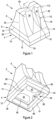
- Figure 1 is a perspective view of a tooth 2 according to an embodiment of the invention.
- the tooth 2 comprises a base 4 and a cap 6.
- the tooth 2 is for a compactor vehicle, specifically a compactor vehicle wheel. In use, the tooth 2 serves to compact, and break up, material.
- the compactor vehicle may be one of a number of different types of compactor vehicle, such as a: landfill, soil or rock compactor vehicle.
- the material which is compacted and/or broken up by the tooth 2, in use may therefore include landfill waste, soil (e.g. dirt) and/or rocks (e.g. aggregate).
- the tooth 2 is mounted to a wheel of a landfill compactor vehicle, and is used to compact, and break up, landfill waste.
- the tooth 2 is manufactured in a two-part casting process, which may be referred to as a twin-shot casting process.
- the base 4 is initially cast using a (first) molten metal material and allowed to cool. With the base 4 set (e.g. solidified), the base 4 then forms part of a mould into which a (second) molten metal material, which forms the cap 6, is poured and allowed to set.
- the tooth 2 can therefore be manufactured to have a weldable base 4 and a hard-wearing cap 6 in a single body (with the two parts secured together). This is achieved by manufacturing the base 4 and the cap 6 from two different materials.
- base 4 and cap 6 are interconnected by way of one or more retention features which will be described in connection with later figures (and are shown in, for example, Figures 11 and 12 .)
- the base 4 comprises a body 8.
- the body 8 defines the bulk of the base 4.
- the body 8 defines an underside 10 which, in use, is configured to engage a wheel of the compactor vehicle.
- the underside 10 may be at least partly arcuate. Providing an at least partly arcuate underside 10 is advantageous in providing a more secure fix, or engagement, of the base 4, and so tooth 2, to a wheel (e.g. a drum) of the compactor vehicle.
- the body 8 of the base 4 comprises two portions: first and second portions 12, 14.
- the first portion 12 is a portion which defines the underside 10.
- the second portion 14 extends from the first portion 12.
- the second portion 14 generally tapers so as to define a narrowing cross-section of the base 4.
- the uppermost point of the second portion 14 of the body 8 the base 4 meets the cap 6 at four outer join lines 16, 18 (only two of which are visible in Figure 1 ).
- the join lines 16, 18 define a generally uninterrupted surface between the cap 6 and the base 4, specifically outer surfaces thereof.
- the molten metal material used to manufacture the cap 6 may outwardly overhang the base 4 (e.g. by between around 5 mm to around 7 mm).
- Said overhang may be ground, or fettled, back to leave the generally uninterrupted, or flush, surface and to define the outer join lines 16, 18. This has been found to improve the casting process by reducing chillback (e.g. reducing the formation of cracks, proximate the join lines 16, 18, owing to the cap 6 material cooling too quickly during casting).
- tooth 2 over prior art teeth, is that the second portion 14 of the body 8 of the base 4 was previously occupied by material used to manufacture the cap 6.
- the base 4 has therefore effectively increased in height. This reduces the amount of comparatively expensive molten metal material used to cast the cap.
- the first portion 12 further comprises chamfers 24, 26 which facilitate the welding of the base 4 to the wheel of the compactor vehicle.
- the chamfers 24, 26 extend across an entire width of the base 4.
- the base 4, and so tooth 2 may only be welded to the wheel at the chamfers 24, 26 (e.g. at two edges of the underside 10).
- the base 4 may be welded to the wheel at all four edges of the underside 10 (e.g. at chamfers 24, 26 and at the edges which extend between the chamfers 24, 26). Attachment at all sides (e.g. so as to form a seal, of sorts, between the underside 10 and the wheel) advantageously reduces the risk of ingress of material (e.g. debris, fluid etc.) underneath the base 4.
- material e.g. debris, fluid etc.
- the cap 6 comprises an outer surface 28 which defines a compaction surface. That is to say, in use, it is the outer surface 28 of the cap 6 which provides a majority of the compacting action, or functionality.
- the outer surface 28 of the cap 6 defines a number of different features including flat faces 30 (only one which is visible in Figure 1 ), arcuate surfaces 34 (only one of which is visible in Figure 1 ) and arcuate recesses 38, 40 (only two of which are visible in Figure 1 ).
- the outer tip 46 refers to an uppermost surface of the tooth 2.
- the outermost tip 46 is M-shaped illustrated embodiment, but other profiles of outer tip 46 are possible. Indeed, a dumbbell-shaped outer tip is shown in Figures 18 and 19 , which will be described later in this document.
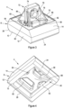
- FIG. 2 a perspective view of the tooth 2 is provided generally from an underside thereof.
- the Figure 2 view shows, more clearly, a cavity 48 which is defined in the underside 10 of the base 4.
- the cavity 48 is a volume which is free of any material. That is to say, the cavity 48 is not occupied by either base 4 material or cap 6 material. Instead, the cavity 48 exists as a free volume within the base 4.
- incorporation of the cavity 48 provides savings in the amount of material required to cast the base 4. Specifically, the amount of a first molten metal material, used to cast the base 4, is reduced. It will therefore be appreciated that there are associated costs, and weight, savings due to the reduction in material which would otherwise be present in place of the cavity 48. The weight savings are particularly advantageous in reducing the loading requirement placed on the transmission of the vehicle (to which the tooth 2 is mounted).
- a further advantage of the cavity 48 is that the thermal inertia of the base 4 is reduced.
- the base 4 can more readily increase in temperature in comparison to if the cavity 48 was filled with material (to define a solid block-like base).
- the base 4 will be cast first, using a first molten metal material which is then allowed to cool (to solidify the base 4).
- the cap 6 is generally cast onto the base 4 by using a second molten metal material.
- the base 4 may therefore form part of the mould which is used to cast the cap 6.
- a further associated advantage is that less heat is required to weld the base 4 of the tooth 2 to the wheel of the compactor vehicle. Owing to the reduced thermal inertia of the base 4, welds have been found to have improved penetration into the base 4 and the wheel. This is owing, at least in part, to less heat being drawn out of the weld, during the welding process, by an otherwise solid base (which could act as a heat sink of sorts). Put another way, it is walls of the base, forming a peripheral edge of the underside 10, which are welded, rather than an otherwise solid cuboidal base. Cracking associated with the weld(s) may therefore be alleviated.
- FIG. 2 Also visible in Figure 2 are outer ends 50, 52, 54, 56 of projections forming part of the cap 6. These projections are more clearly visible in Figures 11 to 17 (labelled 49, 51, 53, 55) and will be described in detail later in this document. Briefly, the projections of the cap 6 are formed when the second molten metal material is cast onto the base 4. The projections are formed by virtue of the molten material flowing through the recesses 58, 60, 62, 64 defined in the base 4. The recesses 58, 60, 62, 64 are more clearly visible in Figures 5 and 6 .
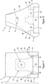
- Figure 3 a perspective view, generally from above, of the base 4 is provided in isolation. Figure 3 more clearly shows a number of features of the base 4 which are used to interconnect the cap 6 to the base 4.
- the base 4 further comprises a lip 70.
- the lip 70 extends around a peripheral edge of the cap-facing side 68.
- the lip 70 may be said to project from the cap-facing side 68.
- the lip 70 projects by around 3 mm (upwardly) from the cap-facing side 68.
- the lip 70 preferably projects by between around 1 mm and around 5 mm.
- the lip 70 is around 3 mm in thickness when viewed in plan (i.e. in width or depth).
- the lip 70 is preferably between around 1 mm and around 5 mm in thickness when viewed in plan.
- the base 4 further comprises an attachment portion 72.
- the attachment portion 72 extends from a cap-facing side 68.
- the attachment portion 72 defines an uppermost point of the base 4 at an outer tip 74 of the attachment portion 72.
- Attachment portion 72 facilitates attachment of the cap to the base 4.
- the attachment portion 72 is generally cuboidal and maybe described as tab-shaped.
- the attachment portion 72 defines a retention feature in the form of an aperture 76.
- the aperture 76 is a feature which molten metal material, of the cap, flows through when the cap is cast onto the base 4.
- the features interlock to secure the cap to the base 4 (as shown in, for example, Figures 11 and 12 ).
- the aperture 76 is a generally arcuate aperture.
- arcuate aperture is intended to mean that less than around 30%, preferably less than around 25% or 20%, of a perimeter of the aperture 76 is defined by linear edges. Instead, the majority of the perimeter of the aperture 76 is defined by arcuate edges.
- incorporating a generally arcuate aperture 76 reduces any comparatively sharp fillets which could otherwise lead to cracks propagating in the attachment portion 72 as part of the manufacturing (casting) process.
- the land of material 78 refers to a solid block of material.
- the presence of the land 78 of material provides structural reinforcement, and robustness, to the base 4 despite the incorporation of the aperture 76.
- the aperture 76 may be said to be offset from the cap-facing side 68 by the land 78 of material.
- buttresses 80, 82, 86 extend between the attachment portion 72 and the cap-facing side 68.
- the buttresses 80, 82, 86 are supporting projections of sorts which extend in a generally diagonal direction when viewed in plan (see, for example, Figure 5 ).
- the buttresses 80, 82, 86 are generally triangular projections.
- the presence of the buttresses 80, 82, 86 reduces the risk of distortion occurring to the attachment portion 72, particularly between the attachment portion 72 and the cap-facing side 68. This is of particular importance where the attachment portion 72 is used to secure the cap to the base 64.
- the presence of the buttresses 80, 82, 86 also reduces the risk of torsional distortion, or twisting, of the attachment portion 72 about the cap-facing side 68.
- each of the buttresses 80, 82, 86 extends between a respective two recesses 58, 60, 64. Again, this is more clearly visible in Figure 5 .
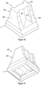
- Figure 4 a perspective view of the base 4 is provided shown generally from the underside. Figure 4 thus shows the cavity 48 defined in the underside 10 of the base 4.
- Figure 4 shows how the recesses 58, 60, 62, 64 open out into the cavity 48. Put another way, the recesses 58, 60, 62, 64 extend to the recess 48. When Figure 4 is viewed in combination with Figure 3 it will be appreciated that each of the recesses 58, 60, 62, 64 extends between the cap-facing side 68 and the recess 48. Figure 4 also illustrates how lower ends of the recesses 58, 60, 62, 64 have filleted edges like that described in connection with the upper edges in connection with Figure 3 .
- Figure 4 also shows a generally X-shaped geometry which defines an uppermost point of the recess 48.
- Said X-shaped geometry is defined at least partly by a surface 88 provided between the cavity 48 and the aperture 76 (in the attachment portion 72).
- the recess 48 may therefore be said to extend between the surface 88 and the underside 10.
- the surface 88 defines an uppermost point of the cavity 48.
- Figure 4 also shows the first and second portions 12, 14 of the body 8 of the base 4.
- Chamfers 24, 26 defined in the front and rear edges of the first portion 12 are also visible in Figure 4 .
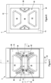
- FIG. 5 a plan view of the base 4 is provided.
- FIG. 5 more clearly shows the arrangement of the four recesses 58, 60, 62, 64 extending between the cap-facing side 68 and the recess (provided beneath the indicated recesses in Figure 5 ).
- Each of the recesses 58, 60, 62, 64 are generally trapezoidal in that they have one pair of parallel sides. The shapes of the recesses 58, 60, 62, 64 may otherwise be described as dovetail-like or tapering.
- Third and fourth recesses 62, 64 are smaller in cross-section than the first and second recesses 58, 60.
- the recesses can be grouped into two pairs of recesses 58, 60 and 62, 64. Recesses belonging to a given pair may each be said to generally oppose one another in that they mirror each other across a central plane of the base 4. Two such planes are indicated schematically in Figure 5 as 90, 92.
- the plane 90 bisects the base 4 between front and rear sides thereof.
- the first plane 90 may therefore be said to define a mid-point of a depth of the tooth.
- First and second recesses 58, 60 are provided equidistant from, and opposing one another about, the first plane 90.
- the second plane 92 bisects the base 4 between left and right sides thereof.
- the second plane 92 may therefore be said to define a mid-point of a width of the base 4.
- Third and fourth recesses 62, 64 are provided equidistant from, and oppose one another about, the second plane 92.
- the base 4 has two planes of symmetry about both the first and second planes 90, 92. More uniform cooling, and being able to insert the base 4 into the mould in multiple orientations, are benefits stemming from the symmetry of the base 4.
- the symmetry also provides the possibility of being able to rotate the cap, relative to the base 4, when the tooth is manufactured, to provide a 'lateral' tooth.
- Figure 5 illustrates each of the buttresses 80, 82, 84, 86 extending between the attachment portion 72 and the cap-facing side 68.
- Each of the buttresses 80, 82, 84, 86 generally extends from a corner of the cuboidal attachment portion 72 when viewed from above.
- Each of the buttresses 80, 82, 84, 86 also extends in a direction between a respective two recesses 58, 60, 62, 64.
- the first buttress 80 extends between the first recess 58 and fourth recess 64.
- the buttresses 80, 82, 84, 86 extend generally diagonally across the cap-facing surface 68.
- the base 4 has an aspect ratio (i.e. a ratio of width to depth) of around 0.8 when viewed in plan
- the base 4 preferably has an aspect ratio of between around 0.6 and around 1 when viewed in plan.
- the base 4 is preferably generally square.
- Figure 6 a view of the base 4 from underneath is provided.
- Figure 6 shows the underside 10 generally defined by the peripheral edge 66 which extends around the cavity 48.
- the cavity 48 can therefore be said to be defined by the peripheral edge 66 and/or the underside 10.
- Figure 6 shows the layout of the recesses 58, 60, 62, 64 from underneath.
- the recesses 58, 60, 62, 64 may be collectively referred to as an array, or arrangement, of recesses.
- the generally X-shaped surface 88, which defines an upper limit of the recess 48, is also shown.
- Chamfers 24, 26 are also visible in Figure 6 .
- the outer sides 94, 96 of the first portion 12 are generally planar and extend in a vertical direction. Outer sides 98, 100 of the second portion 14 are also planar but incorporate a shallow draft, of around 2.5°, away from the vertical.
- a vertical height of the first portion 12 is around 35mm in the illustrated embodiment.
- the vertical height of the first portion 12 is preferably between around 30 mm and around 45 mm.
- a vertical height of the second portion 14 is also around 35mm in the illustrated embodiment.
- the vertical height of the second portion 14 is preferably between around 30 mm and around 45 mm.
- the combined heights of the first and second portions 12, 14, and so an overall height of the body 8, is therefore around 70mm in the illustrated embodiment.
- the combined heights of the first and second portions 12, 14, and so an overall height of the body 8, is preferably between around 60 mm and around 90 mm.
- a range of other dimensions, and geometries, may otherwise be used.
- the illustrated tooth 2 in comparison to existing teeth, is the presence of the second portion 14 of the body 8 of the base 4.
- increasing the height of the body 8 of the base 4, by incorporating the second portion 14, avoids using the (comparatively expensive) second molten metal material, used to manufacture the cap, in regions which generally experience low wear in use. It has been found that below around 70 mm, of an overall height of the tooth 2, the wear is considerably lower than in the region above it.
- the illustrated tooth 2 therefore provides a desirable balance of cost saving and durability by increasing the height of the body 8 of the base 4.
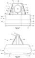
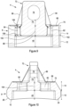
- Figure 8 is a side view of the base 4.
- Figure 8 shows the arcuate nature of the underside 10, or specifically a portion thereof.
- the underside 10 being at least partly arcuate is advantageous in providing a more secure engagement of the base 4, and so the overall tooth, to a wheel of the compactor vehicle.
- An at least partly arcuate underside 10 therefore provides an improved conformance of the underside 10 of the base 4 to the wheel of the compactor vehicle.
- the radius of curvature of the underside 10 is around 750mm. However, and as mentioned above, other dimensions may otherwise be used.
- Figure 8 also shows first and fourth buttresses 80, 86 extending from the attachment portion 72 to the body 8 to the base 4. Like in Figure 7 , the outer tip 74 of the attachment portion defines an uppermost point, or outer tip 74, of the base 4.
- a depth 75 of the base 4 is around 200 mm in the illustrated embodiment.
- the depth 75 is preferably between around 100 mm and around 300 mm.
- the aforementioned depth dimensions also apply to the tooth more generally (i.e. the depth of the tooth is around 160 mm in the illustrated embodiment).
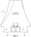
- FIG. 9 a cross-section front view of the base 4 is provided as indicated by the cross-section marker 91 shown in Figure 5 .
- the cross-section front view indicates the relative depths of various internal features of the base 4 previously introduced in this document.
- Figure 9 shows the body 8 of the base 4 comprising the first and second portions 12, 14.
- Attachment portion 72 is shown extending from the cap-facing side 68, the attachment portion 72 defining the generally arcuate aperture 76 therethrough.
- Third and fourth buttresses 84, 86 extend between the attachment portion 72 and the cap-facing side 68.
- the lip 70 extends around a periphery of the cap-facing side 68.
- the land 68 of material provided between the cap-facing side 68 and the aperture 76 is also indicated, along with the vertical height of the same.
- Third and fourth recesses 62, 64 which extend between the cap-facing side 68 and the cavity 48, are also shown.
- a vertical height, depth or extent, of the third and fourth recesses 62, 64 is labelled 104 in Figure 9 .
- the vertical height 104 of the third and fourth recesses 62, 64 is substantially the same as the vertical height of the recesses 58, 60 (not shown in Figure 9 ).
- a height, or depth, of the recesses is defined between the cap-facing side 68 and the surface 88.
- the recesses 62, 64 open out into the cavity 48.
- a vertical extent of the cavity 48 is also labelled in Figure 9 .
- an indicated plane 102 corresponds with the surface 88, which defines an end point of both the cavity 48 and the recesses 62, 64.
- Figure 9 also indicates the undercut nature of the recesses 62, 64. Described only in connection with the fourth recess 64, but equally applicable to the third recess 62 (and first and second recesses 58, 60), the fourth recess 64 has a narrowest width 106 and a width 108 at a lowermost point of the recess 64. It will be appreciated that along the depth of the recess 64, moving from the narrowest point 106 towards the lowermost end width 108, the recess 64 generally increases in width. This may otherwise be described as the generally undercut feature. This is particularly evident at the width 108 defined at the lowermost point of the recess 64.
- the second molten metal material of the cap When molten metal material of the cap is poured onto the cap-facing side 68 of the base 4, as part of the manufacturing process, the second molten metal material runs along the cap-facing side 68 and down into the recesses 62, 64.
- the second molten metal material is substantially prevented from entering the cavity 48 and its flow is therefore limited to approximately the plane indicated by 102 in Figure 9 (i.e. in line with the surface 88).
- the second molten metal material, which goes on to form the cap therefore only extends down to a lowermost point of the recesses 62, 64, as indicated by a lowermost point of the height indicator 104.
- the second molten metal material therefore entirely fills the recesses 62, 64, including at both narrowest, and end, points 106, 108.
- the cap and base 4, specifically projections (not shown in Figure 9 ) and the recesses 62, 64 thereof, thus define retention features which secure the base to the cap.
- the attachment portion 72, and so aperture 76 may be omitted.
- the recesses 62, 64 still define retention features which, after the cap has been cast onto the base 4, interlock the cap with the base 4. Any attempt at separating the cap from the base is substantially prevented by the interference of cap material with the narrowing recesses 62, 64. It will be appreciated that once the second molten metal material is poured onto the cap-facing side 68, and flows into the recesses 62, 64, the resulting cap material generally conforms, or corresponds to, the geometry of the recesses 62, 64 (and 58, 60, not shown in Figure 9 ). This is owing to the fact that the base 4 forms at least part of a mould used to cast the cap, and so overall tooth.
- Figure 9 also illustrates how the cavity 48 extends through a majority of the first portion 12 of the base 4.
- the plane 102 corresponding to the surface 88 and so an uppermost point of the cavity 48, the plane 102 lies at a lower position than a lowermost point of the second portion 14.
- the illustrated cavity 48 does not extend through an entirety of the first portion 12, but in some embodiments the cavity may extend through an entirety of the first portion 12. Similarly, in some embodiments the cavity may extend through an entirety of the first portion 12, and at least part of the second portion 14.
- FIG. 10 a cross-section side view of the base 4 is provided as indicated by the cross-section marking labelled 93 in Figure 5 .
- Figure 10 more clearly shows the arcuate nature of at least part of the underside 10 of the base 4.
- the attachment portion 72 is again shown extending from the cap-facing side 68, and defining the generally arcuate aperture 76 therethrough.
- the land of material 78 provided between the cap-facing side 68 and the aperture 76 is also labelled.
- the lip 70 extends around the periphery of the cap-facing side 68.
- the land of material 78 is around 20 mm in height in the illustrated embodiment, and is preferably between around 10 mm and 30 mm.
- First and second recesses 58, 60 are visible in Figure 10 .
- the first and second recesses 58, 60 generally increase in cross-section moving from an uppermost point of the recesses towards a lowermost point of the recesses.
- the recesses 58, 60 are generally undercut in that their cross-section towards a lowermost point of the recesses is greater than a cross-section at an uppermost point.
- each of the recesses 58, 60 and corresponding projections of the cap (not shown in Figure 10 ), define retention features which interlock with one another to secure the cap to the base 4.
- Figure 11 is a front cross-section view of the tooth 2 taken about a cross-section line as indicated by the cross-section markers 110 in Figure 1 .
- the tooth 2 is shown in an assembled state and with both the base 4 and the cap 6 present. Retention features of the base 4 and the cap 6, as will be described in detail below, interlock with one another to interlock the base 4 to the cap 6.
- Figure 11 indicates how the molten metal material used to cast the cap 6 generally flows over the cap-facing side 68 of the base 4. Furthermore, the molten metal material flows into the third and fourth recesses 62, 64 (and first and second recesses - not shown in Figure 11 ).
- a plurality of projections 53, 55 are defined in the cap 6.
- the projections 49, 51, 53, 55 are also shown in Figures 13 and 14 , whereat the cap 6 is shown in isolation of the base 4.
- third and fourth projections 53, 55 extend through third and fourth recesses 62, 64.
- the volumes, e.g. geometries, of the third and fourth projections 53, 55 generally match those of the third and fourth recesses 62, 64. This is to be expected given that the recesses 62, 64 effectively form part of the mould used to cast the cap 6.
- Figure 11 illustrates how the outer ends 54, 56 of the third and fourth projections 53, 55 splay outwardly relative to a body of the projections 53, 55. Put another way, the projections 53, 55 extend outwardly at outer ends 54, 56 thereof. This provides an anchoring functionality in that the projected cap 6 is thus securely interlocked with, and secured to, the base 4.
- the outer ends 54, 56 of the projections 53, 55 are generally flush with the surface 88 which also defines the uppermost surface of the cavity 48.
- the molten metal material used to cast the cap 6 only extends down to the point where the outer ends 54, 56 of the projections 53, 55 are defined.
- Substantially no molten metal material, used to manufacture the cap 6, thus enters the cavity 48.
- This effect may be achieved by sealing, or blocking, the cavity 48 whilst the molten metal material, used to manufacture the cap 6, is poured.
- a blocking element may be used as a way of preventing the molten metal material flowing into the cavity 48.
- the blocking element may also advantageously define a lowermost surface of the recesses 62, 64 during the moulding process.
- Figure 12 shows the portion 114 of material of the cap 6 which extends through the aperture 76.
- the attachment portion 72 appears disjointed owing to the presence of the aperture 76.
- the land 78 of material between the aperture 76 and the cap-facing side 68 is also more clearly visible in Figure 12 .
Landscapes
- Engineering & Computer Science (AREA)
- Structural Engineering (AREA)
- Life Sciences & Earth Sciences (AREA)
- Mechanical Engineering (AREA)
- Mining & Mineral Resources (AREA)
- Soil Sciences (AREA)
- Environmental & Geological Engineering (AREA)
- General Life Sciences & Earth Sciences (AREA)
- Agronomy & Crop Science (AREA)
- Paleontology (AREA)
- Civil Engineering (AREA)
- General Engineering & Computer Science (AREA)
- Vehicle Body Suspensions (AREA)
- Molds, Cores, And Manufacturing Methods Thereof (AREA)
- Connection Of Plates (AREA)
- Devices For Conveying Motion By Means Of Endless Flexible Members (AREA)
- Cosmetics (AREA)
Claims (15)
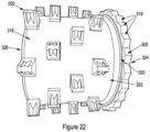
- Zahn (2) für ein Verdichterfahrzeug, wobei der Zahn eine Basis (4) und eine Kappe (6) umfasst;
wobei die Basis Folgendes umfasst:einen Körper (8), der eine Unterseite (10) definiert, die dazu konfiguriert ist, in ein Rad (316) des Verdichterfahrzeugs einzugreifen, und eine entgegengesetzte, der Kappe zugewandte Seite (68); undein Rückhaltemerkmal (58, 60, 62, 64, 72), in dem Material der Kappe aufgenommen ist;wobei die Kappe Folgendes umfasst:eine Außenoberfläche (28), die eine Verdichtungsoberfläche definiert; undeine Rückhaltemerkmal (49, 51, 53, 55, 114);wobei sich die Rückhaltemerkmale der Basis und der Kappe gegenseitig verriegeln, um die Kappe an der Basis zu fixieren und zu verhindern, dass sich die Kappe von der Basis trennt;dadurch gekennzeichnet, dass ein Hohlraum (48) in der Unterseite der Basis definiert ist. - Zahn (2) nach Anspruch 1, wobei der Hohlraum (48) durch eine umfängliche Kante (66), die sich um die Unterseite (10) der Basis (4) erstreckt, gebunden ist; und/oder
wobei der Hohlraum (48) allgemein quaderförmig ist. - Zahn (2) nach Anspruch 1 oder Anspruch 2, wobei der Körper (8) Folgendes umfasst:einen ersten Abschnitt (12), der mindestens die Unterseite (10) definiert; undeinen zweiten Abschnitt (14), der sich von dem ersten Abschnitt erstreckt und allgemein in einer Richtung von der Unterseite weg verjüngt; optionalwobei sich der Hohlraum (48) durch mindestens einen Großteil des ersten Abschnitts der Basis erstreckt.
- Zahn (2) nach einem der vorstehenden Ansprüche, wobei die Basis (4) ferner mindestens eine oder mehrere Vertiefungen (58, 60, 62, 64) umfasst, wobei sich die eine oder mehreren Vertiefungen zwischen dem Hohlraum (48) und der der Kappe zugewandten Seite (68) erstrecken; optional
wobei die eine oder die mehreren Vertiefungen allgemein trapezförmig sind. - Zahn (2) nach einem der vorstehenden Ansprüche, wobei die Basis (4) ferner einen Anbringungsabschnitt (72) umfasst, der von der der Kappe zugewandten Seite (68) vorragt.
- Zahn (2) nach Anspruch 5, wobei der Anbringungsabschnitt (72) ein Rückhaltemerkmal der Basis definiert, optional das Rückhaltemerkmal der Basis (4).
- Zahn (2) nach Anspruch 6, wobei das Rückhaltemerkmal der Basis (4) eine Öffnung (76) umfasst, die sich durch den Anbringungsabschnitt (72) erstreckt; optional
wobei ein Materialsteg (78) zwischen der der Kappe zugewandten Seite (68) und einem untersten Punkt der Öffnung (76) definiert ist. - Zahn (2) nach Anspruch 7, wobei die Öffnung (76) eine allgemein bogenförmige Öffnung ist.
- Zahn (2) nach einem der vorstehenden Ansprüche, wobei sich ein oder mehrere Stützpfeiler (80, 82, 84, 86) zwischen dem Anbringungsabschnitt (72) und der der Kappe zugewandten Seite (68) erstrecken.
- Zahn (2) nach einem der vorstehenden Ansprüche, wobei die Basis (4) eine Lippe (70) umfasst, die sich um eine umfängliche Kante der der Kappe zugewandten Seite (68) erstreckt.
- Verfahren zum Herstellen eines Zahns (2) nach einem der vorstehenden Ansprüche, wobei das Verfahren Folgendes umfasst:Gießen der Basis (4) unter Verwendung eines ersten geschmolzenen Metallmaterials;Gießen der Kappe (6) auf mindestens die der Kappe zugewandte Seite (68) der Basis unter Verwendung eines zweiten geschmolzenen Metallmaterials;wobei sich die Rückhaltemerkmale (49, 51, 53, 55, 58, 60, 62, 64, 72, 114) der Basis und der Kappe gegenseitig verriegeln, um die Kappe an der Basis zu befestigen, während das zweite geschmolzene Material mindestens teilweise geschmolzen ist; undwobei das zweite geschmolzene Metallmaterial im Wesentlichen daran gehindert wird, in den Hohlraum (48) einzutreten.
- Verfahren nach Anspruch 11, wobei das zweite geschmolzene Metallmaterial im Wesentlichen durch ein blockierendes Element, wie ein Muster oder einen Kern, daran gehindert wird, in den Hohlraum (48) einzutreten.
- Verfahren nach Anspruch 11 oder Anspruch 12, wenn sie direkt oder indirekt von Anspruch 4 abhängig sind, wobei das zweite geschmolzene Metallmaterial durch die eine oder mehreren Vertiefungen (58, 60, 62, 64) fließt, um die Kappe (6) an der Basis (4) zu befestigen.
- Verfahren nach einem der Ansprüche 11 bis 13, direkt oder indirekt abhängig von Anspruch 7, wobei das zweite geschmolzene Metallmaterial durch die Öffnung (76) des Anbringungsabschnitts (72) fließt, um die Kappe (6) an der Basis (4) zu befestigen.
- Verdichterfahrzeug, das ein Rad (316) umfasst, wobei ein oder mehrere der Zähne (2) nach einem der Ansprüche 1 bis 10 an dem Rad befestigt sind.
Applications Claiming Priority (2)
| Application Number | Priority Date | Filing Date | Title |
|---|---|---|---|
| US17/243,377 US11268251B1 (en) | 2021-04-28 | 2021-04-28 | Tooth for compactor vehicle and associated method |
| PCT/GB2022/051061 WO2022229627A1 (en) | 2021-04-28 | 2022-04-27 | Tooth and associated method |
Publications (3)
| Publication Number | Publication Date |
|---|---|
| EP4330053A1 EP4330053A1 (de) | 2024-03-06 |
| EP4330053B1 true EP4330053B1 (de) | 2025-06-25 |
| EP4330053C0 EP4330053C0 (de) | 2025-06-25 |
Family
ID=80473309
Family Applications (1)
| Application Number | Title | Priority Date | Filing Date |
|---|---|---|---|
| EP22721830.2A Active EP4330053B1 (de) | 2021-04-28 | 2022-04-27 | Zahn und zugehöriges verfahren |
Country Status (7)
| Country | Link |
|---|---|
| US (2) | US11268251B1 (de) |
| EP (1) | EP4330053B1 (de) |
| CN (1) | CN117529411A (de) |
| AU (1) | AU2022264961B2 (de) |
| CA (1) | CA3217094A1 (de) |
| ES (1) | ES3037339T3 (de) |
| WO (1) | WO2022229627A1 (de) |
Families Citing this family (4)
| Publication number | Priority date | Publication date | Assignee | Title |
|---|---|---|---|---|
| US11268251B1 (en) * | 2021-04-28 | 2022-03-08 | Bernard Mccartney Limited | Tooth for compactor vehicle and associated method |
| USD1107078S1 (en) * | 2024-06-21 | 2025-12-23 | Caterpillar Inc. | Cutting edge bit for a motor grader |
| USD1107761S1 (en) * | 2024-06-21 | 2025-12-30 | Caterpillar Inc. | Cutting edge bit for a motor grader |
| CN121024001B (zh) * | 2025-10-31 | 2026-01-27 | 四川路航建设工程有限责任公司 | 一种水利工程施工用护坡维护装置 |
Citations (1)
| Publication number | Priority date | Publication date | Assignee | Title |
|---|---|---|---|---|
| US3274908A (en) * | 1964-07-22 | 1966-09-27 | Caterpillar Tractor Co | Tamping device |
Family Cites Families (12)
| Publication number | Priority date | Publication date | Assignee | Title |
|---|---|---|---|---|
| US4919566A (en) * | 1984-08-13 | 1990-04-24 | Caron Compactor Co. | Fill and compaction roller using readily replaceable cleat assemblies |
| US4668122A (en) * | 1985-11-20 | 1987-05-26 | Rexworks Inc. | Two bolt taper cleat |
| GB2345036B (en) * | 1998-12-24 | 2002-07-10 | Bernard Mccartney Ltd | Vehicle wheel tooth |
| US6682262B2 (en) * | 2000-05-05 | 2004-01-27 | Caron Compactor Company | Fill and compaction roller using replaceable cleat assemblies with extended service life |
| US7108452B2 (en) * | 2000-05-05 | 2006-09-19 | Caron James O | Fill and compaction roller using replaceable cleat assemblies with extended service life |
| US6712551B2 (en) | 2001-11-27 | 2004-03-30 | Caterpillar Inc | Compactor tooth |
| US6991401B1 (en) * | 2005-04-05 | 2006-01-31 | Caron Compactor Company | Compactor wheel with trash exclusion properties |
| US8449218B2 (en) * | 2010-06-30 | 2013-05-28 | Caterpillar Inc. | Land fill compactor wheel tip assembly |
| USD729852S1 (en) * | 2011-07-18 | 2015-05-19 | Terra Compactor Wheel Corp. | Compaction cleat assembly |
| US8696239B2 (en) | 2011-08-24 | 2014-04-15 | Terra Compactor Wheel Corp. | Full metal jacket compaction wheel cleat and method of manufacturing thereof |
| GB2565073B (en) * | 2017-07-31 | 2021-10-13 | Bernard Mccartney Ltd | Compactor tooth, base therefor and related method |
| US11268251B1 (en) * | 2021-04-28 | 2022-03-08 | Bernard Mccartney Limited | Tooth for compactor vehicle and associated method |
-
2021
- 2021-04-28 US US17/243,377 patent/US11268251B1/en active Active
-
2022
- 2022-02-23 US US17/678,921 patent/US11828036B2/en active Active
- 2022-04-27 ES ES22721830T patent/ES3037339T3/es active Active
- 2022-04-27 AU AU2022264961A patent/AU2022264961B2/en active Active
- 2022-04-27 EP EP22721830.2A patent/EP4330053B1/de active Active
- 2022-04-27 CN CN202280040471.8A patent/CN117529411A/zh active Pending
- 2022-04-27 WO PCT/GB2022/051061 patent/WO2022229627A1/en not_active Ceased
- 2022-04-27 CA CA3217094A patent/CA3217094A1/en active Pending
Patent Citations (1)
| Publication number | Priority date | Publication date | Assignee | Title |
|---|---|---|---|---|
| US3274908A (en) * | 1964-07-22 | 1966-09-27 | Caterpillar Tractor Co | Tamping device |
Also Published As
| Publication number | Publication date |
|---|---|
| ES3037339T3 (en) | 2025-10-01 |
| CA3217094A1 (en) | 2022-11-03 |
| CN117529411A (zh) | 2024-02-06 |
| EP4330053A1 (de) | 2024-03-06 |
| US11268251B1 (en) | 2022-03-08 |
| AU2022264961B2 (en) | 2025-02-27 |
| US20220349141A1 (en) | 2022-11-03 |
| EP4330053C0 (de) | 2025-06-25 |
| US11828036B2 (en) | 2023-11-28 |
| AU2022264961A1 (en) | 2023-12-07 |
| WO2022229627A1 (en) | 2022-11-03 |
Similar Documents
| Publication | Publication Date | Title |
|---|---|---|
| EP4330053B1 (de) | Zahn und zugehöriges verfahren | |
| EP2588672B1 (de) | Radspitzenanordnung für einen müllverdichter | |
| US11208781B2 (en) | Compactor tooth base having a trench extending around a core | |
| US8496402B2 (en) | Paddle style land fill compactor wheel tip | |
| US6632045B1 (en) | Vehicle wheel tooth | |
| CN105228773B (zh) | 铸造方法 | |
| JPH0634824Y2 (ja) | 破砕機の歯板 | |
| US8877347B2 (en) | Wear element, and component provided therewith | |
| CA2908359C (en) | Wear component for compactor wheel | |
| CN218780479U (zh) | 一种切割环及混凝土泵送设备 | |
| JP7529051B2 (ja) | 鋼管ソイルセメント合成杭、鋼管杭、及び鋼管ソイルセメント合成杭の施工方法 | |
| JPH0529223Y2 (de) | ||
| TWM293279U (en) | Earth removing device of roadway scraper |
Legal Events
| Date | Code | Title | Description |
|---|---|---|---|
| STAA | Information on the status of an ep patent application or granted ep patent |
Free format text: STATUS: UNKNOWN |
|
| STAA | Information on the status of an ep patent application or granted ep patent |
Free format text: STATUS: THE INTERNATIONAL PUBLICATION HAS BEEN MADE |
|
| PUAI | Public reference made under article 153(3) epc to a published international application that has entered the european phase |
Free format text: ORIGINAL CODE: 0009012 |
|
| STAA | Information on the status of an ep patent application or granted ep patent |
Free format text: STATUS: REQUEST FOR EXAMINATION WAS MADE |
|
| 17P | Request for examination filed |
Effective date: 20231123 |
|
| AK | Designated contracting states |
Kind code of ref document: A1 Designated state(s): AL AT BE BG CH CY CZ DE DK EE ES FI FR GB GR HR HU IE IS IT LI LT LU LV MC MK MT NL NO PL PT RO RS SE SI SK SM TR |
|
| DAV | Request for validation of the european patent (deleted) | ||
| DAX | Request for extension of the european patent (deleted) | ||
| STAA | Information on the status of an ep patent application or granted ep patent |
Free format text: STATUS: EXAMINATION IS IN PROGRESS |
|
| 17Q | First examination report despatched |
Effective date: 20240911 |
|
| GRAP | Despatch of communication of intention to grant a patent |
Free format text: ORIGINAL CODE: EPIDOSNIGR1 |
|
| STAA | Information on the status of an ep patent application or granted ep patent |
Free format text: STATUS: GRANT OF PATENT IS INTENDED |
|
| INTG | Intention to grant announced |
Effective date: 20250124 |
|
| GRAS | Grant fee paid |
Free format text: ORIGINAL CODE: EPIDOSNIGR3 |
|
| GRAA | (expected) grant |
Free format text: ORIGINAL CODE: 0009210 |
|
| STAA | Information on the status of an ep patent application or granted ep patent |
Free format text: STATUS: THE PATENT HAS BEEN GRANTED |
|
| AK | Designated contracting states |
Kind code of ref document: B1 Designated state(s): AL AT BE BG CH CY CZ DE DK EE ES FI FR GB GR HR HU IE IS IT LI LT LU LV MC MK MT NL NO PL PT RO RS SE SI SK SM TR |
|
| REG | Reference to a national code |
Ref country code: GB Ref legal event code: FG4D |
|
| REG | Reference to a national code |
Ref country code: CH Ref legal event code: EP |
|
| REG | Reference to a national code |
Ref country code: CH Ref legal event code: EP |
|
| REG | Reference to a national code |
Ref country code: IE Ref legal event code: FG4D |
|
| REG | Reference to a national code |
Ref country code: DE Ref legal event code: R096 Ref document number: 602022016447 Country of ref document: DE |
|
| U01 | Request for unitary effect filed |
Effective date: 20250724 |
|
| U07 | Unitary effect registered |
Designated state(s): AT BE BG DE DK EE FI FR IT LT LU LV MT NL PT RO SE SI Effective date: 20250730 |
|
| REG | Reference to a national code |
Ref country code: ES Ref legal event code: FG2A Ref document number: 3037339 Country of ref document: ES Kind code of ref document: T3 Effective date: 20251001 |
|
| PG25 | Lapsed in a contracting state [announced via postgrant information from national office to epo] |
Ref country code: GR Free format text: LAPSE BECAUSE OF FAILURE TO SUBMIT A TRANSLATION OF THE DESCRIPTION OR TO PAY THE FEE WITHIN THE PRESCRIBED TIME-LIMIT Effective date: 20250926 Ref country code: NO Free format text: LAPSE BECAUSE OF FAILURE TO SUBMIT A TRANSLATION OF THE DESCRIPTION OR TO PAY THE FEE WITHIN THE PRESCRIBED TIME-LIMIT Effective date: 20250925 |
|
| PG25 | Lapsed in a contracting state [announced via postgrant information from national office to epo] |
Ref country code: HR Free format text: LAPSE BECAUSE OF FAILURE TO SUBMIT A TRANSLATION OF THE DESCRIPTION OR TO PAY THE FEE WITHIN THE PRESCRIBED TIME-LIMIT Effective date: 20250625 |
|
| PG25 | Lapsed in a contracting state [announced via postgrant information from national office to epo] |
Ref country code: RS Free format text: LAPSE BECAUSE OF FAILURE TO SUBMIT A TRANSLATION OF THE DESCRIPTION OR TO PAY THE FEE WITHIN THE PRESCRIBED TIME-LIMIT Effective date: 20250925 |
|
| PG25 | Lapsed in a contracting state [announced via postgrant information from national office to epo] |
Ref country code: IS Free format text: LAPSE BECAUSE OF FAILURE TO SUBMIT A TRANSLATION OF THE DESCRIPTION OR TO PAY THE FEE WITHIN THE PRESCRIBED TIME-LIMIT Effective date: 20251025 |
|
| PG25 | Lapsed in a contracting state [announced via postgrant information from national office to epo] |
Ref country code: SM Free format text: LAPSE BECAUSE OF FAILURE TO SUBMIT A TRANSLATION OF THE DESCRIPTION OR TO PAY THE FEE WITHIN THE PRESCRIBED TIME-LIMIT Effective date: 20250625 |
|
| PG25 | Lapsed in a contracting state [announced via postgrant information from national office to epo] |
Ref country code: CZ Free format text: LAPSE BECAUSE OF FAILURE TO SUBMIT A TRANSLATION OF THE DESCRIPTION OR TO PAY THE FEE WITHIN THE PRESCRIBED TIME-LIMIT Effective date: 20250625 |
|
| PG25 | Lapsed in a contracting state [announced via postgrant information from national office to epo] |
Ref country code: PL Free format text: LAPSE BECAUSE OF FAILURE TO SUBMIT A TRANSLATION OF THE DESCRIPTION OR TO PAY THE FEE WITHIN THE PRESCRIBED TIME-LIMIT Effective date: 20250625 |
|
| PG25 | Lapsed in a contracting state [announced via postgrant information from national office to epo] |
Ref country code: SK Free format text: LAPSE BECAUSE OF FAILURE TO SUBMIT A TRANSLATION OF THE DESCRIPTION OR TO PAY THE FEE WITHIN THE PRESCRIBED TIME-LIMIT Effective date: 20250625 |
|
| U20 | Renewal fee for the european patent with unitary effect paid |
Year of fee payment: 5 Effective date: 20260205 |