EP4330097B1 - Commande de véhicule basée sur des limites de patinage longitudinal de roue configurées dynamiquement - Google Patents
Commande de véhicule basée sur des limites de patinage longitudinal de roue configurées dynamiquement Download PDFInfo
- Publication number
- EP4330097B1 EP4330097B1 EP21722407.0A EP21722407A EP4330097B1 EP 4330097 B1 EP4330097 B1 EP 4330097B1 EP 21722407 A EP21722407 A EP 21722407A EP 4330097 B1 EP4330097 B1 EP 4330097B1
- Authority
- EP
- European Patent Office
- Prior art keywords
- vehicle
- lim
- wheel slip
- wheel
- msd
- Prior art date
- Legal status (The legal status is an assumption and is not a legal conclusion. Google has not performed a legal analysis and makes no representation as to the accuracy of the status listed.)
- Active
Links
Images




Classifications
-
- B—PERFORMING OPERATIONS; TRANSPORTING
- B60—VEHICLES IN GENERAL
- B60W—CONJOINT CONTROL OF VEHICLE SUB-UNITS OF DIFFERENT TYPE OR DIFFERENT FUNCTION; CONTROL SYSTEMS SPECIALLY ADAPTED FOR HYBRID VEHICLES; ROAD VEHICLE DRIVE CONTROL SYSTEMS FOR PURPOSES NOT RELATED TO THE CONTROL OF A PARTICULAR SUB-UNIT
- B60W30/00—Purposes of road vehicle drive control systems not related to the control of a particular sub-unit, e.g. of systems using conjoint control of vehicle sub-units
- B60W30/02—Control of vehicle driving stability
- B60W30/045—Improving turning performance
-
- B—PERFORMING OPERATIONS; TRANSPORTING
- B60—VEHICLES IN GENERAL
- B60T—VEHICLE BRAKE CONTROL SYSTEMS OR PARTS THEREOF; BRAKE CONTROL SYSTEMS OR PARTS THEREOF, IN GENERAL; ARRANGEMENT OF BRAKING ELEMENTS ON VEHICLES IN GENERAL; PORTABLE DEVICES FOR PREVENTING UNWANTED MOVEMENT OF VEHICLES; VEHICLE MODIFICATIONS TO FACILITATE COOLING OF BRAKES
- B60T8/00—Arrangements for adjusting wheel-braking force to meet varying vehicular or ground-surface conditions, e.g. limiting or varying distribution of braking force
- B60T8/17—Using electrical or electronic regulation means to control braking
- B60T8/1755—Brake regulation specially adapted to control the stability of the vehicle, e.g. taking into account yaw rate or transverse acceleration in a curve
- B60T8/17552—Brake regulation specially adapted to control the stability of the vehicle, e.g. taking into account yaw rate or transverse acceleration in a curve responsive to the tyre sideslip angle or the vehicle body slip angle
-
- B—PERFORMING OPERATIONS; TRANSPORTING
- B60—VEHICLES IN GENERAL
- B60W—CONJOINT CONTROL OF VEHICLE SUB-UNITS OF DIFFERENT TYPE OR DIFFERENT FUNCTION; CONTROL SYSTEMS SPECIALLY ADAPTED FOR HYBRID VEHICLES; ROAD VEHICLE DRIVE CONTROL SYSTEMS FOR PURPOSES NOT RELATED TO THE CONTROL OF A PARTICULAR SUB-UNIT
- B60W30/00—Purposes of road vehicle drive control systems not related to the control of a particular sub-unit, e.g. of systems using conjoint control of vehicle sub-units
- B60W30/18—Propelling the vehicle
- B60W30/18009—Propelling the vehicle related to particular drive situations
- B60W30/18145—Cornering
-
- B—PERFORMING OPERATIONS; TRANSPORTING
- B60—VEHICLES IN GENERAL
- B60T—VEHICLE BRAKE CONTROL SYSTEMS OR PARTS THEREOF; BRAKE CONTROL SYSTEMS OR PARTS THEREOF, IN GENERAL; ARRANGEMENT OF BRAKING ELEMENTS ON VEHICLES IN GENERAL; PORTABLE DEVICES FOR PREVENTING UNWANTED MOVEMENT OF VEHICLES; VEHICLE MODIFICATIONS TO FACILITATE COOLING OF BRAKES
- B60T2201/00—Particular use of vehicle brake systems; Special systems using also the brakes; Special software modules within the brake system controller
- B60T2201/16—Curve braking control, e.g. turn control within ABS control algorithm
-
- B—PERFORMING OPERATIONS; TRANSPORTING
- B60—VEHICLES IN GENERAL
- B60W—CONJOINT CONTROL OF VEHICLE SUB-UNITS OF DIFFERENT TYPE OR DIFFERENT FUNCTION; CONTROL SYSTEMS SPECIALLY ADAPTED FOR HYBRID VEHICLES; ROAD VEHICLE DRIVE CONTROL SYSTEMS FOR PURPOSES NOT RELATED TO THE CONTROL OF A PARTICULAR SUB-UNIT
- B60W50/00—Details of control systems for road vehicle drive control not related to the control of a particular sub-unit, e.g. process diagnostic or vehicle driver interfaces
- B60W2050/0001—Details of the control system
- B60W2050/0002—Automatic control, details of type of controller or control system architecture
- B60W2050/0013—Optimal controllers
-
- B—PERFORMING OPERATIONS; TRANSPORTING
- B60—VEHICLES IN GENERAL
- B60W—CONJOINT CONTROL OF VEHICLE SUB-UNITS OF DIFFERENT TYPE OR DIFFERENT FUNCTION; CONTROL SYSTEMS SPECIALLY ADAPTED FOR HYBRID VEHICLES; ROAD VEHICLE DRIVE CONTROL SYSTEMS FOR PURPOSES NOT RELATED TO THE CONTROL OF A PARTICULAR SUB-UNIT
- B60W50/00—Details of control systems for road vehicle drive control not related to the control of a particular sub-unit, e.g. process diagnostic or vehicle driver interfaces
- B60W2050/0001—Details of the control system
- B60W2050/0002—Automatic control, details of type of controller or control system architecture
- B60W2050/0014—Adaptive controllers
-
- B—PERFORMING OPERATIONS; TRANSPORTING
- B60—VEHICLES IN GENERAL
- B60W—CONJOINT CONTROL OF VEHICLE SUB-UNITS OF DIFFERENT TYPE OR DIFFERENT FUNCTION; CONTROL SYSTEMS SPECIALLY ADAPTED FOR HYBRID VEHICLES; ROAD VEHICLE DRIVE CONTROL SYSTEMS FOR PURPOSES NOT RELATED TO THE CONTROL OF A PARTICULAR SUB-UNIT
- B60W50/00—Details of control systems for road vehicle drive control not related to the control of a particular sub-unit, e.g. process diagnostic or vehicle driver interfaces
- B60W2050/0001—Details of the control system
- B60W2050/0019—Control system elements or transfer functions
- B60W2050/0026—Lookup tables or parameter maps
-
- B—PERFORMING OPERATIONS; TRANSPORTING
- B60—VEHICLES IN GENERAL
- B60W—CONJOINT CONTROL OF VEHICLE SUB-UNITS OF DIFFERENT TYPE OR DIFFERENT FUNCTION; CONTROL SYSTEMS SPECIALLY ADAPTED FOR HYBRID VEHICLES; ROAD VEHICLE DRIVE CONTROL SYSTEMS FOR PURPOSES NOT RELATED TO THE CONTROL OF A PARTICULAR SUB-UNIT
- B60W2300/00—Indexing codes relating to the type of vehicle
- B60W2300/12—Trucks; Load vehicles
- B60W2300/125—Heavy duty trucks
-
- B—PERFORMING OPERATIONS; TRANSPORTING
- B60—VEHICLES IN GENERAL
- B60W—CONJOINT CONTROL OF VEHICLE SUB-UNITS OF DIFFERENT TYPE OR DIFFERENT FUNCTION; CONTROL SYSTEMS SPECIALLY ADAPTED FOR HYBRID VEHICLES; ROAD VEHICLE DRIVE CONTROL SYSTEMS FOR PURPOSES NOT RELATED TO THE CONTROL OF A PARTICULAR SUB-UNIT
- B60W2300/00—Indexing codes relating to the type of vehicle
- B60W2300/14—Tractor-trailers, i.e. combinations of a towing vehicle and one or more towed vehicles, e.g. caravans; Road trains
- B60W2300/147—Road trains
-
- B—PERFORMING OPERATIONS; TRANSPORTING
- B60—VEHICLES IN GENERAL
- B60W—CONJOINT CONTROL OF VEHICLE SUB-UNITS OF DIFFERENT TYPE OR DIFFERENT FUNCTION; CONTROL SYSTEMS SPECIALLY ADAPTED FOR HYBRID VEHICLES; ROAD VEHICLE DRIVE CONTROL SYSTEMS FOR PURPOSES NOT RELATED TO THE CONTROL OF A PARTICULAR SUB-UNIT
- B60W2552/00—Input parameters relating to infrastructure
- B60W2552/30—Road curve radius
-
- B—PERFORMING OPERATIONS; TRANSPORTING
- B60—VEHICLES IN GENERAL
- B60W—CONJOINT CONTROL OF VEHICLE SUB-UNITS OF DIFFERENT TYPE OR DIFFERENT FUNCTION; CONTROL SYSTEMS SPECIALLY ADAPTED FOR HYBRID VEHICLES; ROAD VEHICLE DRIVE CONTROL SYSTEMS FOR PURPOSES NOT RELATED TO THE CONTROL OF A PARTICULAR SUB-UNIT
- B60W2720/00—Output or target parameters relating to overall vehicle dynamics
- B60W2720/10—Longitudinal speed
- B60W2720/106—Longitudinal acceleration
-
- B—PERFORMING OPERATIONS; TRANSPORTING
- B60—VEHICLES IN GENERAL
- B60W—CONJOINT CONTROL OF VEHICLE SUB-UNITS OF DIFFERENT TYPE OR DIFFERENT FUNCTION; CONTROL SYSTEMS SPECIALLY ADAPTED FOR HYBRID VEHICLES; ROAD VEHICLE DRIVE CONTROL SYSTEMS FOR PURPOSES NOT RELATED TO THE CONTROL OF A PARTICULAR SUB-UNIT
- B60W2720/00—Output or target parameters relating to overall vehicle dynamics
- B60W2720/26—Wheel slip
-
- B—PERFORMING OPERATIONS; TRANSPORTING
- B60—VEHICLES IN GENERAL
- B60W—CONJOINT CONTROL OF VEHICLE SUB-UNITS OF DIFFERENT TYPE OR DIFFERENT FUNCTION; CONTROL SYSTEMS SPECIALLY ADAPTED FOR HYBRID VEHICLES; ROAD VEHICLE DRIVE CONTROL SYSTEMS FOR PURPOSES NOT RELATED TO THE CONTROL OF A PARTICULAR SUB-UNIT
- B60W2720/00—Output or target parameters relating to overall vehicle dynamics
- B60W2720/30—Wheel torque
-
- B—PERFORMING OPERATIONS; TRANSPORTING
- B60—VEHICLES IN GENERAL
- B60W—CONJOINT CONTROL OF VEHICLE SUB-UNITS OF DIFFERENT TYPE OR DIFFERENT FUNCTION; CONTROL SYSTEMS SPECIALLY ADAPTED FOR HYBRID VEHICLES; ROAD VEHICLE DRIVE CONTROL SYSTEMS FOR PURPOSES NOT RELATED TO THE CONTROL OF A PARTICULAR SUB-UNIT
- B60W30/00—Purposes of road vehicle drive control systems not related to the control of a particular sub-unit, e.g. of systems using conjoint control of vehicle sub-units
- B60W30/18—Propelling the vehicle
- B60W30/18172—Preventing, or responsive to skidding of wheels
Definitions
- EP3371015A1 shows a control system for a vehicle comprising an autonomous emergency braking system.
- the control system is adapted to estimate the brake force capacity of the vehicle as a function of longitudinal wheel slip based on the applied friction-estimating braking, and adapt the brake strategy of the autonomous emergency braking system based on the estimated brake force capacity.
- FIG. 1 illustrates an example vehicle 100 for cargo transport where the herein disclosed techniques can be applied with advantage.
- the vehicle 100 comprises a tractor or towing vehicle 110 supported on front wheels 150 and rear wheels 160, at least some of which are driven wheels and at least some of which are steered wheels. Normally but not necessarily, all the wheels on the tractor are braked wheels.
- the tractor 110 is configured to tow a first trailer unit 120 supported on trailer wheels 170 by a fifth wheel connection in a known manner.
- the trailer wheels are normally braked wheels but may also comprise driven wheels on one or more axles.
- the vehicle 100 may also comprise more than two vehicle units, i.e., a dolly vehicle unit may be used to tow more than one trailer.
- the tractor 110 comprises a vehicle control unit (VCU) 130 for controlling various kinds of functionality, i.a. to achieve propulsion, braking, and steering.
- VCU vehicle control unit
- Some trailer units 120 also comprise a VCU 140 for controlling various functions of the trailer, such as braking of trailer wheels, and sometimes also trailer wheel propulsion and steering.
- the VCUs 130, 140 may be centralized or distributed over several processing circuits, often referred to as electronic control units (ECU). Parts of the vehicle control functions may also be executed remotely, e.g., on a remote server 190 connected to the vehicle 100 via wireless link 180 and a wireless access network 185.
- ECU electronice control units
- the VCU 130 on the tractor 110 may be configured to execute vehicle control methods which are organized according to a layered functional architecture where some functionality may be comprised in a traffic situation management (TSM) domain in a higher layer and some other functionality may be comprised in a vehicle motion management (VMM) domain residing in a lower functional layer.
- TSM traffic situation management
- VMM vehicle motion management
- a VMM function which also handles vehicle power management will be referred to herein as a vehicle motion and power management function (VMPM). It is appreciated that the VMM function may be operated as a stand-alone function or as part of a VMPM function, without loss in generality.
- FIG. 2 schematically illustrates functionality 200 for controlling a wheel 210 on the vehicle 100 by some example MSDs here comprising a friction brake 220 (such as a disc brake or a drum brake) and a propulsion device 250.
- the friction brake 220 and the propulsion device are examples of wheel torque generating devices, which may also be referred to as actuators and which can be controlled by one or more motion support device control units 230.
- the control is based on, e.g., measurement data obtained from a wheel speed sensor 240 and from other vehicle state sensors 280, such as radar sensors, lidar sensors, and also vision based sensors such as camera sensors and infra-red detectors.
- Other example torque generating motion support devices which may be controlled according to the principles discussed herein comprise engine retarders and power steering devices.
- An MSD control unit 230 may be arranged to control one or more actuators. For instance, it is not uncommon that an MSD control unit 230 is arranged to control both wheels on an axle.
- the functionality 200 optionally also comprises control of steering angle via a power steering arrangement 295. This control may at least in part be based on a steering angle sensor 290.
- the control of steering by the MSD control unit 230 may be a direct control of steered angle ⁇ , or via a steering angle limit imposed on some other steering angle control unit or arrangement.
- the TSM function 270 plans driving operation with a time horizon of, e.g., 10 seconds or so. This time frame corresponds to, e.g., the time it takes for the vehicle 100 to negotiate a curve or the like.
- the vehicle maneuvers, planned and executed by the TSM can be associated with acceleration profiles and curvature profiles which describe a desired target vehicle velocity and turning to be maintained for a given maneuver.
- the TSM continuously requests the desired acceleration profiles a req and curvature profiles c req from the VMPM function 260 which performs force allocation to meet the requests from the TSM in a safe and robust manner.
- the VMPM function 260 continuously feeds back capability information to the TSM function detailing the current capability of the vehicle in terms of, e.g., forces, maximum velocities, and accelerations which can be generated.
- the VMPM function operates on a time-scale of below one second or so and will be discussed in more detail below.
- Acceleration profiles a req and curvature profiles c req may also be obtained from a driver of the heavy-duty vehicle via normal control input devices such as a steering wheel, accelerator pedal and brake pedal.
- the source of said acceleration profiles and curvature profiles is not within scope of the present disclosure and will therefore not be discussed in more detail herein.
- Figure 3 is a graph showing an example 300 of achievable tyre force as function of wheel slip.
- the longitudinal tyre force Fx shows an almost linearly increasing part 310 for small wheel slips, followed by a part 320 with more non-linear behaviour for larger wheel slips.
- the obtainable lateral tyre force Fy decreases rapidly even at relatively small longitudinal wheel slips. It is desirable to maintain vehicle operation in the linear region 310, where the obtainable longitudinal force in response to an applied brake command is easier to predict, and where enough lateral tyre force can be generated if needed.
- a wheel slip limit ⁇ LIM on the order of, e.g., 0.1, can be imposed on a given wheel.
- a safety margin is often used with the slip limit in order to guarantee that the vehicle does not end up in the non-linear region 320, and can generate sufficient lateral force to, e.g., perform a cornering manoeuvre.
- This safety margin of course reduces the slip limit, which in turn means that the force generation capability of the vehicle decreases. It is desired to keep this safety margin as small as possible.
- This type of tyre model 300 can also be used by the VMPM 260 to generate a desired tyre force at some wheel. Instead of requesting a torque corresponding to the desired tyre force, the VMPM can translate the desired tyre force into an equivalent wheel slip (or, equivalently, a wheel speed relative to a speed over ground) and request this slip instead.
- the main advantage being that the MSD control device 230 will be able to deliver the requested torque with much higher bandwidth by maintaining operation at the desired wheel slip, using the vehicle speed v x and the wheel rotational velocity ⁇ x , obtained, e.g., from the wheel speed sensor 240.
- the vehicle speed v x can be obtained from various vehicle sensors such as radar, lidar, and vision based sensor in combination with a global positioning system (GPS) receiver and the like.
- GPS global positioning system
- the control unit 130, 140 can be arranged to store a pre-determined inverse tyre model f -1 in memory, e.g., as a look-up table.
- the inverse tyre model is arranged to be stored in the memory as a function of the current operating condition of the wheel 210. This means that the behavior of the inverse tyre model is adjusted in dependence of the operating condition of the vehicle, which means that a more accurate model is obtained compared to one which does not account for operating condition.
- the model which is stored in memory can be determined based on experiments and trials, or based on analytical derivation, or a combination of the two. For instance, the control unit can be configured to access a set of different models which are selected depending on the current operating conditions.
- One inverse tyre model can be tailored for high load driving, where normal forces are large, another inverse tyre model can be tailored for slippery road conditions where road friction is low, and so on.
- the selection of a model to use can be based on a pre-determined set of selection rules.
- the model stored in memory can also, at least partly, be a function of operating condition.
- the model may be configured to take, e.g., normal force or road friction as input parameters, thereby obtaining the inverse tyre model in dependence of a current operating condition of the wheel 210. It is appreciated that many aspects of the operating conditions can be approximated by default operating condition parameters, while other aspects of the operating conditions can be roughly classified into a smaller number of classes.
- obtaining the inverse tyre model in dependence of a current operating condition of the wheel 210 does not necessarily mean that a large number of different models need to be stored, or a complicated analytical function which is able to account for variation in operating condition with fine granularity. Rather, it may be enough with two or three different models which are selected depending on operating condition. For instance, one model to be used when the vehicle is heavily loaded and another model to be used otherwise. In all cases, the mapping between tyre force and wheel slip changes in some way in dependence of the operating condition, which improves the precision of the mapping.
- the inverse tyre model may also be implemented at least partly as an adaptive model configured to automatically or at least semi-automatically adapt to the current operating conditions of the vehicle. This can be achieved by constantly monitoring the response of a given wheel in terms of wheel force generated in response to a given wheel slip request, and/or monitoring the response of the vehicle 100 in response to the wheel slip requests. The adaptive model can then be adjusted to more accurately model the wheel forces obtained in response to a given wheel slip request from a wheel.
- FIG. 4 illustrates an example vehicle control function architecture, where a TSM layer 270 or a driver generates vehicle motion requests 275, which may comprise desired vehicle unit accelerations a req and vehicle curvatures c req or other types of vehicle motion requests, which together describe a desired motion by the vehicle along a desired path at a desired velocity profile. It is understood that the motion requests can be used as base for determining or predicting a required amount of lateral force which needs to be generated in order to successfully complete a maneuver.
- the motion requests 275 are transmitted both as a vehicle motion request 410 to a dynamic longitudinal slip limit configuration module 440 and as a corresponding vehicle motion request 420 to an MSD coordinator function 450.
- the MSD coordinator function 450 performs MSD coordination in order to generate the global forces required to meet the motion requests from the TSM layer 270 or from the driver.
- This MSD coordination can be based on any force coordination routine.
- the force coordination can be performed under the assumption that, e.g., force vs slip relationships are approximately linear, and that lateral force can be generated independently of driving scenario and vehicle maneuver.
- a tyre model is a model of wheel behavior which describes wheel force generated in longitudinal direction (in the rolling direction) and/or lateral direction (orthogonal to the longitudinal direction) as function of wheel slip.
- Hans Pacejka covers the fundamentals of tyre models. See, e.g., chapter 7 where the relationship between wheel slip and longitudinal force is discussed.
- the VMPM function 260 manages both force generation and MSD coordination, i.e., it determines what forces that are required at the vehicle units in order to fulfil the requests from the TSM function 270, for instance to accelerate the vehicle according to a requested acceleration profile requested by TSM and/or to generate a certain curvature motion by the vehicle also requested by TSM.
- the forces may comprise e.g., yaw moments Mz, longitudinal forces Fx and lateral forces Fy, as well as different types of torques to be applied at different wheels.
- ⁇ is bounded between -1 and 1 and quantifies how much the wheel is slipping with respect to the road surface.
- Wheel slip is, in essence, a speed difference measured between the wheel and the vehicle.
- the herein disclosed techniques can be adapted for use with any type of wheel slip definition. It is also appreciated that a wheel slip value is equivalent to a wheel speed value given a velocity of the wheel over the surface, in the coordinate system of the wheel.
- the VMPM 260 and optionally also the MSD control unit 230 maintains information on v x (in the reference frame of the wheel), while a wheel speed sensor 240 or the like can be used to determine ⁇ x (the rotational velocity of the wheel).
- a tyre 210 is subject to a longitudinal force F x , a lateral force F y , and a normal force F z .
- the normal force F z is key to determining some important vehicle properties. For instance, the normal force to a large extent determines the achievable lateral tyre force F y by the wheel since, normally, F x ⁇ ⁇ F z , where ⁇ is a friction coefficient associated with a road friction condition.
- the maximum available lateral force for a given lateral slip can be described by the so-called Magic Formula as described in " Tyre and vehicle dynamics", Elsevier Ltd. 2012, ISBN 978-0-08-097016-5, by Hans Pacejka .
- slip angle or sideslip angle ⁇ is the angle between the direction in which a wheel is pointing and the direction in which it is actually traveling (i.e., the angle between the forward velocity vector v x and the vector sum of wheel forward velocity v x and lateral velocity v y .
- This slip angle results in a force, the cornering force, which is in the plane of the contact patch and perpendicular to the intersection of the contact patch and the midplane of the wheel.
- the cornering force increases approximately linearly for the first few degrees of slip angle, then increases non-linearly to a maximum before beginning to decrease.
- Figure 6 is a graph showing wheel lateral force as function of slip angle.
- Figure 6 shows typical pure lateral slip characteristics, in this case with zero longitudinal slip.
- a pure slip condition is herein defined as a situation when either longitudinal or lateral slip occurs in isolation.
- lateral force drops significantly with longitudinal slip.
- Figure 7 A more illustrative presentation of the combined slip condition, longitudinal and lateral tyre force interaction is shown in Figure 7 .
- FIG 7 when longitudinal and lateral tyre forces are bounded within the so called 'friction circle', the lateral tyre forces diminish with the increase of longitudinal forces, and vice versa.
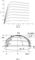
- FIG 8 is a graph showing wheel force maps for different slip angles.
- Each solid curve 710 represents the range of forces available due to changes in braking torque for a given slip angle, with terminal value corresponding to a locked wheel. For instance, the curve 710 starts at A where almost no torque is applied. Higher and higher braking torque is then applied until a point B where maximum longitudinal force is being generated. After this point non-linear behavior causes the longitudinal force to decrease if even more braking torque is applied.
- the graph also shown curves corresponding to Hamiltonian values.
- the dynamic configuration of slip limits can be implemented advantageously using a modified Hamiltonian (MHA) framework.
- MHA modified Hamiltonian
- Figure 9 shows an example system diagram of how MHA may in determining slip limits.
- the states and co-states can be solved numerically off-line, which is often referred to as a two-point boundary value problem.
- the co-state ⁇ is associated with the yaw moment M z , to be specific ⁇ is updated continuously to track a desired yaw moment M z,d to ensure the stability of the vehicle.
- the formulation of M z,d can vary somewhat depending on different stability requirements etc. It is often related to yaw rate error from the reference yaw rate and sideslip angle at the center of gravity location.
- ⁇ represents the yaw angle of the vehicle
- R ( ⁇ ) is a rotational matrix for rotation by ⁇ . Note that both F x g F y g and F x v F y v are exerted on the center of gravity location.
- Figure 8 shows a practical example of how the Hamiltonian function H i is minimized over iterations in time.
- the series of tyre curves represent the range of tyre forces available due to changes in braking torque for a range of tyre sideslip angles.
- the local co-states p ⁇ x , t t p ⁇ y , t t are estimated according to the formula, which determines the slop of the Hamiltonian function, represented by the series of straight lines 720.
- the H i steepest descent direction is perpendicular to the constant H i lines.
- the minimum H i is reached at the circle marker, which corresponds to a braking force around -1250 N and the longitudinal slip ratio (determined by the aforementioned tyre model).
- a range of slip ratios [-0.2:0.001:0] is swept through as the optimal control variable to the combined slip tyre model, together with other inputs such as slip angle ⁇ , tyre normal load F z (both can be estimated on fly), to calculate the constant H i .
- To find the minimum H i a linear one dimensional search is performed. This process is repeated each iteration, typically around 10ms, for each of the wheels on the vehicle 100.
- the optimal longitudinal slips determined in this manner provides the dynamic slip limits which constitute the output of the control allocator 450.
- FIG 10 is a flow chart illustrating methods which summarize at least some of the discussions above.
- a computer-implemented method performed in a vehicle control unit 130, 140 for controlling motion of a heavy-duty vehicle 100.
- the method comprises obtaining S1 a vehicle motion request, wherein the vehicle motion request is indicative of a target curvature c req and a target acceleration a req , c req .
- This motion request may, e.g., be obtained S11 from a driver input and/or from an autonomous or semi-autonomous TSM function 270, as discussed above in connection to Figures 2 , 4 , and 5 .
- the method also comprises determining S2 an MSD control allocation T i / ⁇ i / ⁇ i / ⁇ i / ⁇ i based on the vehicle motion request.
- This MSD control allocation is determined as a force allocation which generates a vehicle motion in accordance with the motion request.
- the method comprises determining S21 the MSD control allocation T i / ⁇ i / ⁇ i / ⁇ i / ⁇ i based on a B-matrix control allocation method based on an optimization evolving the vehicle motion request and a motion model of the vehicle.
- B-matrix control allocation methods are generally known and will therefore not be discussed in more detail herein.
- the MSD control may at least partly be determined S22 as a target wheel torque T i .
- MSDs such as friction brakes and various propulsion devices may be controlled based on a target torque.
- This target torque is submitted to the respective MSD controller as a torque request, whereupon the MSD controller controls the MSAD to generate an actual torque corresponding to the torque request.
- the method comprises determining S23 the MSD control allocation at least partly as a target wheel slip ⁇ i or wheel speed relative to ground ⁇ i .
- This type of control is associated with some advantages. For instance, a controlled vehicle start may be achieved in an efficient manner, since control is based directly on wheel slip, or wheel speed difference with respect to the velocity of the vehicle, as opposed to more traditional forms of torque-based control.
- the MSD control allocation may also comprise determining S24 the MSD control allocation at least partly as a target steering angle ⁇ i .
- This target steering angle will generate lateral force in accordance with the obtained vehicle motion request. It is noted that the target steering angle may be advantageously controlled in dependence of the predicted sideslip. Sideslip can in some cases have a profound effect on the possibility of generating wheel force, as was discussed above in connection to Figure 6 and Figure 8 . In some scenarios, it may be beneficial to reduce the steering angle and instead steer by braking, i.e., apply a different torque on the two sides of a vehicle unit in order to generate a yaw moment.
- the method also comprises determining S3 a dynamic longitudinal wheel slip limit ⁇ lim / ⁇ lim based on the vehicle motion request and separately from the MSD control allocation, where the dynamic longitudinal wheel slip limit increases with a decreasing target curvature.
- This part of the method is key to obtaining the main advantages discussed above.
- By configuring the slip limits dynamically smaller margins can be used as long as no significant lateral forces are required to meet the motion requests from the higher layer control functions.
- the techniques disclosed herein provide examples of methods which are able to determine suitable slip limits that allow generation of the required wheel forces, and which are not unnecessarily limiting the ability to, e.g., generate longitudinal wheel force.
- the methods therefore increase the maneuverability of a heavy-duty vehicle, such as the vehicle 100 discussed above in connection to Figure 1 . Consequently, controlling S4 the motion of the heavy-duty vehicle 100 based on the MSD control allocation constrained by the dynamic longitudinal wheel slip limit implies an improved performance by the vehicle 100.
- the method comprises determining S31 the dynamic longitudinal wheel slip limit ⁇ lim / ⁇ lim based on a current wheel slip angle ⁇ and on a required lateral force, where the dynamic longitudinal wheel slip limit ⁇ lim / ⁇ lim decreases if the current wheel slip angle ⁇ increases.
- the dynamic longitudinal wheel slip limit ⁇ lim / ⁇ lim decreases if the current wheel slip angle ⁇ increases.
- the methods may comprise determining S32 a dynamic steering angle limit ⁇ lim in addition to the dynamic longitudinal wheel slip limit ⁇ lim / ⁇ lim .
- This dynamic steering angle limit effectively limits wheel sideslip, which is an advantage.
- the method comprises determining the dynamic longitudinal wheel slip limit ⁇ lim / ⁇ lim by executing S34 a Hamiltonian algorithm comprising minimizing S35 local Hamiltonian functions at one or more wheels. Each minimization might comprise a linear search of a tyre force curve.
- This approach to determining wheel slip limits was discussed in detail above in connection to Figure 9 .
- the methods may also comprise determining S36 the dynamic longitudinal wheel slip limit ⁇ lim / ⁇ lim based on a stability condition involving a maximum acceptable yaw moment M z of the vehicle 100.
- FIG. 11 schematically illustrates, in terms of a number of functional units, the components of a control unit such as the VCU 130, 140.
- the control unit may implement one or more of the above discussed functions of the TSM 270, VMPM 260 and/or the MSD control function 230, according to embodiments of the discussions herein.
- the control unit is configured to execute at least some of the functions discussed above for control of a heavy-duty vehicle 100.
- Processing circuitry 1110 is provided using any combination of one or more of a suitable central processing unit CPU, multiprocessor, microcontroller, digital signal processor DSP, etc., capable of executing software instructions stored in a computer program product, e.g. in the form of a storage medium 1120.
- the processing circuitry 1110 may further be provided as at least one application specific integrated circuit ASIC, or field programmable gate array FPGA.
- the processing circuitry 1110 is configured to cause the control unit 101 to perform a set of operations, or steps, such as the methods discussed in connection to Figure 10 .
- the storage medium 1120 may store the set of operations
- the processing circuitry 1110 may be configured to retrieve the set of operations from the storage medium 1120 to cause the control unit 130, 140 to perform the set of operations.
- the set of operations may be provided as a set of executable instructions.
- the processing circuitry 1110 is thereby arranged to execute methods as herein disclosed.
- the storage medium 1120 may also comprise persistent storage, which, for example, can be any single one or combination of magnetic memory, optical memory, solid state memory or even remotely mounted memory.
- the control unit 130, 140 may further comprise an interface 1130 for communications with at least one external device.
- the interface 1130 may comprise one or more transmitters and receivers, comprising analogue and digital components and a suitable number of ports for wireline or wireless communication.
- the processing circuitry 1110 controls the general operation of the control unit 130, 140, e.g., by sending data and control signals to the interface 1130 and the storage medium 1120, by receiving data and reports from the interface 1130, and by retrieving data and instructions from the storage medium 1120.
- Other components, as well as the related functionality, of the control node are omitted in order not to obscure the concepts presented herein.
- Figure 12 illustrates a computer readable medium 1210 carrying a computer program comprising program code means 1220 for performing the methods illustrated in Figure 10 , when said program product is run on a computer.
- the computer readable medium and the code means may together form a computer program product 1200.
Landscapes
- Engineering & Computer Science (AREA)
- Transportation (AREA)
- Mechanical Engineering (AREA)
- Automation & Control Theory (AREA)
- Regulating Braking Force (AREA)
Claims (14)
- Procédé mis en œuvre par ordinateur dans une unité de commande de véhicule (130, 140) pour commander le mouvement d'un véhicule lourd (100), le procédé comprenantl'obtention (S1) d'une demande de mouvement de véhicule, dans lequel la demande de mouvement de véhicule indique une courbure cible (creq) et une accélération cible (areq),la détermination (S2) d'une allocation de commande (Ti/λi/ωi/δi) de dispositif d'assistance au mouvement, MSD, sur la base de la demande de mouvement de véhicule, le procédé comprenantla détermination (S3) d'une limite de patinage longitudinal dynamique de roue (λlim/ωlim) sur la base de la demande de mouvement de véhicule et séparément à partir de l'allocation de commande, MSD, où la limite de patinage longitudinal dynamique de roue augmente avec une diminution de courbure cible, et où la limite de patinage longitudinal dynamique de roue (λlim/ωlim) est déterminée en minimisant (S35) des fonctions hamiltoniennes locales au niveau d'une ou plusieurs roues, etla commande (S4) du mouvement du véhicule lourd (100) sur la base de l'allocation de commande MSD contrainte par la limite de patinage longitudinal dynamique de roue.
- Procédé selon la revendication 1, comprenant l'obtention (S11) de la demande de mouvement de véhicule à partir d'une entrée de conducteur et/ou d'une fonction de gestion de situation de trafic, TSM, autonome ou semi-autonome (270).
- Procédé selon la revendication 1 ou 2, comprenant la détermination (S21) de l'allocation de commande MSD (Ti/λi/ωi/δi) sur la base d'un procédé d'allocation de commande de matrice B.
- Procédé selon l'une quelconque des revendications précédentes, comprenant la détermination (S22) de l'allocation de commande MSD au moins en partie comme couple de roue cible (Ti).
- Procédé selon l'une quelconque des revendications précédentes, comprenant la détermination (S23) de l'allocation de commande MSD au moins en partie comme un patinage de roue cible (λi) ou une vitesse de roue par rapport au sol (ωi).
- Procédé selon l'une quelconque des revendications précédentes, comprenant la détermination (S24) de l'allocation de commande MSD au moins en partie comme un angle de braquage cible (δi).
- Procédé selon l'une quelconque des revendications précédentes, comprenant la détermination (S31) de la limite de patinage longitudinal dynamique de roue (λlim/ωlim) sur la base d'un angle de patinage de roue actuel (α) et d'une force latérale requise, où la limite de patinage longitudinal dynamique de roue (λlim/ωlim) diminue si l'angle de patinage de roue actuel (α) augmente.
- Procédé selon l'une quelconque des revendications précédentes, comprenant la détermination (S32) d'une limite d'angle de braquage dynamique (δlim) en plus de la limite de patinage longitudinal dynamique de roue (λlim/ωlim).
- Procédé selon l'une quelconque des revendications précédentes, dans lequel chaque minimisation des fonctions hamiltoniennes locales au niveau d'une ou plusieurs roues comprend une recherche linéaire d'une courbe de force de pneu.
- Procédé selon l'une quelconque des revendications précédentes, comprenant la détermination (S36) de la limite de patinage longitudinal dynamique de roue (λlim/ωlim) sur la base d'une condition de stabilité impliquant un moment de lacet maximal acceptable (Mz) du véhicule (100).
- Programme informatique (1220) comprenant des moyens de code de programme pour exécuter les étapes selon l'une quelconque des revendications 1 à 10, lorsque ledit programme est exécuté sur un ordinateur ou sur un circuit de traitement (1110) d'une unité de commande (130,140).
- Support lisible par ordinateur (1210) portant un programme informatique (1220) comprenant des moyens de code de programme pour exécuter les étapes selon l'une quelconque des revendications 1 à 10 lorsque ledit produit de programme est exécuté sur un ordinateur ou sur un circuit de traitement (1110) d'une unité de commande (130,140).
- Unité de commande (130,140), comprenant :un circuit de traitement (1110) ;une interface (1130) couplée au circuit de traitement (1110) ; etune mémoire (1120) couplée au circuit de traitement (1110), dans laquelle la mémoire comprend des instructions de programme informatique lisibles par machine qui, lorsqu'elles sont exécutées par le circuit de traitement, amènent l'unité de commande à effectuer les opérations consistant à :obtenir (S1) une demande de mouvement de véhicule, dans laquelle la demande de mouvement de véhicule indique une courbure cible (creq) et une accélération cible (areq),déterminer (S2) une allocation de commande (Ti/λi/ωi/δi) de dispositif d'assistance au mouvement, MSD, sur la base de la demande de mouvement de véhicule,déterminer (S3) une limite de patinage longitudinal dynamique de roue (λlim/ωlim) sur la base de la demande de mouvement de véhicule et séparément à partir de l'allocation de commande MSD, où la limite de patinage longitudinal dynamique de roue augmente avec une diminution de courbure cible, et où la limite de patinage longitudinal dynamique de roue (λlim/ωlim) est déterminé en minimisant des fonctions hamiltoniennes locales au niveau d'une ou plusieurs roues, etcommander (S4) le mouvement du véhicule lourd (100) sur la base de l'allocation de commande MSD contrainte par la limite de patinage longitudinal dynamique de roue.
- Véhicule lourd (100) comprenant une unité de commande (130, 140) selon la revendication 13.
Applications Claiming Priority (1)
| Application Number | Priority Date | Filing Date | Title |
|---|---|---|---|
| PCT/EP2021/060858 WO2022228653A1 (fr) | 2021-04-26 | 2021-04-26 | Commande de véhicule basée sur des limites de patinage longitudinal de roue configurées dynamiquement |
Publications (2)
| Publication Number | Publication Date |
|---|---|
| EP4330097A1 EP4330097A1 (fr) | 2024-03-06 |
| EP4330097B1 true EP4330097B1 (fr) | 2025-05-28 |
Family
ID=75746602
Family Applications (1)
| Application Number | Title | Priority Date | Filing Date |
|---|---|---|---|
| EP21722407.0A Active EP4330097B1 (fr) | 2021-04-26 | 2021-04-26 | Commande de véhicule basée sur des limites de patinage longitudinal de roue configurées dynamiquement |
Country Status (3)
| Country | Link |
|---|---|
| US (1) | US12515639B2 (fr) |
| EP (1) | EP4330097B1 (fr) |
| WO (1) | WO2022228653A1 (fr) |
Cited By (1)
| Publication number | Priority date | Publication date | Assignee | Title |
|---|---|---|---|---|
| US20240182019A1 (en) * | 2021-04-26 | 2024-06-06 | Volvo Truck Corporation | Vehicle control based on dynamically configured longitudinal wheel slip limits |
Families Citing this family (6)
| Publication number | Priority date | Publication date | Assignee | Title |
|---|---|---|---|---|
| US12594914B2 (en) * | 2023-08-03 | 2026-04-07 | Steering Solutions Ip Holding Corporation | Brake-to-steer lateral stability management based on stability indicator correlation |
| US12600346B2 (en) | 2023-08-03 | 2026-04-14 | Steering Solutions Ip Holding Corporation | Brake-to-steer lateral stability management based on stability indicator correlation |
| US12539841B2 (en) | 2023-08-03 | 2026-02-03 | Steering Solutions IP Holding Corporation Continental Automotive Systems Inc | Brake-to-Steer lateral stability management based on stability indicator correlation |
| WO2025061281A1 (fr) * | 2023-09-20 | 2025-03-27 | Volvo Truck Corporation | Limitation de glissement d'un véhicule |
| EP4696574A1 (fr) * | 2024-08-15 | 2026-02-18 | Volvo Truck Corporation | Commande de vitesse de rotation pour essieux directeurs de véhicule |
| CN119459660B (zh) * | 2024-11-08 | 2025-11-07 | 南京汽车集团有限公司 | 一种带有延迟补偿和打滑抑制的重型商用车辆横摆控制系统及方法 |
Family Cites Families (20)
| Publication number | Priority date | Publication date | Assignee | Title |
|---|---|---|---|---|
| JP3601487B2 (ja) * | 2000-11-20 | 2004-12-15 | トヨタ自動車株式会社 | 車輌の制駆動力制御装置 |
| JP2008247067A (ja) * | 2007-03-29 | 2008-10-16 | Mazda Motor Corp | 車両の運動制御装置 |
| CN103879401A (zh) | 2012-12-24 | 2014-06-25 | 李果 | 有力控制的汽车转向和制动系统的一致协同控制技术 |
| DE102013016434A1 (de) * | 2013-10-02 | 2015-04-02 | Audi Ag | Kraftfahrzeug und Verfahren zur Steuerung eines Kraftfahrzeugs |
| WO2017076436A1 (fr) * | 2015-11-03 | 2017-05-11 | Volvo Truck Corporation | Système et procédé de commande d'un véhicule comprenant un système de freinage d'urgence autonome |
| GB201707973D0 (en) | 2017-05-18 | 2017-07-05 | Jaguar Land Rover Ltd | A vehicle control system, method and computer program for a vehicle control multilayer architecture |
| WO2019072379A1 (fr) | 2017-10-10 | 2019-04-18 | Volvo Truck Corporation | Procédé de commande du système de direction d'un véhicule |
| CN109017759B (zh) * | 2018-07-31 | 2022-04-08 | 大连民族大学 | 期望路径车辆横摆控制方法 |
| CN109017804B (zh) * | 2018-07-31 | 2022-01-18 | 大连民族大学 | 力矩分配控制器为车辆各轮毂电机分配驱动力矩的方法 |
| CN109017446B (zh) * | 2018-07-31 | 2020-10-23 | 大连民族大学 | 期待路径车辆纵向速度追踪控制方法及装置 |
| CN109017447B (zh) * | 2018-07-31 | 2021-08-10 | 大连民族大学 | 无人驾驶车辆总的驱动力矩输出方法 |
| CN109017760B (zh) * | 2018-07-31 | 2022-04-12 | 大连民族大学 | 车辆期望轨迹跟踪方法、装置及滚动时域优化算法 |
| CN109017778B (zh) * | 2018-07-31 | 2022-04-15 | 大连民族大学 | 四轮独立驱动车辆的期望路径主动转向控制方法 |
| US12330653B2 (en) * | 2019-06-14 | 2025-06-17 | Volvo Truck Corporation | Method for validating a model associated with vehicle dynamics |
| EP4330097B1 (fr) * | 2021-04-26 | 2025-05-28 | Volvo Truck Corporation | Commande de véhicule basée sur des limites de patinage longitudinal de roue configurées dynamiquement |
| EP4140839B1 (fr) * | 2021-08-31 | 2024-10-30 | Volvo Truck Corporation | Commande de véhicule basé sur une limite de dérapage configurée de manière dynamique |
| CN114312750B (zh) * | 2022-01-18 | 2022-08-09 | 郑州轻工业大学 | 一种主动转向和横摆力矩自学习协同控制方法 |
| FR3142423B1 (fr) * | 2022-11-25 | 2024-10-11 | Vitesco Technologies | Procede d’optimisation de la consommation en energie d’un vehicule automobile |
| CN116279409B (zh) * | 2023-02-03 | 2025-12-19 | 同济大学 | 一种四轮独立驱动与转向电动汽车的协同控制方法 |
| CN116279408B (zh) * | 2023-02-03 | 2025-12-12 | 同济大学 | 一种基于快速求解算法的车辆纵侧向运动协同控制方法 |
-
2021
- 2021-04-26 EP EP21722407.0A patent/EP4330097B1/fr active Active
- 2021-04-26 WO PCT/EP2021/060858 patent/WO2022228653A1/fr not_active Ceased
- 2021-04-26 US US18/287,496 patent/US12515639B2/en active Active
Cited By (2)
| Publication number | Priority date | Publication date | Assignee | Title |
|---|---|---|---|---|
| US20240182019A1 (en) * | 2021-04-26 | 2024-06-06 | Volvo Truck Corporation | Vehicle control based on dynamically configured longitudinal wheel slip limits |
| US12515639B2 (en) * | 2021-04-26 | 2026-01-06 | Volvo Truck Corporation | Vehicle control based on dynamically configured longitudinal wheel slip limits |
Also Published As
| Publication number | Publication date |
|---|---|
| WO2022228653A1 (fr) | 2022-11-03 |
| US20240182019A1 (en) | 2024-06-06 |
| EP4330097A1 (fr) | 2024-03-06 |
| US12515639B2 (en) | 2026-01-06 |
Similar Documents
| Publication | Publication Date | Title |
|---|---|---|
| US12358509B2 (en) | Vehicle control based on a dynamically configured sideslip limit | |
| EP4330097B1 (fr) | Commande de véhicule basée sur des limites de patinage longitudinal de roue configurées dynamiquement | |
| EP3851346B1 (fr) | Modèle de pneu inverse pour la gestion avancée de mouvement de véhicule | |
| EP4247695B1 (fr) | Gestion prédictive d'énergie et de mouvement pour véhicules utilitaires lourds à plusieurs remorques | |
| EP4247686B1 (fr) | Procédé de réduction de dérive à haute vitesse dans des véhicules utilitaires lourds à plusieurs remorques | |
| EP4108529B1 (fr) | Procédé permettant de commander la propulsion d'un véhicule utilitaire lourd | |
| EP4396063B1 (fr) | Commande de véhicule pour conduite autonome simplifiée | |
| EP4490002B1 (fr) | Systeme de capteur pour determiner la vitesse du vehicule sur le sol | |
| EP4490004B1 (fr) | Systeme de capteur pour determiner la vitesse du vehicule sur le sol | |
| US12570295B2 (en) | Fast free-rolling of wheels for robust vehicle speed over ground determination | |
| WO2023169700A1 (fr) | Roulement libre sélectif de roues pour détermination de vitesse au sol de véhicule robuste | |
| EP4355602B1 (fr) | Procédé pour commander la propulsion d'un véhicule utilitaire lourd |
Legal Events
| Date | Code | Title | Description |
|---|---|---|---|
| STAA | Information on the status of an ep patent application or granted ep patent |
Free format text: STATUS: UNKNOWN |
|
| STAA | Information on the status of an ep patent application or granted ep patent |
Free format text: STATUS: THE INTERNATIONAL PUBLICATION HAS BEEN MADE |
|
| PUAI | Public reference made under article 153(3) epc to a published international application that has entered the european phase |
Free format text: ORIGINAL CODE: 0009012 |
|
| STAA | Information on the status of an ep patent application or granted ep patent |
Free format text: STATUS: REQUEST FOR EXAMINATION WAS MADE |
|
| 17P | Request for examination filed |
Effective date: 20231011 |
|
| AK | Designated contracting states |
Kind code of ref document: A1 Designated state(s): AL AT BE BG CH CY CZ DE DK EE ES FI FR GB GR HR HU IE IS IT LI LT LU LV MC MK MT NL NO PL PT RO RS SE SI SK SM TR |
|
| DAV | Request for validation of the european patent (deleted) | ||
| DAX | Request for extension of the european patent (deleted) | ||
| GRAP | Despatch of communication of intention to grant a patent |
Free format text: ORIGINAL CODE: EPIDOSNIGR1 |
|
| STAA | Information on the status of an ep patent application or granted ep patent |
Free format text: STATUS: GRANT OF PATENT IS INTENDED |
|
| INTG | Intention to grant announced |
Effective date: 20241204 |
|
| GRAS | Grant fee paid |
Free format text: ORIGINAL CODE: EPIDOSNIGR3 |
|
| RIN1 | Information on inventor provided before grant (corrected) |
Inventor name: PROKES, JAKUB Inventor name: HENDERSON, LEON Inventor name: GAO, YANGYAN |
|
| GRAA | (expected) grant |
Free format text: ORIGINAL CODE: 0009210 |
|
| STAA | Information on the status of an ep patent application or granted ep patent |
Free format text: STATUS: THE PATENT HAS BEEN GRANTED |
|
| AK | Designated contracting states |
Kind code of ref document: B1 Designated state(s): AL AT BE BG CH CY CZ DE DK EE ES FI FR GB GR HR HU IE IS IT LI LT LU LV MC MK MT NL NO PL PT RO RS SE SI SK SM TR |
|
| REG | Reference to a national code |
Ref country code: GB Ref legal event code: FG4D |
|
| REG | Reference to a national code |
Ref country code: CH Ref legal event code: EP |
|
| REG | Reference to a national code |
Ref country code: IE Ref legal event code: FG4D Ref country code: DE Ref legal event code: R096 Ref document number: 602021031428 Country of ref document: DE |
|
| REG | Reference to a national code |
Ref country code: NL Ref legal event code: MP Effective date: 20250528 |
|
| PG25 | Lapsed in a contracting state [announced via postgrant information from national office to epo] |
Ref country code: ES Free format text: LAPSE BECAUSE OF FAILURE TO SUBMIT A TRANSLATION OF THE DESCRIPTION OR TO PAY THE FEE WITHIN THE PRESCRIBED TIME-LIMIT Effective date: 20250528 Ref country code: FI Free format text: LAPSE BECAUSE OF FAILURE TO SUBMIT A TRANSLATION OF THE DESCRIPTION OR TO PAY THE FEE WITHIN THE PRESCRIBED TIME-LIMIT Effective date: 20250528 |
|
| REG | Reference to a national code |
Ref country code: LT Ref legal event code: MG9D |
|
| PG25 | Lapsed in a contracting state [announced via postgrant information from national office to epo] |
Ref country code: GR Free format text: LAPSE BECAUSE OF FAILURE TO SUBMIT A TRANSLATION OF THE DESCRIPTION OR TO PAY THE FEE WITHIN THE PRESCRIBED TIME-LIMIT Effective date: 20250829 Ref country code: NO Free format text: LAPSE BECAUSE OF FAILURE TO SUBMIT A TRANSLATION OF THE DESCRIPTION OR TO PAY THE FEE WITHIN THE PRESCRIBED TIME-LIMIT Effective date: 20250828 |
|
| PG25 | Lapsed in a contracting state [announced via postgrant information from national office to epo] |
Ref country code: PL Free format text: LAPSE BECAUSE OF FAILURE TO SUBMIT A TRANSLATION OF THE DESCRIPTION OR TO PAY THE FEE WITHIN THE PRESCRIBED TIME-LIMIT Effective date: 20250528 Ref country code: NL Free format text: LAPSE BECAUSE OF FAILURE TO SUBMIT A TRANSLATION OF THE DESCRIPTION OR TO PAY THE FEE WITHIN THE PRESCRIBED TIME-LIMIT Effective date: 20250528 |
|
| PG25 | Lapsed in a contracting state [announced via postgrant information from national office to epo] |
Ref country code: BG Free format text: LAPSE BECAUSE OF FAILURE TO SUBMIT A TRANSLATION OF THE DESCRIPTION OR TO PAY THE FEE WITHIN THE PRESCRIBED TIME-LIMIT Effective date: 20250528 |
|
| PG25 | Lapsed in a contracting state [announced via postgrant information from national office to epo] |
Ref country code: HR Free format text: LAPSE BECAUSE OF FAILURE TO SUBMIT A TRANSLATION OF THE DESCRIPTION OR TO PAY THE FEE WITHIN THE PRESCRIBED TIME-LIMIT Effective date: 20250528 |
|
| PG25 | Lapsed in a contracting state [announced via postgrant information from national office to epo] |
Ref country code: RS Free format text: LAPSE BECAUSE OF FAILURE TO SUBMIT A TRANSLATION OF THE DESCRIPTION OR TO PAY THE FEE WITHIN THE PRESCRIBED TIME-LIMIT Effective date: 20250828 |
|
| PG25 | Lapsed in a contracting state [announced via postgrant information from national office to epo] |
Ref country code: IS Free format text: LAPSE BECAUSE OF FAILURE TO SUBMIT A TRANSLATION OF THE DESCRIPTION OR TO PAY THE FEE WITHIN THE PRESCRIBED TIME-LIMIT Effective date: 20250928 |
|
| PG25 | Lapsed in a contracting state [announced via postgrant information from national office to epo] |
Ref country code: LV Free format text: LAPSE BECAUSE OF FAILURE TO SUBMIT A TRANSLATION OF THE DESCRIPTION OR TO PAY THE FEE WITHIN THE PRESCRIBED TIME-LIMIT Effective date: 20250528 |
|
| REG | Reference to a national code |
Ref country code: AT Ref legal event code: MK05 Ref document number: 1798483 Country of ref document: AT Kind code of ref document: T Effective date: 20250528 |
|
| PG25 | Lapsed in a contracting state [announced via postgrant information from national office to epo] |
Ref country code: AT Free format text: LAPSE BECAUSE OF FAILURE TO SUBMIT A TRANSLATION OF THE DESCRIPTION OR TO PAY THE FEE WITHIN THE PRESCRIBED TIME-LIMIT Effective date: 20250528 Ref country code: DK Free format text: LAPSE BECAUSE OF FAILURE TO SUBMIT A TRANSLATION OF THE DESCRIPTION OR TO PAY THE FEE WITHIN THE PRESCRIBED TIME-LIMIT Effective date: 20250528 Ref country code: SM Free format text: LAPSE BECAUSE OF FAILURE TO SUBMIT A TRANSLATION OF THE DESCRIPTION OR TO PAY THE FEE WITHIN THE PRESCRIBED TIME-LIMIT Effective date: 20250528 |
|
| PG25 | Lapsed in a contracting state [announced via postgrant information from national office to epo] |
Ref country code: CZ Free format text: LAPSE BECAUSE OF FAILURE TO SUBMIT A TRANSLATION OF THE DESCRIPTION OR TO PAY THE FEE WITHIN THE PRESCRIBED TIME-LIMIT Effective date: 20250528 |
|
| PG25 | Lapsed in a contracting state [announced via postgrant information from national office to epo] |
Ref country code: EE Free format text: LAPSE BECAUSE OF FAILURE TO SUBMIT A TRANSLATION OF THE DESCRIPTION OR TO PAY THE FEE WITHIN THE PRESCRIBED TIME-LIMIT Effective date: 20250528 |
|
| PG25 | Lapsed in a contracting state [announced via postgrant information from national office to epo] |
Ref country code: SK Free format text: LAPSE BECAUSE OF FAILURE TO SUBMIT A TRANSLATION OF THE DESCRIPTION OR TO PAY THE FEE WITHIN THE PRESCRIBED TIME-LIMIT Effective date: 20250528 |
|
| PG25 | Lapsed in a contracting state [announced via postgrant information from national office to epo] |
Ref country code: IT Free format text: LAPSE BECAUSE OF FAILURE TO SUBMIT A TRANSLATION OF THE DESCRIPTION OR TO PAY THE FEE WITHIN THE PRESCRIBED TIME-LIMIT Effective date: 20250528 |
|
| REG | Reference to a national code |
Ref country code: DE Ref legal event code: R097 Ref document number: 602021031428 Country of ref document: DE |
|
| PLBE | No opposition filed within time limit |
Free format text: ORIGINAL CODE: 0009261 |
|
| STAA | Information on the status of an ep patent application or granted ep patent |
Free format text: STATUS: NO OPPOSITION FILED WITHIN TIME LIMIT |
|
| REG | Reference to a national code |
Ref country code: CH Ref legal event code: L10 Free format text: ST27 STATUS EVENT CODE: U-0-0-L10-L00 (AS PROVIDED BY THE NATIONAL OFFICE) Effective date: 20260409 |