EP4330162B1 - Entrepôt de marchandises avec allées carrossables - Google Patents
Entrepôt de marchandises avec allées carrossables Download PDFInfo
- Publication number
- EP4330162B1 EP4330162B1 EP22722711.3A EP22722711A EP4330162B1 EP 4330162 B1 EP4330162 B1 EP 4330162B1 EP 22722711 A EP22722711 A EP 22722711A EP 4330162 B1 EP4330162 B1 EP 4330162B1
- Authority
- EP
- European Patent Office
- Prior art keywords
- rail
- limb
- vertical
- storage facility
- facility according
- Prior art date
- Legal status (The legal status is an assumption and is not a legal conclusion. Google has not performed a legal analysis and makes no representation as to the accuracy of the status listed.)
- Active
Links
Images

Classifications
-
- B—PERFORMING OPERATIONS; TRANSPORTING
- B65—CONVEYING; PACKING; STORING; HANDLING THIN OR FILAMENTARY MATERIAL
- B65G—TRANSPORT OR STORAGE DEVICES, e.g. CONVEYORS FOR LOADING OR TIPPING, SHOP CONVEYOR SYSTEMS OR PNEUMATIC TUBE CONVEYORS
- B65G1/00—Storing articles, individually or in orderly arrangement, in warehouses or magazines
- B65G1/02—Storage devices
-
- B—PERFORMING OPERATIONS; TRANSPORTING
- B65—CONVEYING; PACKING; STORING; HANDLING THIN OR FILAMENTARY MATERIAL
- B65G—TRANSPORT OR STORAGE DEVICES, e.g. CONVEYORS FOR LOADING OR TIPPING, SHOP CONVEYOR SYSTEMS OR PNEUMATIC TUBE CONVEYORS
- B65G41/00—Supporting frames or bases for conveyors as a whole, e.g. transportable conveyor frames
- B65G41/006—Supporting frames or bases for conveyors as a whole, e.g. transportable conveyor frames with the conveyor not adjustably mounted on the supporting frame or base
-
- F—MECHANICAL ENGINEERING; LIGHTING; HEATING; WEAPONS; BLASTING
- F16—ENGINEERING ELEMENTS AND UNITS; GENERAL MEASURES FOR PRODUCING AND MAINTAINING EFFECTIVE FUNCTIONING OF MACHINES OR INSTALLATIONS; THERMAL INSULATION IN GENERAL
- F16M—FRAMES, CASINGS OR BEDS OF ENGINES, MACHINES OR APPARATUS, NOT SPECIFIC TO ENGINES, MACHINES OR APPARATUS PROVIDED FOR ELSEWHERE; STANDS; SUPPORTS
- F16M11/00—Stands or trestles as supports for apparatus or articles placed thereon ; Stands for scientific apparatus such as gravitational force meters
- F16M11/42—Stands or trestles as supports for apparatus or articles placed thereon ; Stands for scientific apparatus such as gravitational force meters with arrangement for propelling the support stands on wheels
- F16M11/425—Stands or trestles as supports for apparatus or articles placed thereon ; Stands for scientific apparatus such as gravitational force meters with arrangement for propelling the support stands on wheels along guiding means
-
- B—PERFORMING OPERATIONS; TRANSPORTING
- B65—CONVEYING; PACKING; STORING; HANDLING THIN OR FILAMENTARY MATERIAL
- B65G—TRANSPORT OR STORAGE DEVICES, e.g. CONVEYORS FOR LOADING OR TIPPING, SHOP CONVEYOR SYSTEMS OR PNEUMATIC TUBE CONVEYORS
- B65G1/00—Storing articles, individually or in orderly arrangement, in warehouses or magazines
- B65G1/02—Storage devices
- B65G1/04—Storage devices mechanical
- B65G1/0492—Storage devices mechanical with cars adapted to travel in storage aisles
-
- B—PERFORMING OPERATIONS; TRANSPORTING
- B65—CONVEYING; PACKING; STORING; HANDLING THIN OR FILAMENTARY MATERIAL
- B65G—TRANSPORT OR STORAGE DEVICES, e.g. CONVEYORS FOR LOADING OR TIPPING, SHOP CONVEYOR SYSTEMS OR PNEUMATIC TUBE CONVEYORS
- B65G1/00—Storing articles, individually or in orderly arrangement, in warehouses or magazines
- B65G1/02—Storage devices
- B65G1/04—Storage devices mechanical
- B65G1/06—Storage devices mechanical with means for presenting articles for removal at predetermined position or level
- B65G1/065—Storage devices mechanical with means for presenting articles for removal at predetermined position or level with self propelled cars
Definitions
- the invention relates to a warehouse with a base frame made of vertical supports and horizontal cross members and at least one aisle leading through the base frame for the storage and retrieval of goods by means of a carrier which can be moved on two rails in the aisle, wherein the respective rail consists of a horizontal leg which forms a running surface for the carrier, and at least one vertical leg, wherein the rail is fastened at least indirectly to one of the supports and/or cross members by means of fastening elements, preferably screw connections, in a fastening area which extends only over a partial length of the rail, and wherein the vertical leg is provided in the fastening area with holes through which the fastening elements lead.
- fastening elements preferably screw connections
- warehouses such as those from the DE 10 2019 104 372 A1 are known as general cargo warehouses in which the loading units, e.g., goods or pallets loaded with goods, are arranged one behind the other in individual channels or are stored on either side of an aisle.
- a self-propelled distribution vehicle often referred to as a “shuttle” or “carrier,” is used for storing, retrieving, or relocating the goods. This vehicle is designed to drive underneath the goods or load carrier, then lift them, and transport them in this raised state to another location in the warehouse.
- Such distribution vehicles are equipped, in particular, with means for fully automatically lifting the goods or the load carriers supporting the goods, pulling them from the laterally arranged storage positions into the aisle, and then moving them within and along the aisle.
- the rails on which the rollers of the distribution vehicle run are often segmented, i.e., composed of successive rail segments in the shape of profiles.
- the profiles are screwed to the base frame of the warehouse, which primarily consists of vertical supports and horizontal cross beams.
- Critical impulse loads arise particularly where the carrier transfers from a transport device, such as an elevator, to the rail. Often, the running surfaces of the rails and the rails on the elevator are not aligned, but rather have a height difference. When the carrier moves, it may be necessary for its rollers to overcome the height difference. Because the carriers move quickly and are usually heavily loaded, even small height differences trigger impulse loads on the nearest rail attachment area during the carrier transfer.
- the object of the invention is to further develop the known warehouse in such a way that even during prolonged operation, no cracks occur on the rail in the connection area between the rails and the supports or crossbeams.
- the vertical leg of the rail is provided in the fastening region but outside the holes with at least one structural weakening in the form of an opening which extends in a slot-like manner essentially in the longitudinal direction of the rail and is arranged at a height closer to the horizontal leg than to the upper edge of the vertical leg.
- the holes used for fastening purposes are arranged at partly different heights, wherein the structural weakening is arranged below the lowest hole through which one of the fastening elements passes.
- the structural weakening through which no fastening element passes is arranged between the holes through which fastening elements pass and which are closest to the ends of the fastening area in the longitudinal direction of the rail.
- the structural weakening according to the invention even below the lowest holes used to connect the rail to the base frame, results in increased flexibility of the rail in the connection area. Particularly in the case of impulsive loads on the rail, for example, when the carrier is placed on the rail, this increased flexibility in the connection area prevents crack formation originating from the holes in the rail used for fastening purposes. the impulsive load is absorbed in a non-critical deformation of the area around the structural weakening, whereby the energy stored in the elastic deformation is subsequently released again in a complete recovery.
- the structural weakening preferably has a largely rounded contour.
- the rounded or rounded design of the structural weakening ensures favorable force flow and eliminates shape-related notch effects. It is conceivable to produce the opening using a stamping process, with a slight protrusion forming on the side of the rail facing in the stamping direction, which further improves the structural integrity of the opening against cracking.
- the structural weakening consists of two spaced-apart, circular recesses, wherein the recesses are connected by an arcuate slot.
- the structural weakening in the form of an opening is a curved horizontal slot, each with flared ends, located below the lowest hole in the rail.
- the rail is preferably arranged with its fastening area on a bracket via the fastening elements, whereby the bracket is in turn fastened to one of the supports and/or crossbeams.
- the bracket rests at least on the vertical fastening area of the rail and is connected to the rail via screw connections.
- the bracket is fastened to a support or crossbeam, whereby a screw or welded connection is also conceivable.
- other types of connection such as rivets, are generally also possible.
- the warehouse preferably has a support bracket consisting of a vertical and a horizontal leg, wherein the legs extend parallel to the legs of the rail only over a partial length of the rail, wherein the vertical leg of the support bracket is attached to the vertical Leg of the rail is attached via additional fastening elements, and the horizontal leg of the support bracket engages under the horizontal leg of the rail.
- the support bracket is designed to support the rail in the connection area to the support and/or the crossbeam.
- the horizontal leg of the rail preferably rests on the horizontal leg of the support bracket. This means that loads acting on the running surface of the rail are additionally absorbed by the horizontal leg of the rail.
- the horizontal sections of the support bracket and the rail to be designed without direct contact with one another, but for the running surface to sink when a carrier travels over it and come into contact with the horizontal section of the support bracket before any plastic deformation of the running surface relative to the vertical leg of the rail occurs.
- the support angles are in contact with the consoles due to their shape, or that they are connected to the consoles in a form-fitting or material-fitting manner.
- the support brackets are designed to be arranged at the fastening areas of the rails, with several of the fastening areas preferably being arranged at a distance of 1 m to 1.5 m from each other along the rail.
- the fastening areas in the loading and unloading area of a rail are subject to the greatest load, it is also conceivable to arrange the support brackets only in this area.
- the rail preferably has an additional horizontal leg that adjoins the upper edge of the vertical leg and is configured to point away from or toward the aisle. Furthermore, the rail preferably has an additional vertical leg that adjoins the end of the horizontal leg facing the aisle, either downwardly or upwardly.
- the additional legs of the rail provide greater stiffening and a concomitant increase in load-bearing capacity.
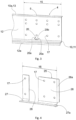
- the Figure 1 shows parts of a base frame as components of a warehouse, namely a vertical support 1 and a horizontal cross member 2 attached to it.
- a rail 4 is attached to the top of the cross member 2, transverse to the cross member 2, which rail 4 is connected between itself and a parallel, a second rail (not shown) forms an aisle 3.
- the aisle 3 is designed for the storage and retrieval of goods by means of a carrier that can be moved along the aisle 3 on the two rails 4.
- the carrier is a motor-driven transport vehicle that can be moved on at least four rollers and under its own power within the warehouse on the rails 4.
- the carrier consists, for example, of a base body that serves both as a support for the goods to be transported and as a storage area for the rollers.
- Each rail 4 consists of a single piece, consisting of a horizontal leg 10, the upper side of which forms the running surface 11 for the carrier, and a vertical leg 12, which represents the lateral running surface limit for the carrier.
- the rail 4 consists of a rectangular, cold-formed steel sheet with a material thickness of 2 mm to 4 mm.
- the rail 4 has a fastening area 15 on its vertical leg 12, which extends only over a partial length of the rail 4.
- the rail 4 is arranged on a bracket 40 only with the fastening area 15.
- several of the fastening areas 15 are arranged distributed over the rail 4.
- the vertical leg 12 of the rail 4 and the bracket 20 are provided with aligned holes 17 in the fastening area 15, through which the rail 4 is fastened to the bracket 40 by means of fastening elements 16 in the form of screw connections.
- the underside of the bracket 40 is fastened, for example, to the cross member 2.
- a support bracket 25 is attached to the back of the rail 4, consisting of a vertical and a horizontal leg 26, 27.
- the legs 26, 27 extend only over a partial length of the rail 4 and are formed parallel to the legs 10, 12 of the rail 4.
- the vertical leg 26 of the support bracket 25 is attached to the vertical leg 12 of the rail 4, with the horizontal leg 27 of the support bracket 25 engaging below the horizontal leg 10 of the rail 4.
- the rail 4 is formed with further holes 17, which are aligned with holes 17 in the support bracket 25.
- further fastening elements 30 in the form of screws or rivets are arranged in the holes 17 of the rail 4 and the support bracket 25.
- the vertical and horizontal legs 26, 27 of the support angle 25 an obliquely widening region 26a, 27a.
- the widened region is formed by the fact that the vertical leg 26, which otherwise runs parallel to the vertical leg 12 of the rail 4, widens in a partial area pointing away from the aisle 3.
- the widened area 26a, 27a of the support bracket 25 is designed such that it extends beyond the end of the rail 4 and thus serves as an insertion aid when the carrier is first driven onto the rail 4.
- the support angle 25 is, according to the Figures 2 and 4 , provided with a recess 28 that allows direct attachment of the bracket 40 to the attachment area 15 of the rail 4. Consequently, the support bracket 25 is designed such that it frames the bracket 40 on at least three sides. Thus, the support bracket 25 is not directly connected to the bracket 40.
- Figure 3 shows a perspective view of the rail 4 with a structural weakening 20 in the vertical leg 12 of the rail.
- the structural weakening 20, through which no fastening element passes and which is therefore open, is located at a height closer to the horizontal leg 10 than to the upper edge 13 of the vertical leg 12 and is preferably located below the lowest hole 17 in the fastening area 15.
- the structural weakening 20 is arranged between the holes 17 that are closest to the ends of the fastening area 15 in the longitudinal direction of the rail 4.
- This arrangement of the structural weakening 20 is intended to ensure that the holes 17 closest to the ends of the fastening area 15 are exclusively designed to be connected to the support bracket 25, so that the support bracket 25 particularly stiffens the sections of the fastening area 15 that surround the structural weakening 20.
- the recesses 20a have a larger diameter than the cross-section of the connecting slot 20b.
- the enlargement of the recesses 20a ensures that the notch effect is further reduced.
Landscapes
- Engineering & Computer Science (AREA)
- Mechanical Engineering (AREA)
- General Engineering & Computer Science (AREA)
- Warehouses Or Storage Devices (AREA)
Claims (11)
- Entrepôt de marchandises avec un châssis de base composé de montants verticaux (1) et de traverses horizontales (2) et avec au moins une allée (3) traversant le châssis de base pour le stockage et le déstockage de marchandises au moyen d'un chariot pouvant se déplacer sur deux rails (4) dans l'allée (3), le rail respectif (4) étant constitué d'une branche horizontale (10), qui forme une surface de roulement (11) pour le chariot, et d'au moins une branche verticale (12), le rail (4) étant fixé dans une zone de fixation (15) qui ne s'étend que sur une longueur partielle du rail (4) au moyen d'éléments de fixation (16), de préférence de liaisons par vis, au moins indirectement à l'un des montants (1) et/ou des traverses (2), et la branche verticale (12) étant pourvue, dans la zone de fixation (15), de trous (17) à travers lesquels passent les éléments de fixation (16), caractérisé en ce que la branche verticale (12) est pourvue, dans la zone de fixation (15) mais à l'extérieur des trous (17), d'au moins un affaiblissement structurel (20) sous la forme d'une ouverture qui s'étend à la manière d'une fente essentiellement dans la direction longitudinale du rail (4) et qui est agencé à une hauteur plus proche de la branche horizontale (10) que du bord supérieur (13) de la branche verticale (12).
- Entrepôt de marchandises selon la revendication 1, caractérisé en ce que les trous (17) sont agencés à des hauteurs partiellement différentes, et en ce que l'affaiblissement structurel (20) est agencé au-dessous du trou (17) agencé le plus bas, à travers lequel passe l'un des éléments de fixation (16).
- Entrepôt de marchandises selon la revendication 1 ou 2, caractérisé en ce que l'affaiblissement structurel (20) est agencé entre les trous (17) qui sont les plus proches des extrémités de la zone de fixation (15) dans la direction longitudinale du rail (4).
- Entrepôt de marchandises selon l'une quelconque des revendications précédentes, caractérisé par une équerre de support (25) composée d'une branche verticale et d'une branche horizontale (26, 27), les branches (26, 27) s'étendant parallèlement aux branches (10, 12) du rail (4) uniquement sur une longueur partielle du rail (4), la branche verticale (26) de l'équerre de support (25) étant fixée à la branche verticale (12) du rail (4) par d'autres éléments de fixation (30), et la branche horizontale (27) de l'équerre de support (25) s'engageant sous la branche horizontale (10) du rail (4).
- Entrepôt de marchandises selon la revendication 4, caractérisé en ce que l'équerre de support (25) présente dans sa branche verticale (26) un évidement (28) qui permet une fixation au moins indirecte de la zone de fixation (15) du rail (4) sur un montant (1) ou/et une traverse (2).
- Entrepôt de marchandises selon l'une quelconque des revendications 4 ou 5, caractérisé en ce qu'une zone (26a, 27a) s'élargissant par rapport à l'allée (3) se trouve sur la branche verticale et la branche horizontale (26, 27) de l'équerre de support (25), la zone élargie (26a, 27a) de l'équerre de support (25) s'étendant au-delà de l'extrémité (4a) du rail (3) et étant réalisée sous forme d'aide à l'introduction lors de la mise en place du chariot sur le rail (4).
- Entrepôt de marchandises selon l'une quelconque des revendications précédentes, caractérisé en ce que le rail (4) présente une autre branche horizontale (10a) qui se raccorde au bord supérieur (13) de la branche verticale (12) et qui est réalisée en étant orientée à l'opposé de l'allée (3) ou en direction l'allée (3).
- Entrepôt de marchandises selon l'une quelconque des revendications précédentes, caractérisé en ce que le rail (4) présente une autre branche verticale (12a) qui se raccorde à l'extrémité de la branche horizontale (10) orientée vers l'allée (3), vers le bas ou vers le haut.
- Entrepôt de marchandises selon l'une quelconque des revendications précédentes, caractérisé en ce que le rail (4) est agencé avec sa zone de fixation (15) sur une console (40) par l'intermédiaire des éléments de fixation (16), la console (40) étant fixée à l'un des montants (1) et/ou des traverses (2).
- Entrepôt de marchandises selon l'une quelconque des revendications précédentes, caractérisé en ce que l'affaiblissement structurel (20) présente un contour en grande partie arrondi.
- Entrepôt de marchandises selon la revendication 10, caractérisé en ce que l'affaiblissement structurel (20) est constitué de deux évidements circulaires (20a) espacés l'un de l'autre, les évidements (20a) étant reliés entre eux par une fente (20b) s'étendant en forme d'arc.
Applications Claiming Priority (2)
| Application Number | Priority Date | Filing Date | Title |
|---|---|---|---|
| DE102021110715.6A DE102021110715A1 (de) | 2021-04-27 | 2021-04-27 | Warenlager mit befahrbaren Gassen |
| PCT/EP2022/059789 WO2022228893A1 (fr) | 2021-04-27 | 2022-04-12 | Installation de stockage de marchandises comportant des voies pouvant être empruntées |
Publications (3)
| Publication Number | Publication Date |
|---|---|
| EP4330162A1 EP4330162A1 (fr) | 2024-03-06 |
| EP4330162B1 true EP4330162B1 (fr) | 2025-06-25 |
| EP4330162C0 EP4330162C0 (fr) | 2025-06-25 |
Family
ID=81603485
Family Applications (1)
| Application Number | Title | Priority Date | Filing Date |
|---|---|---|---|
| EP22722711.3A Active EP4330162B1 (fr) | 2021-04-27 | 2022-04-12 | Entrepôt de marchandises avec allées carrossables |
Country Status (5)
| Country | Link |
|---|---|
| US (1) | US20240199328A1 (fr) |
| EP (1) | EP4330162B1 (fr) |
| DE (1) | DE102021110715A1 (fr) |
| ES (1) | ES3035513T3 (fr) |
| WO (1) | WO2022228893A1 (fr) |
Families Citing this family (1)
| Publication number | Priority date | Publication date | Assignee | Title |
|---|---|---|---|---|
| DE102023111918A1 (de) * | 2023-05-08 | 2024-11-14 | Nedcon B.V. | Regalanordnung |
Family Cites Families (45)
| Publication number | Priority date | Publication date | Assignee | Title |
|---|---|---|---|---|
| US3746189A (en) * | 1966-04-18 | 1973-07-17 | Clark Equipment Co | Automatic control system for storage systems transfer cart |
| FR2167292B1 (fr) * | 1972-01-12 | 1982-04-09 | Mills Const Sa | |
| US3862691A (en) * | 1973-06-01 | 1975-01-28 | Lear Siegler Inc | Lock span shelving |
| US4119208A (en) * | 1975-04-16 | 1978-10-10 | Norbert Karl Acker | Arrangement for the movement of objects within the deposit area of shelves |
| US4342397A (en) * | 1980-09-08 | 1982-08-03 | Halstrick Robert T | Fastenings for storage racks |
| NL8601756A (nl) * | 1986-07-04 | 1988-02-01 | Nedcon Bv | Doorrol-magazijnstelling. |
| US5189857A (en) * | 1991-07-17 | 1993-03-02 | Herren Thomas R | Flush mount bridging and backing |
| US5279431A (en) * | 1992-12-09 | 1994-01-18 | Unr Industries, Inc. | Storage rack with improved beam-to-crossbar connections |
| DE19612275C2 (de) * | 1996-03-28 | 1999-04-15 | Hilti Ag | Montageschiene |
| AUPP588598A0 (en) * | 1998-09-14 | 1998-10-08 | Colmark (Australia) Pty Ltd | Clip fastening system |
| US6269906B1 (en) * | 1999-09-02 | 2001-08-07 | Clark Equipment Company | Twist lock holder or step |
| US6260318B1 (en) * | 2000-01-12 | 2001-07-17 | Thomas Ross Herren | Unitary metal bridge, fire stop and backing device |
| US7025335B2 (en) * | 2002-03-01 | 2006-04-11 | Alan Qing Zhu | Modular fence |
| US11391038B2 (en) * | 2009-06-22 | 2022-07-19 | Dennis LeBlang | Spacer braces for walls, joists and trusses |
| US8424694B2 (en) * | 2008-10-03 | 2013-04-23 | Brian Eustace | Reduced weight storage rack |
| EP2408970B1 (fr) * | 2009-03-19 | 2017-12-27 | Industrial Galvanizers Corporation PTY, Ltd. | Barrière routière améliorée |
| US8596009B2 (en) * | 2010-11-01 | 2013-12-03 | Awi Licensing Company | Suspended ceiling system, securing members, and process of installing a suspended ceiling system |
| AT511162A1 (de) | 2011-02-08 | 2012-09-15 | Tgw Mechanics Gmbh | Regallagersystem |
| US9131622B2 (en) * | 2011-06-03 | 2015-09-08 | Middle Atlantic Products, Inc. | Rack rail locking lever |
| AT511623B1 (de) | 2011-07-08 | 2016-01-15 | Tgw Mechanics Gmbh | Regallagersystem |
| US20130292624A1 (en) * | 2012-05-02 | 2013-11-07 | Richard Bergman | Apparatus and method for connecting a rail or structural member to a post or other structure |
| US8925739B2 (en) * | 2012-07-26 | 2015-01-06 | Lenovo Enterprise Solutions (Singapore) Pte. Ltd. | High-capacity computer rack with rear-accessible side bays |
| US11008753B2 (en) * | 2013-03-13 | 2021-05-18 | Simpson Strong-Tie Company, Inc. | Corrugated bridging member |
| ITTO20130452A1 (it) * | 2013-06-03 | 2014-12-04 | Icam S R L | Navetta di un magazzino automatizzato |
| DE102013110361A1 (de) * | 2013-09-19 | 2015-03-19 | Nedcon Magazijninrichting B.V. | Stückgutlager |
| MX2016005035A (es) * | 2013-10-18 | 2017-01-09 | Swisslog Logistics Inc | Soporte de riel libre de orificios. |
| US9301605B2 (en) * | 2014-03-13 | 2016-04-05 | Middle Atlantic Products, Inc. | Rack frame assembly |
| CA2889168C (fr) * | 2014-05-02 | 2022-09-20 | Cooper Technologies Company | Mecanisme de jambe de force et raccord de jambe de force associe |
| US20150322987A1 (en) * | 2014-05-07 | 2015-11-12 | Pedro Rivera Romano | Cable tray segments with integrated splice plates |
| DE102014114496A1 (de) | 2014-10-07 | 2016-04-07 | Bito-Lagertechnik Bittmann Gmbh | Regallager mit Laufschienen |
| DE102014114978B4 (de) * | 2014-10-15 | 2022-01-05 | Bito-Lagertechnik Bittmann Gmbh | Regallager |
| JP6310835B2 (ja) * | 2014-10-30 | 2018-04-11 | 富士通コンポーネント株式会社 | Kvmスイッチ |
| WO2016094039A1 (fr) * | 2014-12-09 | 2016-06-16 | Pas, Llc | Structure de stockage et de récupération de palette automatisés |
| US9486097B2 (en) * | 2015-01-14 | 2016-11-08 | Christopher J. Werth | Display rack for densely-hung folding walkers |
| US10174498B2 (en) * | 2016-10-03 | 2019-01-08 | Roger Winter | Deck component with post sleeve and flanges |
| CA3041762A1 (fr) * | 2016-12-16 | 2018-06-21 | Peak Innovations Inc. | Systeme de rayonnage |
| US10299594B2 (en) * | 2017-03-28 | 2019-05-28 | Edsal Manufacturing Company, Inc. | Shelving unit with capacity increasing tie members |
| CA3036657A1 (fr) * | 2018-03-14 | 2019-09-14 | The Ez Fence Bracket Company | Supports de soutien temporaire d'un rail entre deux poteaux verticaux pendant la construction d'une cloture ou autre semblable |
| DE102019104372A1 (de) | 2019-02-21 | 2020-08-27 | Nedcon B.V. | Warenlager, insbesondere Shuttlelager |
| DE102020117495A1 (de) * | 2020-07-02 | 2022-01-05 | Nedcon B.V. | Warenlager für das Ein- und Auslagern von auf Ladungsträgern angeordneten Waren oder Warengebinden |
| DE102020122840A1 (de) * | 2020-09-01 | 2022-03-03 | Nedcon B.V. | Regal für die Warenlagerung |
| US12557908B2 (en) * | 2020-09-16 | 2026-02-24 | Perfect Site LLC | Storage rack |
| DE102023111918A1 (de) * | 2023-05-08 | 2024-11-14 | Nedcon B.V. | Regalanordnung |
| US20250154772A1 (en) * | 2023-11-14 | 2025-05-15 | Key-Link Fencing & Railing, Inc. | Horizontal cable railing and method of installation |
| DE102024125017A1 (de) * | 2024-09-02 | 2026-03-05 | Nedcon B.V. | Warenlager für das Ein- und Auslagern von auf Ladungsträgern angeordneten Waren oder Warengebinden |
-
2021
- 2021-04-27 DE DE102021110715.6A patent/DE102021110715A1/de active Pending
-
2022
- 2022-04-12 EP EP22722711.3A patent/EP4330162B1/fr active Active
- 2022-04-12 US US18/554,506 patent/US20240199328A1/en active Pending
- 2022-04-12 ES ES22722711T patent/ES3035513T3/es active Active
- 2022-04-12 WO PCT/EP2022/059789 patent/WO2022228893A1/fr not_active Ceased
Also Published As
| Publication number | Publication date |
|---|---|
| EP4330162C0 (fr) | 2025-06-25 |
| ES3035513T3 (en) | 2025-09-04 |
| DE102021110715A1 (de) | 2022-10-27 |
| US20240199328A1 (en) | 2024-06-20 |
| WO2022228893A1 (fr) | 2022-11-03 |
| EP4330162A1 (fr) | 2024-03-06 |
Similar Documents
| Publication | Publication Date | Title |
|---|---|---|
| EP2850968B1 (fr) | Entrepôt de marchandise automatisé | |
| EP3209164B2 (fr) | Rayonnage de stockage | |
| EP3699112B1 (fr) | Entrepôt, en particulier entrepôt navette | |
| DE102013108301A1 (de) | Einstellbarer Tragrollenstuhl in einer Förderbandanlage und einstellbare Anordnung hierzu | |
| DE102017102930A1 (de) | Hebevorrichtung und Anlage zum Transportieren von Stückgut | |
| EP4330162B1 (fr) | Entrepôt de marchandises avec allées carrossables | |
| DE102021109959A1 (de) | Horizontalboden aus einer Tragkonstruktion und darauf verlegten Bodenplatten | |
| DE102016102262A1 (de) | Modularer Fahrstraßenrahmen für ein Regallager | |
| AT518568B1 (de) | Regalbediengerät | |
| EP3336048B1 (fr) | Appareil de commande de rayonnage | |
| DE4111497A1 (de) | Stapelvorrichtung fuer paletten | |
| DE2510347A1 (de) | Vorrichtung zur ueberfuehrung einer last von einer foerdereinrichtung auf eine andere foerdereinrichtung | |
| WO2022073685A1 (fr) | Rayonnage mobile pour le stockage de marchandises | |
| EP4204328A1 (fr) | Dispositif pour sécuriser une navette, navette et système de rayonnages | |
| EP4461671A1 (fr) | Agencement d'étagère | |
| EP2318291B1 (fr) | Agencement d'entreposage pour mettre en stock et sortir de stock des charges dans des emplacements de stockage | |
| EP3837192A1 (fr) | Dispositif de transport | |
| DE10260134B4 (de) | Rollensatz zum Versetzen eines Lagerregals | |
| EP3974349B1 (fr) | Entrepôt de navettes | |
| EP3680196A1 (fr) | Entrepôt de marchandises pour l'entreposage individuel de marchandises de détail | |
| CH424634A (de) | Gestell für Warenlagerung | |
| DE102005018424B4 (de) | Fördersystem zum gleichzeitigen Transport von Werkstücken und Monteuren in einer Fertigungslinie | |
| DE29802224U1 (de) | Lager für Paletten oder für Stückgüter mit genormter Grundfläche | |
| DE102015108033B4 (de) | Ladungssicherungsvorrichtung mit wenigstens einer verstellbaren Anschlagleiste und Transportfahrzeug mit Ladungssicherungsvorrichtung | |
| EP0671352B1 (fr) | Pont de chargement pour rampes |
Legal Events
| Date | Code | Title | Description |
|---|---|---|---|
| STAA | Information on the status of an ep patent application or granted ep patent |
Free format text: STATUS: UNKNOWN |
|
| STAA | Information on the status of an ep patent application or granted ep patent |
Free format text: STATUS: THE INTERNATIONAL PUBLICATION HAS BEEN MADE |
|
| PUAI | Public reference made under article 153(3) epc to a published international application that has entered the european phase |
Free format text: ORIGINAL CODE: 0009012 |
|
| STAA | Information on the status of an ep patent application or granted ep patent |
Free format text: STATUS: REQUEST FOR EXAMINATION WAS MADE |
|
| 17P | Request for examination filed |
Effective date: 20231122 |
|
| AK | Designated contracting states |
Kind code of ref document: A1 Designated state(s): AL AT BE BG CH CY CZ DE DK EE ES FI FR GB GR HR HU IE IS IT LI LT LU LV MC MK MT NL NO PL PT RO RS SE SI SK SM TR |
|
| DAV | Request for validation of the european patent (deleted) | ||
| DAX | Request for extension of the european patent (deleted) | ||
| GRAP | Despatch of communication of intention to grant a patent |
Free format text: ORIGINAL CODE: EPIDOSNIGR1 |
|
| STAA | Information on the status of an ep patent application or granted ep patent |
Free format text: STATUS: GRANT OF PATENT IS INTENDED |
|
| INTG | Intention to grant announced |
Effective date: 20250123 |
|
| GRAS | Grant fee paid |
Free format text: ORIGINAL CODE: EPIDOSNIGR3 |
|
| GRAA | (expected) grant |
Free format text: ORIGINAL CODE: 0009210 |
|
| STAA | Information on the status of an ep patent application or granted ep patent |
Free format text: STATUS: THE PATENT HAS BEEN GRANTED |
|
| RAP3 | Party data changed (applicant data changed or rights of an application transferred) |
Owner name: NEDCON B.V. |
|
| AK | Designated contracting states |
Kind code of ref document: B1 Designated state(s): AL AT BE BG CH CY CZ DE DK EE ES FI FR GB GR HR HU IE IS IT LI LT LU LV MC MK MT NL NO PL PT RO RS SE SI SK SM TR |
|
| REG | Reference to a national code |
Ref country code: GB Ref legal event code: FG4D Free format text: NOT ENGLISH |
|
| REG | Reference to a national code |
Ref country code: CH Ref legal event code: EP |
|
| REG | Reference to a national code |
Ref country code: CH Ref legal event code: EP |
|
| REG | Reference to a national code |
Ref country code: IE Ref legal event code: FG4D Free format text: LANGUAGE OF EP DOCUMENT: GERMAN |
|
| U01 | Request for unitary effect filed |
Effective date: 20250625 |
|
| U07 | Unitary effect registered |
Designated state(s): AT BE BG DE DK EE FI FR IT LT LU LV MT NL PT RO SE SI Effective date: 20250701 |
|
| REG | Reference to a national code |
Ref country code: ES Ref legal event code: FG2A Ref document number: 3035513 Country of ref document: ES Kind code of ref document: T3 Effective date: 20250904 |
|
| PG25 | Lapsed in a contracting state [announced via postgrant information from national office to epo] |
Ref country code: GR Free format text: LAPSE BECAUSE OF FAILURE TO SUBMIT A TRANSLATION OF THE DESCRIPTION OR TO PAY THE FEE WITHIN THE PRESCRIBED TIME-LIMIT Effective date: 20250926 Ref country code: NO Free format text: LAPSE BECAUSE OF FAILURE TO SUBMIT A TRANSLATION OF THE DESCRIPTION OR TO PAY THE FEE WITHIN THE PRESCRIBED TIME-LIMIT Effective date: 20250925 |
|
| PG25 | Lapsed in a contracting state [announced via postgrant information from national office to epo] |
Ref country code: HR Free format text: LAPSE BECAUSE OF FAILURE TO SUBMIT A TRANSLATION OF THE DESCRIPTION OR TO PAY THE FEE WITHIN THE PRESCRIBED TIME-LIMIT Effective date: 20250625 |
|
| PG25 | Lapsed in a contracting state [announced via postgrant information from national office to epo] |
Ref country code: RS Free format text: LAPSE BECAUSE OF FAILURE TO SUBMIT A TRANSLATION OF THE DESCRIPTION OR TO PAY THE FEE WITHIN THE PRESCRIBED TIME-LIMIT Effective date: 20250925 |
|
| PG25 | Lapsed in a contracting state [announced via postgrant information from national office to epo] |
Ref country code: IS Free format text: LAPSE BECAUSE OF FAILURE TO SUBMIT A TRANSLATION OF THE DESCRIPTION OR TO PAY THE FEE WITHIN THE PRESCRIBED TIME-LIMIT Effective date: 20251025 |
|
| PG25 | Lapsed in a contracting state [announced via postgrant information from national office to epo] |
Ref country code: SM Free format text: LAPSE BECAUSE OF FAILURE TO SUBMIT A TRANSLATION OF THE DESCRIPTION OR TO PAY THE FEE WITHIN THE PRESCRIBED TIME-LIMIT Effective date: 20250625 |
|
| PG25 | Lapsed in a contracting state [announced via postgrant information from national office to epo] |
Ref country code: CZ Free format text: LAPSE BECAUSE OF FAILURE TO SUBMIT A TRANSLATION OF THE DESCRIPTION OR TO PAY THE FEE WITHIN THE PRESCRIBED TIME-LIMIT Effective date: 20250625 |
|
| PG25 | Lapsed in a contracting state [announced via postgrant information from national office to epo] |
Ref country code: PL Free format text: LAPSE BECAUSE OF FAILURE TO SUBMIT A TRANSLATION OF THE DESCRIPTION OR TO PAY THE FEE WITHIN THE PRESCRIBED TIME-LIMIT Effective date: 20250625 |
|
| PG25 | Lapsed in a contracting state [announced via postgrant information from national office to epo] |
Ref country code: SK Free format text: LAPSE BECAUSE OF FAILURE TO SUBMIT A TRANSLATION OF THE DESCRIPTION OR TO PAY THE FEE WITHIN THE PRESCRIBED TIME-LIMIT Effective date: 20250625 |