EP4330184B1 - Verfahren zur synthese eines mit wasserstoff beladenen flüssigen organischen wasserstoffträgers (lohc) unter verwendung von aus einem methanisierungsaufschluss erzeugtem wasserstoff - Google Patents
Verfahren zur synthese eines mit wasserstoff beladenen flüssigen organischen wasserstoffträgers (lohc) unter verwendung von aus einem methanisierungsaufschluss erzeugtem wasserstoff Download PDFInfo
- Publication number
- EP4330184B1 EP4330184B1 EP22735554.2A EP22735554A EP4330184B1 EP 4330184 B1 EP4330184 B1 EP 4330184B1 EP 22735554 A EP22735554 A EP 22735554A EP 4330184 B1 EP4330184 B1 EP 4330184B1
- Authority
- EP
- European Patent Office
- Prior art keywords
- lohc
- hydrogen
- process according
- digestate
- gaseous ammonia
- Prior art date
- Legal status (The legal status is an assumption and is not a legal conclusion. Google has not performed a legal analysis and makes no representation as to the accuracy of the status listed.)
- Active
Links
Images

Classifications
-
- C—CHEMISTRY; METALLURGY
- C01—INORGANIC CHEMISTRY
- C01B—NON-METALLIC ELEMENTS; COMPOUNDS THEREOF; METALLOIDS OR COMPOUNDS THEREOF NOT COVERED BY SUBCLASS C01C
- C01B3/00—Hydrogen; Gaseous mixtures containing hydrogen; Separation of hydrogen from mixtures containing it; Purification of hydrogen; Reversible storage of hydrogen
- C01B3/0005—Reversible storage of hydrogen, e.g. by hydrogen getters or electrodes
- C01B3/001—Reversible storage of hydrogen, e.g. by hydrogen getters or electrodes characterised by the uptaking media; Treatment thereof
- C01B3/0015—Organic compounds, e.g. liquid organic hydrogen carriers [LOHC] or metalorganic compounds; Solutions thereof
-
- C—CHEMISTRY; METALLURGY
- C01—INORGANIC CHEMISTRY
- C01B—NON-METALLIC ELEMENTS; COMPOUNDS THEREOF; METALLOIDS OR COMPOUNDS THEREOF NOT COVERED BY SUBCLASS C01C
- C01B3/00—Hydrogen; Gaseous mixtures containing hydrogen; Separation of hydrogen from mixtures containing it; Purification of hydrogen; Reversible storage of hydrogen
- C01B3/02—Production of hydrogen; Production of gaseous mixtures containing hydrogen
- C01B3/04—Production of hydrogen; Production of gaseous mixtures containing hydrogen by decomposition of inorganic compounds
- C01B3/047—Decomposition of ammonia
-
- Y—GENERAL TAGGING OF NEW TECHNOLOGICAL DEVELOPMENTS; GENERAL TAGGING OF CROSS-SECTIONAL TECHNOLOGIES SPANNING OVER SEVERAL SECTIONS OF THE IPC; TECHNICAL SUBJECTS COVERED BY FORMER USPC CROSS-REFERENCE ART COLLECTIONS [XRACs] AND DIGESTS
- Y02—TECHNOLOGIES OR APPLICATIONS FOR MITIGATION OR ADAPTATION AGAINST CLIMATE CHANGE
- Y02E—REDUCTION OF GREENHOUSE GAS [GHG] EMISSIONS, RELATED TO ENERGY GENERATION, TRANSMISSION OR DISTRIBUTION
- Y02E50/00—Technologies for the production of fuel of non-fossil origin
- Y02E50/30—Fuel from waste, e.g. synthetic alcohol or diesel
Definitions
- the invention relates to the field of production, storage and transport of hydrogen.
- LOHC Liquid Organic Hydrogen Carrier in English
- It also relates to a process for recovering organic waste as well as a process for producing hydrogen which implement this synthesis process.
- steam reforming of hydrocarbons mainly methane
- hydrocarbons mainly methane
- steam reforming consists of reacting methane with water at high temperature and in the presence of catalysts to produce a mixture of H2 , CO2 , CO and water.
- the hydrogen is separated from the CO2 and an excess mixture of CO, methane and water vapour (called syngas) which is used as fuel to provide the heat required for steam reforming.
- water electrolysis which consists of breaking down water into oxygen and hydrogen with an electric current (which, ideally, should itself come from a low greenhouse gas emission electricity production sector such as nuclear, wind or solar), represents a technology of choice.
- LOHCs are liquid or semi-solid organic compounds at room temperature that can be alternately charged and discharged with hydrogen via catalytic hydrogenation and dehydrogenation reactions.
- LOHCs have a high hydrogen storage density and enable hydrogen to be transported safely.
- LOHCs are aromatic hydrocarbons such as toluene and naphthalene, which are hydrogenated to methylcyclohexane and decalin. These can then be packaged for storage and/or transport to where they will be used to produce hydrogen by catalytic dehydrogenation. Multi-cycle hydrogenation and dehydrogenation processes can thus be carried out with these compounds - as illustrated below for the toluene/methylcyclohexane pair - without significant loss of yield.
- LOHCs clearly represent a very interesting hydrogen storage and transport option
- their integration into an energy and ecological transition strategy requires the possibility of hydrogenating them with hydrogen from a production sector that is not only decarbonized but also inexpensive.
- WO 2007/140441 A2 discloses a method for producing hydrogen comprising obtaining gaseous ammonia from a methanization digestate and then dissociating this gaseous ammonia into nitrogen and hydrogen, said hydrogen being stored or used in a fuel cell.
- the invention aims precisely to provide a solution to these problems by proposing a process which makes it possible to synthesize a LOHC loaded with hydrogen, denoted H n -LOHC, using hydrogen produced from a methanization digestate.
- steps (c) and (d) may be carried out simultaneously or successively, in which case they may be carried out in any order, i.e. step (c) may be carried out after step (d) as well as before step (d).
- the methanization digestate is preferably a liquid digestate, i.e. corresponding to the liquid phase obtained when a methanization digestate is subjected to a solid/liquid phase separation, for example for example by means of a screw press, a belt press, a filter press or a centrifuge.
- the gaseous ammonia is advantageously produced by desorption - also known as stripping - of the ammoniacal nitrogen (i.e. the group formed by the ammonia which is in molecular form NH 3 and that which is in ionized form NH a + ) present in the liquid digestate from methanization.
- desorption - also known as stripping - of the ammoniacal nitrogen (i.e. the group formed by the ammonia which is in molecular form NH 3 and that which is in ionized form NH a + ) present in the liquid digestate from methanization.
- This desorption is preferably carried out by circulating the liquid digestate in a column provided with packing of the type Raschig rings, Pall rings, Berl saddles or the like, against the current of a gas called transfer gas which is either nitrogen or a gas essentially consisting of nitrogen such as air.
- the transfer gas may be preheated, for example to a temperature of 50 °C-70 °C, so as to promote the desorption of ammoniacal nitrogen.
- desorption can also be carried out by vacuum stripping (this is called vacuum stripping ).
- the process advantageously further comprises a purification of the gaseous ammonia produced which is carried out, for example, by means of a membrane filter.
- step c) the catalytic amination of H 0 -LOHC leads to the formation of an amino H 0 -LOHC and hydrogen according to the reaction: H 0 -LOHC + NH 3 ⁇ H 0 -LOHC-NH 2 + H 2 which in the case, for example, of toluene becomes:
- This amination is advantageously carried out in a reactor heated to a temperature which is preferably chosen according to the catalyst used but which is typically between 200°C and 800°C and, more specifically, between 350°C and 500°C and under a pressure which is typically between 0.1 MPa and 90 MPa and, more specifically, between 1.5 MPa and 11 MPa.
- the catalyst is, for example, a ceramic-metal composite, based on a metal oxide such as an oxide of zirconium, nickel, cobalt, aluminum, a rare earth (yttrium or cerium oxide for example), and one or more active metals chosen from nickel, copper, zinc, platinum group metals (ruthenium, rhodium, palladium, iridium and platinum), vanadium, titanium, aluminum, silicon and actinides (uranium and thorium in particular).
- a metal oxide such as an oxide of zirconium, nickel, cobalt, aluminum, a rare earth (yttrium or cerium oxide for example)
- active metals chosen from nickel, copper, zinc, platinum group metals (ruthenium, rhodium, palladium, iridium and platinum), vanadium, titanium, aluminum, silicon and actinides (uranium and thorium in particular).
- the method further comprises a purification of the hydrogen produced by the catalytic amination of H 0 -LOHC, which is carried out, for example, by means of a membrane filter.
- step d the catalytic dissociation of gaseous ammonia leads to the formation of nitrogen and hydrogen according to the reaction: 2NH 3 ⁇ N 2 + 3H 2
- This dissociation is advantageously carried out in a reactor heated to a temperature which is preferably chosen according to the catalyst used but which is typically between 450°C and 800°C and, more specifically, between 550°C and 700°C.
- the catalyst is, for example, a ceramic-metal composite comprising an active metal such as ruthenium, nickel or copper, and an oxide such as alumina, magnesia or even a rare earth oxide such as ceria.
- the process advantageously further comprises a purification of the hydrogen produced by the catalytic dissociation of gaseous ammonia, which is carried out, for example, by means of a membrane filter.
- the catalyst is, for example, a ceramic-metal composite comprising an active metal such as ruthenium, nickel or cobalt, and an oxide such as alumina, zirconia or a rare earth oxide such as ceria.
- the hydrogen pressure is advantageously controlled in order to limit itself to the hydrogenation reaction without going as far as hydrogenolysis which would lead to the departure of the NH2 group(s).
- the reactor in which the catalytic dissociation of gaseous ammonia is carried out and, where appropriate, the one in which the catalytic dissociation of gaseous ammonia is carried out the catalytic amination of H 0 -LOHC are advantageously heated by the heat and/or electricity produced from a methanization biogas.
- the same is also advantageous for the transfer gas used for the desorption of ammoniacal nitrogen if this transfer gas is previously heated.
- the invention therefore also relates to such a process for recovering organic waste.
- FIG. 1 schematically represents a preferred mode of implementation of the method of synthesis of a H n -LOHC according to the invention and of production of an installation, referenced 10, designed for this mode of implementation.
- the installation 10 comprises a desorption column 11, which is filled with a packing 12 such as Raschig or Pall rings and in which the production of gaseous ammonia is carried out.
- a packing 12 such as Raschig or Pall rings and in which the production of gaseous ammonia is carried out.
- the liquid digestate which is subjected to this desorption, comes from the separation into a solid phase and a liquid phase of a methanization digestate.
- This liquid digestate mainly comprises nitrogen including ammoniacal nitrogen, phosphorus in the form of oxide (P2O5), potassium in the form of oxide (K2O ) , calcium in the form of oxide (CaO) and magnesium, also in the form of oxide (MgO), in varying concentrations depending on the organic waste from which the methanization digestate was obtained.
- nitrogen including ammoniacal nitrogen, phosphorus in the form of oxide (P2O5), potassium in the form of oxide (K2O ) , calcium in the form of oxide (CaO) and magnesium, also in the form of oxide (MgO), in varying concentrations depending on the organic waste from which the methanization digestate was obtained.
- the nitrogen may be heated prior to its entry into column 11, for example to a temperature of 50°C to 70°C, to promote the desorption of ammoniacal nitrogen.
- the gas phase thus recovered is directed to a purification device 14, for example of the membrane filter type, making it possible to purify the ammonia by separating it from the nitrogen and any other gases generated by the desorption, while the digestate depleted in ammoniacal nitrogen is eliminated from the process by being, for example, directed to a storage unit (not shown in the figure). figure 1 ) for later spreading.
- a purification device 14 for example of the membrane filter type, making it possible to purify the ammonia by separating it from the nitrogen and any other gases generated by the desorption, while the digestate depleted in ammoniacal nitrogen is eliminated from the process by being, for example, directed to a storage unit (not shown in the figure). figure 1 ) for later spreading.
- the nitrogen leaving the purification device 14 can, after having itself undergone possible purification, be directed towards the nitrogen source 13 with a view to its reinjection into the column 11. As a variant, it can also be eliminated from the process for its reuse in other applications or, more simply, its release into the atmosphere.
- the ammonia leaving the purification device 14 it is divided into two flows: a first flow which is directed towards a reactor 15 dedicated to the catalytic amination of H 0 -LOHC and which is, therefore, supplied with this H 0 -LOHC, and a second flow which is directed towards a reactor 16 dedicated to the catalytic dissociation of ammonia.
- the catalytic amination of H 0 -LOHC is, for example, carried out at a temperature between 350 °C and 500 °C and under a pressure between 1.5 MPa and 11 MPa, using a Ni/CeO 2 type catalyst.
- the efficiency of the catalytic amination of H 0 -LOHC can be increased by consuming a portion of the hydrogen generated by this amination, and this, by supplying the reactor 15 with an oxidizing gas such as oxygen, carbon monoxide, carbon dioxide, nitrogen monoxide, nitrogen dioxide, hydrogen peroxide or air.
- an oxidizing gas such as oxygen, carbon monoxide, carbon dioxide, nitrogen monoxide, nitrogen dioxide, hydrogen peroxide or air.
- the portion of the hydrogen generated by the catalytic amination of H 0 -LOHC which is not consumed in the reactor 15 is evacuated from this reactor through, for example, a membrane filter to separate it from the oxidizing gas.
- the hydrogen leaving the reactor 15 is then directed to a purification device 18, for example of the membrane filter type, while the aminated H 0 -LOHC is directed to a reactor 17 dedicated to its hydrogenation.
- the catalytic dissociation of the gaseous ammonia from the second flow from the purification device 14 is carried out in the reactor 16.
- This dissociation is, for example, carried out at a temperature between 550°C and 700°C and using a Ni/MgO type catalyst.
- the hydrogen produced in the reactor 16 is then directed to the purification device 18 where it joins the hydrogen having been evacuated from the reactor 15.
- the hydrogen is directed to the reactor 17 to be used for the catalytic hydrogenation of the amine H 0 -LOHC.
- This hydrogenation is, for example, carried out with a hydrogen pressure between 5 MPa and 10 MPa and using a Ru/Al 2 O 3 type catalyst.
- the H n -LOHC amine produced in reactor 17 is then sent to an area dedicated to its conditioning (not shown in the figure 1 ) for its storage and/or transport.
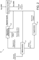
- FIG 2 schematically represents a preferred mode of implementation of the organic waste recovery process according to the invention as well as an installation, referenced 20, designed for this mode of implementation.
- organic waste which may in particular be agricultural waste such as cattle manure, pig slurry or cereal residues, urban waste such as household waste or sludge from wastewater treatment plants, industrial waste such as waste from the agri-food industry, or even a mixture of waste from different origins, are introduced into the methanizer, also called a digester, of a methanization unit 21, in which they are subjected to anaerobic fermentation, typically at a temperature of between 20°C and 60°C, which leads to the formation, on the one hand, of a pasty product which is given the name of methanization digestate and, on the other hand, of a biogas which is essentially composed of CH 4 and CO 2 .
- the methanizer also called a digester
- the methanization digestate once evacuated from the methanizer 21, is directed to a solid/liquid separation unit 22 in which it is separated into a solid digestate and a liquid digestate, for example by means of one or more devices of the screw press, belt press, filter press or centrifuge type.
- the solid digest thus obtained can be sent to a storage unit (not shown in the figure 2 ) for subsequent spreading and/or to a post-treatment unit (not shown in the figure 2 ) of the drying or composting unit type.
- the liquid digestate As for the liquid digestate, it is directed to an installation 23 dedicated to the synthesis of H n -LOHC, which may in particular be an installation of the type shown in the figure. figure 1 .
- the H n -LOHC thus synthesized is then directed to an area dedicated to its conditioning (not shown in the figure 2 ) for its storage and/or transport.
- the biogas produced in the methanizer 21 is directed to a cogeneration unit 24 comprising, for example, a gas turbine coupled to an alternator and a heat recovery unit.
Landscapes
- Chemical & Material Sciences (AREA)
- Organic Chemistry (AREA)
- Engineering & Computer Science (AREA)
- Health & Medical Sciences (AREA)
- Combustion & Propulsion (AREA)
- Inorganic Chemistry (AREA)
- General Health & Medical Sciences (AREA)
- Chemical Kinetics & Catalysis (AREA)
- Organic Low-Molecular-Weight Compounds And Preparation Thereof (AREA)
- Micro-Organisms Or Cultivation Processes Thereof (AREA)
- Processing Of Solid Wastes (AREA)
- Hydrogen, Water And Hydrids (AREA)
- Catalysts (AREA)
Claims (15)
- Verfahren zur Synthese einer mit Wasserstoff beladenen organischen Wasserstoffträgerflüssigkeit, Hn-LOHC, umfassend mindestens die Schritte:a) Herstellen von gasförmigem Ammoniak aus Gärrückständen aus der Biogasanlage;b) Aufteilen des in Schritt a) erzeugten Ammoniakgases in einen ersten und einen zweiten Strom;c) katalytisches Aminieren einer nicht mit Wasserstoff beladenen organischen Wasserstoffträgerflüssigkeit, H0-LOHC, durch Reaktion mit dem Ammoniakgas des ersten Stroms, um das H0-LOHC in ein aminiertes H0-LOHC umzuwandeln und Wasserstoff zu erzeugen;d) katalytisches Aufspalten des Ammoniakgases aus dem zweiten Strom zur Erzeugung von Wasserstoff; unde) katalytisches Hydrieren des in Schritt c) erhaltenen aminierten H0-LOHC durch Umsetzen mit dem in den Schritten c) und d) erzeugten Wasserstoff, wodurch Hn-LOHC erhalten wird.
- Verfahren nach Anspruch 1, wobei der Methanisierungsgärrest ein flüssiger Gärrest ist.
- Verfahren nach Anspruch 2, wobei die Herstellung des Ammoniakgases eine Desorption des in dem flüssigen Gärrest enthaltenen Ammoniumstickstoffs in Form von Ammoniakgas umfasst.
- Verfahren nach Anspruch 3, wobei die Desorption eine Zirkulation des flüssigen Gärrest in einer Füllkörperkolonne im Gegenstrom zu Stickstoff oder einem Gas, das im Wesentlichen aus Stickstoff besteht, umfasst.
- Verfahren nach einem der Ansprüche 1 bis 4, das zusätzlich eine Reinigung des erzeugten gasförmigen Ammoniaks umfasst.
- Verfahren nach einem der Ansprüche 1 bis 5, wobei die katalytische Spaltung von gasförmigem Ammoniak in einem Reaktor durchgeführt wird, der auf eine Temperatur zwischen 450 °C und 800 °C erhitzt wird.
- Verfahren nach einem der Ansprüche 1 bis 6, das zusätzlich eine Reinigung des Wasserstoffs umfasst, der bei der katalytischen Spaltung von gasförmigem Ammoniak entsteht.
- Verfahren nach einem der Ansprüche 1 bis 7, wobei das H0-LOHC eine aromatische oder heteroaromatische, monocyclische oder polycyclische Verbindung ist, die gegebenenfalls mit einer oder mehreren Alkyl-, Aryl-, Heteroaryl-, Arylalkyl- oder Heteroarylalkylgruppen substituiert ist.
- Verfahren nach Anspruch 8, wobei das H0-LOHC Toluol, 2-Benzyltoluol, 4-Benzyltoluol, 2,3-Dibenzyltoluol, 2,4-Dibenzyltoluol, Naphthalin, N-Ethylcarbazol, Indol, 1-Methylindol, 2-Methylindol, 3-Methylindol, 4-Methylindol, 5-Methylindol, 6-Methylindol, 1,2-Dimethylindol, 2,3-Dimethylindol, 2,5-Dimethylindol, Dibenzofuran, Phenazin, 2-(N-Methylbenzyl)pyridin oder 4,4'-Bipiperidin ist.
- Verfahren nach einem der Ansprüche 1 bis 9, wobei die katalytische Aminierung von H0-LOHC in einem Reaktor durchgeführt wird, der auf eine Temperatur zwischen 200 °C und 800 °C und unter einem Druck zwischen 0,1 MPa und 90 MPa erhitzt wird.
- Verfahren nach einem der Ansprüche 1 bis 10, das zusätzlich eine Reinigung des Wasserstoffs umfasst, der durch die katalytische Aminierung von H0-LOHC erzeugt wird.
- Verfahren nach einem der Ansprüche 1 bis 11, wobei die katalytische Hydrierung von aminiertem H0-LOHC bei einem Wasserstoffdruck zwischen 5 MPa und 10 MPa durchgeführt wird.
- Verfahren nach einem der Ansprüche 6 oder 10, wobei der Reaktor mit Wärme und/oder Strom beheizt wird, die/der aus Biogas aus der Methanisierung erzeugt wird/werden.
- Verfahren zur Verwertung von organischen Abfällen, das mindestens die folgenden Schritte umfasst:- Methanisierung von organischen Abfällen, um Gärrückstand und Biogas zu produzieren;- Synthetisieren einer wasserstoffbeladenen organischen Trägerflüssigkeit, bezeichnet als Hn-LOHC, aus dem Gärrest der Methanisierung durch Ausführen eines Verfahrens nach einem der Ansprüche 1 bis 13; und- Erzeugen von Wärme und/oder Strom aus Biogas.
- Verfahren zur Herstellung von Wasserstoff, das mindestens die folgenden Schritte umfasst:- Synthetisieren einer wasserstoffbeladenen organischen Trägerflüssigkeit, die mit Hn-LOHC bezeichnet wird, durch Ausführen eines Verfahrens nach einem der Ansprüche 1 bis 13;- Konditionieren von Hn-LOHC für die Lagerung und/oder den Transport; und- katalytisches Dehydrieren des so konditionierten Hn-LOHC.
Applications Claiming Priority (2)
| Application Number | Priority Date | Filing Date | Title |
|---|---|---|---|
| FR2106270A FR3123910B1 (fr) | 2021-06-14 | 2021-06-14 | Procédé de synthèse d’un liquide organique porteur d’hydrogène (LOHC) chargé en hydrogène utilisant de l’hydrogène produit à partir d’un digestat de méthanisation |
| PCT/FR2022/051090 WO2022263748A1 (fr) | 2021-06-14 | 2022-06-08 | Procédé de synthèse d'un liquide organique porteur d'hydrogène (lohc) chargé en hydrogène utilisant de l'hydrogène produit à partir d'un digestat de méthanisation |
Publications (3)
| Publication Number | Publication Date |
|---|---|
| EP4330184A1 EP4330184A1 (de) | 2024-03-06 |
| EP4330184B1 true EP4330184B1 (de) | 2025-02-12 |
| EP4330184C0 EP4330184C0 (de) | 2025-02-12 |
Family
ID=77821832
Family Applications (1)
| Application Number | Title | Priority Date | Filing Date |
|---|---|---|---|
| EP22735554.2A Active EP4330184B1 (de) | 2021-06-14 | 2022-06-08 | Verfahren zur synthese eines mit wasserstoff beladenen flüssigen organischen wasserstoffträgers (lohc) unter verwendung von aus einem methanisierungsaufschluss erzeugtem wasserstoff |
Country Status (6)
| Country | Link |
|---|---|
| US (1) | US20240228269A9 (de) |
| EP (1) | EP4330184B1 (de) |
| JP (1) | JP2024524078A (de) |
| ES (1) | ES3019132T3 (de) |
| FR (1) | FR3123910B1 (de) |
| WO (1) | WO2022263748A1 (de) |
Families Citing this family (1)
| Publication number | Priority date | Publication date | Assignee | Title |
|---|---|---|---|---|
| DE102023207952A1 (de) * | 2023-08-18 | 2025-02-20 | Hydrogenious Lohc Technologies Gmbh | Anlage und Verfahren zur Herstellung und Verwendung eines flüssigen organischen Wasserstoffträgermediums |
Family Cites Families (3)
| Publication number | Priority date | Publication date | Assignee | Title |
|---|---|---|---|---|
| DE102004062253A1 (de) * | 2004-12-23 | 2006-07-06 | Basf Ag | Direktaminierung von Kohlenwasserstoffen |
| WO2007140441A2 (en) * | 2006-05-31 | 2007-12-06 | The Trustees Of Columbia University In The City Of New York | Methods and systems for generating hydrogen from a biomass |
| US9879828B2 (en) * | 2014-09-03 | 2018-01-30 | Hydrogenious Technologies Gmbh | Arrangement and method for operating hydrogen filling stations |
-
2021
- 2021-06-14 FR FR2106270A patent/FR3123910B1/fr active Active
-
2022
- 2022-06-08 ES ES22735554T patent/ES3019132T3/es active Active
- 2022-06-08 US US18/569,889 patent/US20240228269A9/en active Pending
- 2022-06-08 EP EP22735554.2A patent/EP4330184B1/de active Active
- 2022-06-08 JP JP2023577222A patent/JP2024524078A/ja active Pending
- 2022-06-08 WO PCT/FR2022/051090 patent/WO2022263748A1/fr not_active Ceased
Also Published As
| Publication number | Publication date |
|---|---|
| FR3123910A1 (fr) | 2022-12-16 |
| FR3123910B1 (fr) | 2025-08-29 |
| US20240132343A1 (en) | 2024-04-25 |
| WO2022263748A1 (fr) | 2022-12-22 |
| JP2024524078A (ja) | 2024-07-05 |
| EP4330184C0 (de) | 2025-02-12 |
| US20240228269A9 (en) | 2024-07-11 |
| EP4330184A1 (de) | 2024-03-06 |
| ES3019132T3 (en) | 2025-05-20 |
Similar Documents
| Publication | Publication Date | Title |
|---|---|---|
| CA2792012C (fr) | Procede pour une production d'hydrogene avec emission de co2 reduite | |
| EP1890961B1 (de) | Verfahren zur simultanen erzeugung von wasserstoff und kohlenmonoxyd | |
| FR2805531A1 (fr) | Procede de production d'hydrogene par oxydation partielle d'hydrocarbures | |
| JP2006522588A (ja) | 自給式流線型メタンおよび/または高純度水素生成システム | |
| WO2022229838A1 (en) | Process for producing hydrogen from a hydrocarbon feedstock | |
| EP2931654A1 (de) | Verfahren zur herstellung von wasserstoff durch reformieren von kohlenwasserstoffen mit wasserdampf, kombiniert mit kohlendioxidabscheidung und dampferzeugung | |
| CA2565936A1 (fr) | Procede de production de gaz de synthese a partir de matiere carbonee et d'energie electrique | |
| FR2881417A1 (fr) | Procede de production de gaz de synthese a faible emission de dioxyde de carbone | |
| FR2825995A1 (fr) | Installation et procede de production de gaz de synthese comprenant un reacteur de vaporeformage et un reacteur de conversion du co2 chauffe par un gaz chaud | |
| FR3142477A1 (fr) | Production de carburants de synthèse à partir de CO2 avec oxycombustion partielle de sous-produits et séparation de CO2 | |
| EP4328287A1 (de) | Verfahren zur herstellung von synthetischem kraftstoff | |
| JP2007254180A (ja) | 自立型低級炭化水素直接分解プロセスおよび該プロセスシステム | |
| WO2024110371A1 (fr) | Production de carburants de synthèse à partir de dioxyde de carbone avec séparation de dioxyde de carbone | |
| WO2022263748A1 (fr) | Procédé de synthèse d'un liquide organique porteur d'hydrogène (lohc) chargé en hydrogène utilisant de l'hydrogène produit à partir d'un digestat de méthanisation | |
| FR3142475A1 (fr) | Production de carburants de synthèse à partir de dioxyde de carbone avec oxycombustion partielle ou totale de sous-produits | |
| WO2011148066A2 (fr) | Procédé de production anaérobie d'hydrogène | |
| WO2024110349A1 (fr) | Production de carburants de synthèse à partir de dioxyde de carbone avec combustion à l'air de sous-produits | |
| FR3052919A1 (fr) | Installation et procede de production d'energie comprenant une pile a combustible | |
| EP1575698B1 (de) | Verfahren zur erzeugung von synthesegas mittels katalytischer teiloxidation | |
| FR3137306A1 (fr) | Procédé de conversion du dioxyde de carbone avec production d’hydrogène, de méthane et/ou d’hydrocarbures | |
| JP7482164B2 (ja) | 炭化水素の直接分解方法 | |
| WO2024110402A1 (fr) | Valorisation énergétique pour la production de carburants de synthèse à partir de dioxyde de carbone | |
| EP0318342B1 (de) | Verfahren zur Reformierung unreinen Methanols und Vorrichtung für seine Anwendung | |
| WO2002085782A1 (fr) | Procede d'oxydation partielle catalytique d'hydrocarbures pour la production de gaz de synthese a faible rapport h2/co | |
| US20250296838A1 (en) | Tri-reforming of methane to hydrogen, methods for preparation of the same, and applications therein |
Legal Events
| Date | Code | Title | Description |
|---|---|---|---|
| STAA | Information on the status of an ep patent application or granted ep patent |
Free format text: STATUS: UNKNOWN |
|
| STAA | Information on the status of an ep patent application or granted ep patent |
Free format text: STATUS: THE INTERNATIONAL PUBLICATION HAS BEEN MADE |
|
| PUAI | Public reference made under article 153(3) epc to a published international application that has entered the european phase |
Free format text: ORIGINAL CODE: 0009012 |
|
| STAA | Information on the status of an ep patent application or granted ep patent |
Free format text: STATUS: REQUEST FOR EXAMINATION WAS MADE |
|
| 17P | Request for examination filed |
Effective date: 20231130 |
|
| AK | Designated contracting states |
Kind code of ref document: A1 Designated state(s): AL AT BE BG CH CY CZ DE DK EE ES FI FR GB GR HR HU IE IS IT LI LT LU LV MC MK MT NL NO PL PT RO RS SE SI SK SM TR |
|
| DAV | Request for validation of the european patent (deleted) | ||
| DAX | Request for extension of the european patent (deleted) | ||
| GRAP | Despatch of communication of intention to grant a patent |
Free format text: ORIGINAL CODE: EPIDOSNIGR1 |
|
| STAA | Information on the status of an ep patent application or granted ep patent |
Free format text: STATUS: GRANT OF PATENT IS INTENDED |
|
| RAP3 | Party data changed (applicant data changed or rights of an application transferred) |
Owner name: COMMISSARIAT A L'ENERGIE ATOMIQUE ET AUX ENERGIESALTERNATIVES |
|
| INTG | Intention to grant announced |
Effective date: 20241014 |
|
| RIN1 | Information on inventor provided before grant (corrected) |
Inventor name: DELAHAYE, THIBAUD Inventor name: LETURCQ, GILLES |
|
| GRAS | Grant fee paid |
Free format text: ORIGINAL CODE: EPIDOSNIGR3 |
|
| GRAA | (expected) grant |
Free format text: ORIGINAL CODE: 0009210 |
|
| STAA | Information on the status of an ep patent application or granted ep patent |
Free format text: STATUS: THE PATENT HAS BEEN GRANTED |
|
| AK | Designated contracting states |
Kind code of ref document: B1 Designated state(s): AL AT BE BG CH CY CZ DE DK EE ES FI FR GB GR HR HU IE IS IT LI LT LU LV MC MK MT NL NO PL PT RO RS SE SI SK SM TR |
|
| REG | Reference to a national code |
Ref country code: GB Ref legal event code: FG4D Free format text: NOT ENGLISH |
|
| REG | Reference to a national code |
Ref country code: CH Ref legal event code: EP |
|
| REG | Reference to a national code |
Ref country code: DE Ref legal event code: R096 Ref document number: 602022010584 Country of ref document: DE |
|
| REG | Reference to a national code |
Ref country code: IE Ref legal event code: FG4D Free format text: LANGUAGE OF EP DOCUMENT: FRENCH |
|
| U01 | Request for unitary effect filed |
Effective date: 20250214 |
|
| U07 | Unitary effect registered |
Designated state(s): AT BE BG DE DK EE FI FR IT LT LU LV MT NL PT RO SE SI Effective date: 20250221 |
|
| REG | Reference to a national code |
Ref country code: ES Ref legal event code: FG2A Ref document number: 3019132 Country of ref document: ES Kind code of ref document: T3 Effective date: 20250520 |
|
| PG25 | Lapsed in a contracting state [announced via postgrant information from national office to epo] |
Ref country code: RS Free format text: LAPSE BECAUSE OF FAILURE TO SUBMIT A TRANSLATION OF THE DESCRIPTION OR TO PAY THE FEE WITHIN THE PRESCRIBED TIME-LIMIT Effective date: 20250512 |
|
| PG25 | Lapsed in a contracting state [announced via postgrant information from national office to epo] |
Ref country code: PL Free format text: LAPSE BECAUSE OF FAILURE TO SUBMIT A TRANSLATION OF THE DESCRIPTION OR TO PAY THE FEE WITHIN THE PRESCRIBED TIME-LIMIT Effective date: 20250212 |
|
| PG25 | Lapsed in a contracting state [announced via postgrant information from national office to epo] |
Ref country code: NO Free format text: LAPSE BECAUSE OF FAILURE TO SUBMIT A TRANSLATION OF THE DESCRIPTION OR TO PAY THE FEE WITHIN THE PRESCRIBED TIME-LIMIT Effective date: 20250512 Ref country code: IS Free format text: LAPSE BECAUSE OF FAILURE TO SUBMIT A TRANSLATION OF THE DESCRIPTION OR TO PAY THE FEE WITHIN THE PRESCRIBED TIME-LIMIT Effective date: 20250612 |
|
| PG25 | Lapsed in a contracting state [announced via postgrant information from national office to epo] |
Ref country code: HR Free format text: LAPSE BECAUSE OF FAILURE TO SUBMIT A TRANSLATION OF THE DESCRIPTION OR TO PAY THE FEE WITHIN THE PRESCRIBED TIME-LIMIT Effective date: 20250212 |
|
| PG25 | Lapsed in a contracting state [announced via postgrant information from national office to epo] |
Ref country code: GR Free format text: LAPSE BECAUSE OF FAILURE TO SUBMIT A TRANSLATION OF THE DESCRIPTION OR TO PAY THE FEE WITHIN THE PRESCRIBED TIME-LIMIT Effective date: 20250513 |
|
| U20 | Renewal fee for the european patent with unitary effect paid |
Year of fee payment: 4 Effective date: 20250627 |
|
| PG25 | Lapsed in a contracting state [announced via postgrant information from national office to epo] |
Ref country code: SM Free format text: LAPSE BECAUSE OF FAILURE TO SUBMIT A TRANSLATION OF THE DESCRIPTION OR TO PAY THE FEE WITHIN THE PRESCRIBED TIME-LIMIT Effective date: 20250212 |
|
| PGFP | Annual fee paid to national office [announced via postgrant information from national office to epo] |
Ref country code: ES Payment date: 20250718 Year of fee payment: 4 |
|
| PG25 | Lapsed in a contracting state [announced via postgrant information from national office to epo] |
Ref country code: CZ Free format text: LAPSE BECAUSE OF FAILURE TO SUBMIT A TRANSLATION OF THE DESCRIPTION OR TO PAY THE FEE WITHIN THE PRESCRIBED TIME-LIMIT Effective date: 20250212 |
|
| PG25 | Lapsed in a contracting state [announced via postgrant information from national office to epo] |
Ref country code: SK Free format text: LAPSE BECAUSE OF FAILURE TO SUBMIT A TRANSLATION OF THE DESCRIPTION OR TO PAY THE FEE WITHIN THE PRESCRIBED TIME-LIMIT Effective date: 20250212 |
|
| U1N | Appointed representative for the unitary patent procedure changed after the registration of the unitary effect |
Representative=s name: SANTARELLI; FR |
|
| PLBE | No opposition filed within time limit |
Free format text: ORIGINAL CODE: 0009261 |
|
| STAA | Information on the status of an ep patent application or granted ep patent |
Free format text: STATUS: NO OPPOSITION FILED WITHIN TIME LIMIT |
|
| REG | Reference to a national code |
Ref country code: CH Ref legal event code: L10 Free format text: ST27 STATUS EVENT CODE: U-0-0-L10-L00 (AS PROVIDED BY THE NATIONAL OFFICE) Effective date: 20251224 |
|
| 26N | No opposition filed |
Effective date: 20251113 |
|
| REG | Reference to a national code |
Ref country code: CH Ref legal event code: H13 Free format text: ST27 STATUS EVENT CODE: U-0-0-H10-H13 (AS PROVIDED BY THE NATIONAL OFFICE) Effective date: 20260127 |
|
| PG25 | Lapsed in a contracting state [announced via postgrant information from national office to epo] |
Ref country code: MC Free format text: LAPSE BECAUSE OF FAILURE TO SUBMIT A TRANSLATION OF THE DESCRIPTION OR TO PAY THE FEE WITHIN THE PRESCRIBED TIME-LIMIT Effective date: 20250212 |
|
| PG25 | Lapsed in a contracting state [announced via postgrant information from national office to epo] |
Ref country code: IE Free format text: LAPSE BECAUSE OF NON-PAYMENT OF DUE FEES Effective date: 20250608 |
|
| PG25 | Lapsed in a contracting state [announced via postgrant information from national office to epo] |
Ref country code: CH Free format text: LAPSE BECAUSE OF NON-PAYMENT OF DUE FEES Effective date: 20250630 |
|
| PGFP | Annual fee paid to national office [announced via postgrant information from national office to epo] |
Ref country code: GB Payment date: 20260623 Year of fee payment: 5 |
|
| U20 | Renewal fee for the european patent with unitary effect paid |
Year of fee payment: 5 Effective date: 20260626 |
|
| PG25 | Lapsed in a contracting state [announced via postgrant information from national office to epo] |
Ref country code: CY Free format text: LAPSE BECAUSE OF FAILURE TO SUBMIT A TRANSLATION OF THE DESCRIPTION OR TO PAY THE FEE WITHIN THE PRESCRIBED TIME-LIMIT Effective date: 20250212 |