EP4331002B1 - Système de cathode creuse pour générer un plasma et procédé de fonctionnement d'un tel système de cathode creuse - Google Patents
Système de cathode creuse pour générer un plasma et procédé de fonctionnement d'un tel système de cathode creuse Download PDFInfo
- Publication number
- EP4331002B1 EP4331002B1 EP22716911.7A EP22716911A EP4331002B1 EP 4331002 B1 EP4331002 B1 EP 4331002B1 EP 22716911 A EP22716911 A EP 22716911A EP 4331002 B1 EP4331002 B1 EP 4331002B1
- Authority
- EP
- European Patent Office
- Prior art keywords
- cathode
- cathode tube
- tubes
- tube
- hollow
- Prior art date
- Legal status (The legal status is an assumption and is not a legal conclusion. Google has not performed a legal analysis and makes no representation as to the accuracy of the status listed.)
- Active
Links
Images


Classifications
-
- C—CHEMISTRY; METALLURGY
- C23—COATING METALLIC MATERIAL; COATING MATERIAL WITH METALLIC MATERIAL; CHEMICAL SURFACE TREATMENT; DIFFUSION TREATMENT OF METALLIC MATERIAL; COATING BY VACUUM EVAPORATION, BY SPUTTERING, BY ION IMPLANTATION OR BY CHEMICAL VAPOUR DEPOSITION, IN GENERAL; INHIBITING CORROSION OF METALLIC MATERIAL OR INCRUSTATION IN GENERAL
- C23C—COATING METALLIC MATERIAL; COATING MATERIAL WITH METALLIC MATERIAL; SURFACE TREATMENT OF METALLIC MATERIAL BY DIFFUSION INTO THE SURFACE, BY CHEMICAL CONVERSION OR SUBSTITUTION; COATING BY VACUUM EVAPORATION, BY SPUTTERING, BY ION IMPLANTATION OR BY CHEMICAL VAPOUR DEPOSITION, IN GENERAL
- C23C14/00—Coating by vacuum evaporation, by sputtering or by ion implantation of the coating forming material
- C23C14/22—Coating by vacuum evaporation, by sputtering or by ion implantation of the coating forming material characterised by the process of coating
- C23C14/34—Sputtering
- C23C14/3407—Cathode assembly for sputtering apparatus, e.g. Target
-
- C—CHEMISTRY; METALLURGY
- C23—COATING METALLIC MATERIAL; COATING MATERIAL WITH METALLIC MATERIAL; CHEMICAL SURFACE TREATMENT; DIFFUSION TREATMENT OF METALLIC MATERIAL; COATING BY VACUUM EVAPORATION, BY SPUTTERING, BY ION IMPLANTATION OR BY CHEMICAL VAPOUR DEPOSITION, IN GENERAL; INHIBITING CORROSION OF METALLIC MATERIAL OR INCRUSTATION IN GENERAL
- C23C—COATING METALLIC MATERIAL; COATING MATERIAL WITH METALLIC MATERIAL; SURFACE TREATMENT OF METALLIC MATERIAL BY DIFFUSION INTO THE SURFACE, BY CHEMICAL CONVERSION OR SUBSTITUTION; COATING BY VACUUM EVAPORATION, BY SPUTTERING, BY ION IMPLANTATION OR BY CHEMICAL VAPOUR DEPOSITION, IN GENERAL
- C23C14/00—Coating by vacuum evaporation, by sputtering or by ion implantation of the coating forming material
- C23C14/22—Coating by vacuum evaporation, by sputtering or by ion implantation of the coating forming material characterised by the process of coating
- C23C14/54—Controlling or regulating the coating process
-
- H—ELECTRICITY
- H01—ELECTRIC ELEMENTS
- H01J—ELECTRIC DISCHARGE TUBES OR DISCHARGE LAMPS
- H01J37/00—Discharge tubes with provision for introducing objects or material to be exposed to the discharge, e.g. for the purpose of examination or processing thereof
- H01J37/32—Gas-filled discharge tubes
- H01J37/32009—Arrangements for generation of plasma specially adapted for examination or treatment of objects, e.g. plasma sources
- H01J37/32055—Arc discharge
-
- H—ELECTRICITY
- H01—ELECTRIC ELEMENTS
- H01J—ELECTRIC DISCHARGE TUBES OR DISCHARGE LAMPS
- H01J37/00—Discharge tubes with provision for introducing objects or material to be exposed to the discharge, e.g. for the purpose of examination or processing thereof
- H01J37/32—Gas-filled discharge tubes
- H01J37/32431—Constructional details of the reactor
- H01J37/3244—Gas supply means
-
- H—ELECTRICITY
- H01—ELECTRIC ELEMENTS
- H01J—ELECTRIC DISCHARGE TUBES OR DISCHARGE LAMPS
- H01J37/00—Discharge tubes with provision for introducing objects or material to be exposed to the discharge, e.g. for the purpose of examination or processing thereof
- H01J37/32—Gas-filled discharge tubes
- H01J37/32431—Constructional details of the reactor
- H01J37/32532—Electrodes
- H01J37/32596—Hollow cathodes
-
- H—ELECTRICITY
- H05—ELECTRIC TECHNIQUES NOT OTHERWISE PROVIDED FOR
- H05H—PLASMA TECHNIQUE; PRODUCTION OF ACCELERATED ELECTRICALLY-CHARGED PARTICLES OR OF NEUTRONS; PRODUCTION OR ACCELERATION OF NEUTRAL MOLECULAR OR ATOMIC BEAMS
- H05H1/00—Generating plasma; Handling plasma
- H05H1/24—Generating plasma
- H05H1/48—Generating plasma using an arc
- H05H1/481—Hollow cathodes
-
- H—ELECTRICITY
- H01—ELECTRIC ELEMENTS
- H01J—ELECTRIC DISCHARGE TUBES OR DISCHARGE LAMPS
- H01J2237/00—Discharge tubes exposing object to beam, e.g. for analysis treatment, etching, imaging
- H01J2237/32—Processing objects by plasma generation
- H01J2237/33—Processing objects by plasma generation characterised by the type of processing
- H01J2237/332—Coating
Definitions
- the invention relates to a hollow cathode system for generating a plasma, which is used, for example, in coating or processing substrate surfaces under vacuum conditions, and to a method for operating such a hollow cathode system.
- Hollow cathode plasma sources are used for a variety of tasks, such as plasma activation in PVD processes, excitation of PECVD processes, decoating, cleaning, or physico-chemical modification of surfaces, the implementation of arc evaporators, or as a heating source.
- the functional principle of a hollow cathode discharge consists in particularly efficient plasma excitation between mutually inclined cathode surfaces, the space between which is flowed through by a working gas ( DE 10 2010 011 592 A1 and DE 10 2013 210155 A1 ).
- Ions from the plasma zone impact the inner wall of the cathode and thus ensure the provision of electrons for the discharge via secondary electron emission (hollow cathode glow discharge) or via thermionic electron emission (hollow cathode arc discharge), which, however, are associated with different wear mechanisms.
- the ion bombardment ensures the continuous atomization of hollow cathodes (sputtering effect).
- arc discharge in which the hollow cathodes are typically tubular, the high operating temperatures result in increased sputtering rates, evaporation, recrystallization and embrittlement of material, as well as chemically assisted removal in reactive processes during operation.
- the ignition phase is particularly prone to wear, as material splashing due to cold arcs often occurs.
- the service life of such plasma sources is therefore only a few hours (depending on the operating characteristics and process conditions). This is far too short for industrially standard continuous operation over one, sometimes even two weeks.
- the short cathode lifetime means a significant loss of time, as replacing the wear parts requires interrupting the process and venting the process chamber (contaminating the process environment), which also necessitates subsequent reconditioning. Storing multiple complete plasma sources and decoupling them from the process chamber using vacuum technology is a major challenge. Process space through slide valves would be extremely complex and costly and therefore does not represent an economical option.
- the discharge current in a hollow-cathode arc discharge is limited by the maximum achievable emission current density of the hollow cathode material before reaching its melting temperature, as well as by the limited emission area – the discharge is concentrated in a so-called active zone, i.e., a specific axial region of the hollow cathode where the working gas pressure and the free path lengths of the plasma electrons are well matched. Therefore, a significant increase in discharge power cannot generally be achieved by increasing the load on a hollow cathode source, but only through the costly implementation of several plasma sources operating in parallel.
- a hollow cathode system is known in which a cathode tube is enclosed, at least at the end of the gas outlet opening, by an annular anode and an annular magnetic coil.
- a higher plasma intensity can be achieved compared to conventional hollow cathode plasma sources.
- WO 2013/091927 A1 discloses plasma sources comprising two hollow cathodes, the outlet openings of the two hollow cathodes facing each other.
- a power supply device is connected between the two hollow cathodes, providing an alternating voltage so that the two hollow cathodes alternately function as the cathode and anode of a hollow cathode arc discharge.
- a third problem with hollow cathode systems is the immense material expenditure for the wear parts. Hollow cathodes, which require frequent replacement, are always replaced as a whole, even though wear is essentially concentrated only in the active zone.
- the invention is therefore based on the technical problem of creating a hollow cathode system for generating a plasma and a method for operating such a hollow cathode system, by means of which the disadvantages of the prior art can be overcome.
- a hollow cathode system according to the invention and by means of a method according to the invention, it should be possible to enable a longer operating time compared to the prior art.
- a hollow cathode system according to the invention and by means of a method according to the invention it should be possible to change the intensity of a plasma generated by means of a hollow cathode system according to the invention.
- An electrically conductive contact between the individual cathode tubes can be formed, for example, by means of contact elements or, if the cathode tubes are arranged adjacent to one another, also by physical contact. All cathode tubes of a hollow cathode system according to the invention thus always have the same electrical potential. Furthermore, in a hollow cathode system according to the invention, each cathode tube is assigned a separate actuator, by means of which the amount of gas provided in the first gas reservoir and/or the type of gas flowing through the cathode tube assigned to the actuator can be adjusted.
- auxiliary devices are usually used to ignite a hollow cathode, such as a heating coil wound around a hollow cathode and connected to an associated power supply device for providing an electrical heating voltage.
- auxiliary devices can also include magnetic field coils or permanent magnets for generating a magnetic field in and around a hollow cathode, or a device for generating high-voltage pulses between the hollow cathode and the anode device.
- Such an auxiliary device for igniting an arc discharge can also be assigned to each cathode tube of a hollow cathode system according to the invention. Any auxiliary device that is also used in the prior art for igniting a hollow cathode arc discharge can be used.
- the tube axes of the at least two cathode tubes are aligned parallel to each other or have an angle of at most 5° to each other, with the gas from the gas reservoir flowing through the at least two cathode tubes in the same gas flow direction.
- cathode tubes are spaced at a maximum distance of 20 mm from each other.
- a method for operating a hollow cathode system in which an anode device, a power supply device for providing an electrical voltage connected between the cathode tube and the anode device and at least one first gas reservoir for providing a gas flowing through the cathode tube are used, is characterized in that at least two cathode tubes are used which are electrically conductively connected to one another and wherein each cathode tube is assigned a separate actuator by means of which the quantity and/or the type of gas flowing through the cathode tube assigned to the respective actuator is adjusted.
- a hollow cathode system can essentially be operated in two modes.
- a first operating mode an arc discharge is ignited by means of at least one first cathode tube and maintained until, for example, the service life of the at least one first cathode tube has expired.
- a first gas quantity flowing through at least the first cathode tube is adjusted by means of a first actuator, which is suitable for igniting and maintaining an arc discharge between the first cathode tube and the anode device.
- a hollow cathode system according to the invention can be extended compared to the prior art, in which a vacuum chamber must be opened and the hollow cathode replaced after wear of a hollow cathode.
- an arc discharge is ignited once in a cathode tube and maintained until the operating time of the cathode tube has expired.
- the cathode tubes involved can also be activated alternately, one after the other, in partial cycles with respect to their service life. so that all cathode tubes involved always have approximately the same level of wear, which has a positive effect on maintaining homogeneous process conditions.
- the second operating mode of a hollow cathode system according to the invention is primarily not about extending its operating life, but about changing the intensity of a plasma generated by the hollow cathode system. It has already been explained that the plasmas of the individual cathode tubes of a hollow cathode system according to the invention penetrate essentially the same volume within a vacuum chamber. By additionally activating a second cathode tube when at least one arc discharge is already burning from a first cathode tube, or by deactivating a second cathode tube when an arc discharge is burning from at least a first and a second cathode tube, the intensity of the plasma in the volume penetrated by the plasma can be changed. In the second operating mode, an arc discharge is maintained at least temporarily from at least two cathode tubes simultaneously towards the anode device in order to form a stronger plasma compared to the case where an arc discharge burns from only one cathode tube.
- FIG. 1 A hollow cathode system 10 according to the invention is shown schematically.
- the hollow cathode system 10 comprises a first cathode tube 11a and a second cathode tube 11b, which are spaced apart by a maximum of 20 mm.
- the tube axes 12a and 12b of the two cathode tubes 11a and 11b are aligned parallel to each other.
- the hollow cathode system 10 further includes an anode device 13 and a power supply device 14, which provides an electrical voltage for forming an arc discharge between the first cathode tube 11a and/or the second cathode tube 11b on one side and the anode device 13 on the other side.
- the two cathode tubes 11a and 11b and the anode device 13 are arranged within a vacuum chamber, which, for reasons of clarity, is not shown in Fig. 1 is shown.
- a working gas flows in the same flow direction through the first cathode tube 11a and/or through the second cathode tube, with the working gas being provided in a first gas reservoir 15 and being guided from the gas reservoir to the cathode tubes 11a and 11b via gas lines 16.
- a first actuator 17a is assigned to the first cathode tube 11a
- a second actuator 17b is assigned to the second cathode tube 11b.
- the amount of gas flowing through a cathode tube assigned to a respective actuator can be separately adjusted using the actuators 17a and 17b.
- the two cathode tubes 11a and 11b are electrically conductively connected to one another by means of a contact element 18 and thus constantly have the same electrical voltage potential.
- the contact element 18 can, for example, also be designed as a base element made of an electrically conductive material into which the cathode tubes 11a and 11b are screwed.
- the contact element 18 can be omitted if the two cathode tubes 11a and 11b are arranged so closely next to one another that at least a permanent contact is formed between the two cathode tubes.
- an arc discharge can thus be formed in the hollow cathode system 10, starting from each of the two cathode tubes 11a and 11b, towards the anode device 13.
- a gas quantity flowing through the first cathode tube 11a is initially adjusted by means of the first actuator 17a, which gas quantity is suitable for forming an arc discharge between the first cathode tube 11a and the anode device 13.
- an arc discharge is ignited and maintained between the first cathode tube 11a and the anode device 13.
- a cathode tube which is involved in forming an arc discharge involved is also referred to below as an activated cathode tube. If, as previously explained, an arc discharge is formed from the first cathode tube 11a to the anode device 13, initially only the cathode tube 11a is an activated cathode tube, while cathode tube 11b is inactive.
- One or more substrates arranged in the vacuum chamber can thus initially be processed with the assistance of the plasma generated by the first cathode tube 11a.
- the arc discharge between the first cathode tube 11a and the anode device 13 is first extinguished.
- the second actuator 17b is used to adjust the amount of gas flowing through the second cathode tube 11b, which is suitable for forming an arc discharge between the second cathode tube 11b and the anode device 13.
- a corresponding arc discharge is ignited and maintained, so that the processing of one or more substrates within the vacuum chamber can be continued with the assistance of the plasma generated by the second cathode tube 11b.
- the cathode tubes 11a and 11b can also be activated alternately, one after the other, in partial cycles, so that the cathode tubes 11a and 11b always have approximately the same level of wear.
- a second cathode tube is only activated after a first cathode tube has been deactivated.
- a second cathode tube can also be activated before or with the deactivation of a first cathode tube.
- a gas quantity flowing through the first cathode tube 11a is initially adjusted by means of the first actuator 17a, which is suitable for forming an arc discharge between the first cathode tube 11a and the anode device 13.
- the first actuator 17a which is suitable for forming an arc discharge between the first cathode tube 11a and the anode device 13.
- the current intensity for maintaining a respective arc discharge can be adjusted separately for each cathode tube. Since the plasma clouds of the two cathode tubes 11a and 11b at least partially penetrate each other due to their close proximity, an overall plasma with higher power can be generated. If a plasma with lower power is required at a later time, the arc discharge can be extinguished by one of the two cathode tubes 11a and 11b activated at that time.
- the cathode tube configuration comprises a total of two cathode tubes.
- a hollow cathode system according to the invention can also use a cathode tube configuration that comprises more than just two cathode tubes.
- the only essential aspect of the invention is that the cathode tubes are electrically conductively connected to one another and that directly adjacent cathode tubes are spaced apart by a maximum of 20 mm.
- FIG. 2a An exemplary cathode tube configuration 20 according to the invention is shown schematically in cross section, which has three cathode tubes 21a to 21c.
- the cathode tubes 21a to 21c are electrically conductively connected to one another by means of contact elements 28a to 28c.
- contact elements 28a to 28c As already described for the device 10 of Fig. 1
- each of the cathode tubes 21a to 21c is assigned a separate actuator, with which the gas flow through an associated cathode tube can be separately regulated.
- an arc discharge can also be formed separately from each of the cathode tubes 21a to 21c towards an anode device, so that a hollow cathode system according to the invention with a cathode tube configuration 20 can also be operated in the two process variants described above for the embodiment according to Fig. 1
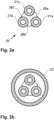
- Fig. 2b is the one from Fig. 2a known cathode tube configuration 20 is shown schematically in cross section. In the embodiment according to Fig.
- the cathode tube configuration 20 is enclosed, at least at the end of the cathode tubes at which the outlet opening of the cathode tubes is located, by an annular element 23 of the anode device associated with the cathode tubes.
- annular anode By means of such a arranged annular anode, a cathode tube of a hollow cathode system according to the invention can also be operated with the methods as described, for example, in DE 10 2006 027 853 A1 are described.
- An annular element 23 of an anode device can also be used in all cathode tube configurations described above and below, wherein the annular element encloses all cathode tubes of a cathode tube configuration, at least at the end of the cathode tubes at which the gas outlet opening of the cathode tubes is located.
- the cathode tubes of a hollow cathode system according to the invention are designed as separate tubes which are electrically connected to one another by means of contact elements.
- Fig. 3 A cathode tube configuration 30 is shown schematically in cross-section, in which a total of four cylindrical recesses 31a to 31d extend through a block 38 made of an electrically conductive material and extend through the entire length of the block 38.
- the four recesses 31a to 31d, with their cylindrical outer surfaces of the block 38, function as cathode tubes through which a working gas flows to form an arc discharge.
- Each recess 31a to 31d is assigned a separate actuator, with which the gas flow through an associated recess can be separately regulated.
- hollow cathode systems typically include auxiliary devices, such as a heating coil with an associated power supply device, by means of which an arc discharge can be ignited in a cathode tube.
- auxiliary devices such as a heating coil with an associated power supply device, by means of which an arc discharge can be ignited in a cathode tube.
- an auxiliary device for igniting an arc discharge can also be associated with the cathode tubes.
- a separate heating coil is wound around each cathode tube or a separate heating element is assigned to each cathode tube.
- a heating coil can be wound around block 38.
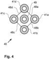
- a cathode tube configuration 40 is shown schematically in cross section, which comprises four cathode tubes 41a to 41d, which are connected by means of Contact elements 48a to 48d are electrically conductively connected to one another.
- a plasma can be generated within a vacuum chamber in accordance with the procedures described above, by means of which plasma at least one substrate can be processed within the vacuum chamber.
- a further cathode tube 49 is arranged, which is electrically insulated from the four cathode tubes 41a to 41d and to which a separate power supply device for forming an arc discharge is assigned.
- a hollow cathode system which comprises the cathode tube configuration 40
- an arc discharge is first ignited by the cathode tube 49, thereby generating a plasma.
- the plasma generated by cathode tube 49 is formed with a lower intensity than the plasmas that can be formed by cathode tubes 41a to 41d.
- the plasma generated by cathode tube 49 is not primarily involved in processing a substrate, but rather serves primarily to provide charge carriers in the space between the cathode tubes and the anode device, which facilitate the ignition of at least one of the cathode tubes 41a to 41d.
- the cathode tube 49 is also subject to less wear than the cathode tubes 41a to 41d. Therefore, the cathode tube 49 can be used to maintain an arc discharge throughout the entire operating time of a hollow cathode system according to the invention with a cathode tube configuration 40, while the cathode tubes 41a to 41d are activated successively or alternately.
- At least two cathode tubes are involved, in which, for example, at least one first cathode tube can be activated during operation of the hollow cathode system, while at least one second cathode tube is inactive.
- at least one first cathode tube can be activated during operation of the hollow cathode system
- at least one second cathode tube is inactive.
- either no gas can flow through the second cathode tube, or a small amount of gas can flow through the second cathode tube, which is not suitable for forming an arc discharge between the second cathode tube and the associated anode device.
- the flow through the second cathode tube with A small amount of gas compared to the amount of gas required to form an arc discharge serves to purge the second cathode tube so that the second cathode tube does not become clogged with particles which, for example, are dusted off by the activated first cathode tube or which may originate from a coating material for coating a substrate within the vacuum chamber.
- the purge gas for a non-activated cathode tube can be, for example, the working gas provided in the first gas reservoir, which also flows through a cathode tube to form an arc discharge.
- another gas preferably an inert gas, which is provided in a second gas reservoir, can also be used to purge a cathode tube.
- the type of gas flowing through each cathode tube can be adjusted, for example, using the same actuator that also adjusts the gas flow rate through each cathode tube.
- the type of gas flowing through each cathode tube can also be adjusted using a separate actuator.
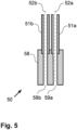
- FIG. 5 A cathode tube configuration 50 is shown schematically in a longitudinal section, which forms a hybrid of separate cathode tubes and recesses in a material block.
- the cathode tube configuration 50 comprises a base element 58 made of an electrically conductive material, in which two cylindrical recesses 59a and 59b have been machined, extending through the entire length of the base element 58.
- the recesses 59a and 59b do not extend over the entire length required for a cathode tube.
- cathode tube sub-elements 51a and 51b are also attached to the base element 58, preferably by means of a detachable connection, such that the tube axis 52a of the cathode tube sub-element 51a and the cylinder axis of the cylindrical recess 59a are identical, and the tube axis 52b of the cathode tube sub-element 51b and the cylinder axis of the cylindrical recess 59b are identical.
- the cylinder axis of a recess and the tube axis of an associated cathode tube sub-element have an offset, for example, to refract any type of radiation from the interior of the vacuum chamber.
- the cathode tube sub-elements 51a and 51b can, for example, have an external thread that is screwed into the base element 58.
- the recess 59a and the associated cathode tube sub-element 51a form a first cathode tube
- the recess 59b and the associated cathode tube sub-element 51b form a second cathode tube.
- the cathode tube configuration 50 comprises only two cathode tubes by way of example, but can also comprise more than just two cathode tubes in alternative embodiments.
Landscapes
- Chemical & Material Sciences (AREA)
- Engineering & Computer Science (AREA)
- Plasma & Fusion (AREA)
- Physics & Mathematics (AREA)
- Analytical Chemistry (AREA)
- Metallurgy (AREA)
- Chemical Kinetics & Catalysis (AREA)
- Materials Engineering (AREA)
- Mechanical Engineering (AREA)
- Organic Chemistry (AREA)
- Spectroscopy & Molecular Physics (AREA)
- Plasma Technology (AREA)
- Physical Vapour Deposition (AREA)
Claims (11)
- Système à cathodes creuses pour la production d'un plasma, comprenant au moins deux tubes formant cathodes (11a ; 11b), un dispositif formant anode (13), un dispositif d'alimentation en courant (14), pour fournir une tension électrique appliquée entre les tubes formant cathodes (11a ; 11b) et le dispositif formant anode (13), et au moins un réservoir de gaz (15) pour fournir un gaz qui traverse les tubes formant cathodes (11a ; 11b), et un organe de réglage séparé (17a ; 17b) étant associé à chaque tube formant cathode (11a ; 11b), au moyen duquel la quantité de gaz qui traverse le tube formant cathode (11a ; 11b) associé à l'organe de réglage (17a ; 17b) est apte à être réglée, caractérisé en ce que lesdits au moins deux tubes formant cathodes (11a ; 11b) sont reliés entre eux de manière électriquement conductrice.
- Système à cathodes creuses selon la revendication 1, dans lequel les axes de tubes (12a ; 12b) desdits au moins deux tubes formant cathodes (11a ; 11b) sont orientés parallèlement l'un à l'autre ou forment entre eux un angle de 5° au maximum.
- Système à cathodes creuses selon la revendication 1 ou la revendication 2, dans lequel la direction du flux de gaz à travers lesdits au moins deux tubes formant cathodes (11a ; 11b) est la même.
- Système à cathodes creuses selon l'une des revendications précédentes, dans lequel des tubes formant cathodes (11a ; 11b) voisins présentent une distance de 20mm maximum les uns par rapport aux autres.
- Système à cathodes creuses selon l'une des revendications précédentes, dans lequel au moins un élément (23) du dispositif formant anode est de forme annulaire, ledit au moins un élément (23) du dispositif formant anode entourant lesdits au moins deux tubes formant cathodes (21a ; 21b ; 21c).
- Procédé pour faire fonctionner un système à cathodes creuses, dans lequel sont utilisés un dispositif d'anode (13), un dispositif d'alimentation en courant (14), pour fournir une tension électrique appliquée entre au moins deux tubes formant cathodes (11a ; 11b) et le dispositif d'anode (13), et au moins un réservoir de gaz (15) pour fournir un courant électrique aux tubes formant cathodes (11a ; 11b), un organe de réglage séparé (17a ; 17b) étant associé à chaque tube formant cathode (11a ; 11b), au moyen duquel la quantité et/ou le type de gaz qui traverse le tube formant cathode (11a ; 11b) associé à l'organe de réglage respectif (17a ; 17b) est réglé, caractérisé en ce que lesdits au moins deux tubes formant cathodes (11a ; 11b) sont reliés entre eux de manière électriquement conductrice.
- Procédé selon la revendication 6, dans lequel, au moins pour un premier tube formant cathode (11a), il est réglé, au moyen d'un premier organe de réglage (17a), une première quantité de gaz traversant le premier tube formant cathode (11a), qui est appropriée pour amorcer une décharge d'arc entre le premier tube formant cathode (11a) et le dispositif formant anode (13).
- Procédé selon la revendication 7, dans lequel, au moins pour un deuxième tube formant cathode, il est réglé, au moyen d'un deuxième organe de réglage, une deuxième quantité de gaz traversant le deuxième tube formant cathode, qui n'est pas appropriée pour amorcer une décharge d'arc entre le deuxième tube formant cathode et le dispositif formant anode.
- Procédé selon la revendication 6, dans lequel, au moins dans un premier tube formant cathode (11a), dans lequel une décharge d'arc est formée entre le premier tube formant cathode (11a) et le dispositif formant anode (13), la décharge d'arc est arrêtée, et, au moins dans un deuxième tube formant cathode (11b), dans lequel aucune décharge d'arc n'est formée entre le deuxième tube formant cathode (11b) et le dispositif formant anode (13), une décharge d'arc est amorcée.
- Procédé selon l'une des revendications 7 à 9, dans lequel une décharge en arc, dont l'intensité de courant est réglable séparément pour chaque tube formant cathode, est entretenue simultanément par au moins deux tubes formant cathodes (11a ; 11b) en direction du dispositif formant anode (13).
- Procédé selon la revendication 6, dans lequel, au moyen des organes de réglage séparés (17a ; 17b), il est réglé également le type de gaz qui traverse le tube formant cathode (11a ; 11b) associé à l'organe de réglage respectif (17a ; 17b).
Applications Claiming Priority (2)
| Application Number | Priority Date | Filing Date | Title |
|---|---|---|---|
| DE102021111097.1A DE102021111097B4 (de) | 2021-04-29 | 2021-04-29 | Hohlkathodensystem zum Erzeugen eines Plasmas und Verfahren zum Betreiben eines solchen Hohlkathodensystems |
| PCT/EP2022/057255 WO2022228778A1 (fr) | 2021-04-29 | 2022-03-18 | Système de cathode creuse pour générer un plasma et procédé de fonctionnement d'un tel système de cathode creuse |
Publications (2)
| Publication Number | Publication Date |
|---|---|
| EP4331002A1 EP4331002A1 (fr) | 2024-03-06 |
| EP4331002B1 true EP4331002B1 (fr) | 2025-04-30 |
Family
ID=81326704
Family Applications (1)
| Application Number | Title | Priority Date | Filing Date |
|---|---|---|---|
| EP22716911.7A Active EP4331002B1 (fr) | 2021-04-29 | 2022-03-18 | Système de cathode creuse pour générer un plasma et procédé de fonctionnement d'un tel système de cathode creuse |
Country Status (6)
| Country | Link |
|---|---|
| US (1) | US12580161B2 (fr) |
| EP (1) | EP4331002B1 (fr) |
| JP (1) | JP7775334B2 (fr) |
| DE (1) | DE102021111097B4 (fr) |
| PL (1) | PL4331002T3 (fr) |
| WO (1) | WO2022228778A1 (fr) |
Citations (3)
| Publication number | Priority date | Publication date | Assignee | Title |
|---|---|---|---|---|
| DE19958016A1 (de) * | 1998-12-02 | 2000-12-14 | Stefan Laure | Plasmagenerator |
| WO2010099218A1 (fr) * | 2009-02-24 | 2010-09-02 | University Of Virginia Patent Foundation | Dépôt en phase vapeur dirigé assisté par plasma à cathode coaxiale creuse et procédé associé |
| DE102013106315A1 (de) * | 2013-06-18 | 2014-12-18 | Fraunhofer-Gesellschaft zur Förderung der angewandten Forschung e.V. | Verfahren und Vorrichtung zum Erzeugen eines physikalischen Plasmas |
Family Cites Families (13)
| Publication number | Priority date | Publication date | Assignee | Title |
|---|---|---|---|---|
| DE19902146C2 (de) * | 1999-01-20 | 2003-07-31 | Fraunhofer Ges Forschung | Verfahren und Einrichtung zur gepulsten Plasmaaktivierung |
| SE516336C2 (sv) * | 1999-04-28 | 2001-12-17 | Hana Barankova | Apparat för plasmabehandling av ytor |
| US6528947B1 (en) * | 1999-12-06 | 2003-03-04 | E. I. Du Pont De Nemours And Company | Hollow cathode array for plasma generation |
| JP3574118B2 (ja) * | 2002-04-24 | 2004-10-06 | 三容真空工業株式会社 | プラズマ発生装置 |
| DE102006027853B4 (de) | 2006-06-16 | 2012-06-14 | Fraunhofer-Gesellschaft zur Förderung der angewandten Forschung e.V. | Verfahren und Vorrichtung zum Erzeugen eines Plasmas sowie Verwendung derselben |
| CA2695902C (fr) * | 2007-08-06 | 2016-01-05 | Plasma Surgical Investments Limited | Ensemble cathodique et procede de generation de plasma pulse |
| DE102010011592A1 (de) | 2010-03-16 | 2011-09-22 | Fraunhofer-Gesellschaft zur Förderung der angewandten Forschung e.V. | Hohlkathoden-Plasmaquelle sowie Verwendung der Hohlkathoden-Plasmaquelle |
| US9443703B2 (en) | 2011-12-19 | 2016-09-13 | Fraunhofer-Gesellschaft zur Förderung der angewandten Forschung e.V. | Apparatus for generating a hollow cathode arc discharge plasma |
| DE102013210155A1 (de) * | 2013-05-31 | 2014-12-04 | Fraunhofer-Gesellschaft zur Förderung der angewandten Forschung e.V. | Verfahren zum Abscheiden einer transparenten, elektrisch leitfähigen Metalloxidschicht |
| DE102014110835B4 (de) * | 2014-07-31 | 2023-01-05 | Fraunhofer-Gesellschaft zur Förderung der angewandten Forschung e.V. | Vorrichtung zum Bedampfen eines Substrates innerhalb einer Vakuumkammer |
| CZ306980B6 (cs) * | 2016-09-27 | 2017-10-25 | Fyzikální ústav AV ČR, v.v.i. | Způsob řízení rychlosti depozice tenkých vrstev ve vakuovém vícetryskovém plazmovém systému a zařízení k provádění tohoto způsobu |
| US10468236B2 (en) * | 2017-06-02 | 2019-11-05 | XEI Scienctific, Inc. | Plasma device with an external RF hollow cathode for plasma cleaning of high vacuum systems |
| CN209237668U (zh) * | 2018-11-29 | 2019-08-13 | 东莞市恒升环保科技有限公司 | 一种废气处理装置 |
-
2021
- 2021-04-29 DE DE102021111097.1A patent/DE102021111097B4/de active Active
-
2022
- 2022-03-18 WO PCT/EP2022/057255 patent/WO2022228778A1/fr not_active Ceased
- 2022-03-18 JP JP2023566738A patent/JP7775334B2/ja active Active
- 2022-03-18 EP EP22716911.7A patent/EP4331002B1/fr active Active
- 2022-03-18 PL PL22716911.7T patent/PL4331002T3/pl unknown
-
2023
- 2023-10-27 US US18/496,106 patent/US12580161B2/en active Active
Patent Citations (3)
| Publication number | Priority date | Publication date | Assignee | Title |
|---|---|---|---|---|
| DE19958016A1 (de) * | 1998-12-02 | 2000-12-14 | Stefan Laure | Plasmagenerator |
| WO2010099218A1 (fr) * | 2009-02-24 | 2010-09-02 | University Of Virginia Patent Foundation | Dépôt en phase vapeur dirigé assisté par plasma à cathode coaxiale creuse et procédé associé |
| DE102013106315A1 (de) * | 2013-06-18 | 2014-12-18 | Fraunhofer-Gesellschaft zur Förderung der angewandten Forschung e.V. | Verfahren und Vorrichtung zum Erzeugen eines physikalischen Plasmas |
Also Published As
| Publication number | Publication date |
|---|---|
| US12580161B2 (en) | 2026-03-17 |
| JP7775334B2 (ja) | 2025-11-25 |
| DE102021111097A1 (de) | 2022-11-03 |
| WO2022228778A1 (fr) | 2022-11-03 |
| EP4331002A1 (fr) | 2024-03-06 |
| PL4331002T3 (pl) | 2025-08-18 |
| JP2024519478A (ja) | 2024-05-14 |
| DE102021111097B4 (de) | 2023-04-06 |
| US20240062995A1 (en) | 2024-02-22 |
Similar Documents
| Publication | Publication Date | Title |
|---|---|---|
| EP2795657B1 (fr) | Dispositif pour décharge de plasma avec un cathode creuse | |
| DE68926962T2 (de) | Plasma elektronengewehr fur ionen aus einer entfernten quelle | |
| DE68927043T2 (de) | Plasma-schalter mit einer chrom-kathode mit strukturierter oberfläche | |
| DE4345602B4 (de) | Verfahren zum Zünden und Betreiben einer Niederspannungs-Bogenentladung, Vakuumbehandlungsanlage und Kathodenkammer hierfür sowie Verwendung des Verfahrens | |
| EP1248499B1 (fr) | Procédé et dispositif pour produire du rayonnement extrême ultraviolet | |
| DE3429591A1 (de) | Ionenquelle mit wenigstens zwei ionisationskammern, insbesondere zur bildung von chemisch aktiven ionenstrahlen | |
| DE10084452B3 (de) | Lichtbogenquelle mit rechteckiger Kathode und Verfahren zur Lenkung eines Lichtbogenflecks | |
| DE19755159A1 (de) | Dünnfilmbeschichtungseinrichtung unter Verwendung einer Kathoden-Bogenentladung | |
| EP2585622B1 (fr) | Source d'évaporation par arc présentant un champ électrique défini | |
| DE60033458T2 (de) | Vorrichtung zum Gasflusssputtern | |
| WO2003000550A1 (fr) | Dispositif pour accelerateur a plasma | |
| DE3615361C2 (de) | Vorrichtung zur Oberflächenbehandlung von Werkstücken | |
| DE3782789T2 (de) | Elektronenkanone mit plasmaanode. | |
| EP2130414B1 (fr) | Dispositif et procédé pour générer un jet de plasma | |
| DE10256663B3 (de) | Gasentladungslampe für EUV-Strahlung | |
| EP2030490B1 (fr) | Procédé et dispositif de génération de plasma et leur utilisation | |
| DE3881579T2 (de) | Ionenquelle. | |
| DE102021111097B4 (de) | Hohlkathodensystem zum Erzeugen eines Plasmas und Verfahren zum Betreiben eines solchen Hohlkathodensystems | |
| DE102008028166B4 (de) | Vorrichtung zur Erzeugung eines Plasma-Jets | |
| DE69115451T2 (de) | Ionenstrahlgenerator mit elektronischer Umschaltung zwischen mehreren Kathoden | |
| DE19627004C2 (de) | Strahlungsquelle sowie Glühkathode für den Einsatz in einer Strahlungsquelle | |
| CH650104A5 (de) | Mit bombardierung durch elektronen arbeitende ionenquelle. | |
| DE19730855C1 (de) | Strahlerzeugungssystem für Elektronenkanonen | |
| DE102014110835A1 (de) | Vorrichtung zum Bedampfen eines Substrates innerhalb einer Vakuumkammer | |
| EP0377445B1 (fr) | Procédé et dispositif pour la génération de faisceaux d'ions à grande section transversale |
Legal Events
| Date | Code | Title | Description |
|---|---|---|---|
| STAA | Information on the status of an ep patent application or granted ep patent |
Free format text: STATUS: UNKNOWN |
|
| STAA | Information on the status of an ep patent application or granted ep patent |
Free format text: STATUS: THE INTERNATIONAL PUBLICATION HAS BEEN MADE |
|
| PUAI | Public reference made under article 153(3) epc to a published international application that has entered the european phase |
Free format text: ORIGINAL CODE: 0009012 |
|
| STAA | Information on the status of an ep patent application or granted ep patent |
Free format text: STATUS: REQUEST FOR EXAMINATION WAS MADE |
|
| 17P | Request for examination filed |
Effective date: 20230830 |
|
| AK | Designated contracting states |
Kind code of ref document: A1 Designated state(s): AL AT BE BG CH CY CZ DE DK EE ES FI FR GB GR HR HU IE IS IT LI LT LU LV MC MK MT NL NO PL PT RO RS SE SI SK SM TR |
|
| DAV | Request for validation of the european patent (deleted) | ||
| DAX | Request for extension of the european patent (deleted) | ||
| GRAP | Despatch of communication of intention to grant a patent |
Free format text: ORIGINAL CODE: EPIDOSNIGR1 |
|
| STAA | Information on the status of an ep patent application or granted ep patent |
Free format text: STATUS: GRANT OF PATENT IS INTENDED |
|
| INTG | Intention to grant announced |
Effective date: 20241217 |
|
| GRAS | Grant fee paid |
Free format text: ORIGINAL CODE: EPIDOSNIGR3 |
|
| GRAA | (expected) grant |
Free format text: ORIGINAL CODE: 0009210 |
|
| STAA | Information on the status of an ep patent application or granted ep patent |
Free format text: STATUS: THE PATENT HAS BEEN GRANTED |
|
| AK | Designated contracting states |
Kind code of ref document: B1 Designated state(s): AL AT BE BG CH CY CZ DE DK EE ES FI FR GB GR HR HU IE IS IT LI LT LU LV MC MK MT NL NO PL PT RO RS SE SI SK SM TR |
|
| REG | Reference to a national code |
Ref country code: CH Ref legal event code: EP Ref country code: GB Ref legal event code: FG4D Free format text: NOT ENGLISH |
|
| REG | Reference to a national code |
Ref country code: IE Ref legal event code: FG4D Free format text: LANGUAGE OF EP DOCUMENT: GERMAN |
|
| REG | Reference to a national code |
Ref country code: DE Ref legal event code: R096 Ref document number: 502022003778 Country of ref document: DE |
|
| REG | Reference to a national code |
Ref country code: SE Ref legal event code: TRGR |
|
| REG | Reference to a national code |
Ref country code: NL Ref legal event code: MP Effective date: 20250430 |
|
| PG25 | Lapsed in a contracting state [announced via postgrant information from national office to epo] |
Ref country code: PT Free format text: LAPSE BECAUSE OF FAILURE TO SUBMIT A TRANSLATION OF THE DESCRIPTION OR TO PAY THE FEE WITHIN THE PRESCRIBED TIME-LIMIT Effective date: 20250901 Ref country code: FI Free format text: LAPSE BECAUSE OF FAILURE TO SUBMIT A TRANSLATION OF THE DESCRIPTION OR TO PAY THE FEE WITHIN THE PRESCRIBED TIME-LIMIT Effective date: 20250430 Ref country code: ES Free format text: LAPSE BECAUSE OF FAILURE TO SUBMIT A TRANSLATION OF THE DESCRIPTION OR TO PAY THE FEE WITHIN THE PRESCRIBED TIME-LIMIT Effective date: 20250430 |
|
| REG | Reference to a national code |
Ref country code: LT Ref legal event code: MG9D |
|
| PG25 | Lapsed in a contracting state [announced via postgrant information from national office to epo] |
Ref country code: GR Free format text: LAPSE BECAUSE OF FAILURE TO SUBMIT A TRANSLATION OF THE DESCRIPTION OR TO PAY THE FEE WITHIN THE PRESCRIBED TIME-LIMIT Effective date: 20250731 Ref country code: NO Free format text: LAPSE BECAUSE OF FAILURE TO SUBMIT A TRANSLATION OF THE DESCRIPTION OR TO PAY THE FEE WITHIN THE PRESCRIBED TIME-LIMIT Effective date: 20250730 |
|
| PG25 | Lapsed in a contracting state [announced via postgrant information from national office to epo] |
Ref country code: NL Free format text: LAPSE BECAUSE OF FAILURE TO SUBMIT A TRANSLATION OF THE DESCRIPTION OR TO PAY THE FEE WITHIN THE PRESCRIBED TIME-LIMIT Effective date: 20250430 |
|
| PG25 | Lapsed in a contracting state [announced via postgrant information from national office to epo] |
Ref country code: BG Free format text: LAPSE BECAUSE OF FAILURE TO SUBMIT A TRANSLATION OF THE DESCRIPTION OR TO PAY THE FEE WITHIN THE PRESCRIBED TIME-LIMIT Effective date: 20250430 |
|
| PG25 | Lapsed in a contracting state [announced via postgrant information from national office to epo] |
Ref country code: HR Free format text: LAPSE BECAUSE OF FAILURE TO SUBMIT A TRANSLATION OF THE DESCRIPTION OR TO PAY THE FEE WITHIN THE PRESCRIBED TIME-LIMIT Effective date: 20250430 |
|
| PG25 | Lapsed in a contracting state [announced via postgrant information from national office to epo] |
Ref country code: RS Free format text: LAPSE BECAUSE OF FAILURE TO SUBMIT A TRANSLATION OF THE DESCRIPTION OR TO PAY THE FEE WITHIN THE PRESCRIBED TIME-LIMIT Effective date: 20250731 |
|
| PG25 | Lapsed in a contracting state [announced via postgrant information from national office to epo] |
Ref country code: IS Free format text: LAPSE BECAUSE OF FAILURE TO SUBMIT A TRANSLATION OF THE DESCRIPTION OR TO PAY THE FEE WITHIN THE PRESCRIBED TIME-LIMIT Effective date: 20250830 |
|
| PG25 | Lapsed in a contracting state [announced via postgrant information from national office to epo] |
Ref country code: LV Free format text: LAPSE BECAUSE OF FAILURE TO SUBMIT A TRANSLATION OF THE DESCRIPTION OR TO PAY THE FEE WITHIN THE PRESCRIBED TIME-LIMIT Effective date: 20250430 |
|
| PG25 | Lapsed in a contracting state [announced via postgrant information from national office to epo] |
Ref country code: SM Free format text: LAPSE BECAUSE OF FAILURE TO SUBMIT A TRANSLATION OF THE DESCRIPTION OR TO PAY THE FEE WITHIN THE PRESCRIBED TIME-LIMIT Effective date: 20250430 Ref country code: DK Free format text: LAPSE BECAUSE OF FAILURE TO SUBMIT A TRANSLATION OF THE DESCRIPTION OR TO PAY THE FEE WITHIN THE PRESCRIBED TIME-LIMIT Effective date: 20250430 |
|
| PG25 | Lapsed in a contracting state [announced via postgrant information from national office to epo] |
Ref country code: CZ Free format text: LAPSE BECAUSE OF FAILURE TO SUBMIT A TRANSLATION OF THE DESCRIPTION OR TO PAY THE FEE WITHIN THE PRESCRIBED TIME-LIMIT Effective date: 20250430 |
|
| PG25 | Lapsed in a contracting state [announced via postgrant information from national office to epo] |
Ref country code: EE Free format text: LAPSE BECAUSE OF FAILURE TO SUBMIT A TRANSLATION OF THE DESCRIPTION OR TO PAY THE FEE WITHIN THE PRESCRIBED TIME-LIMIT Effective date: 20250430 |
|
| PG25 | Lapsed in a contracting state [announced via postgrant information from national office to epo] |
Ref country code: SK Free format text: LAPSE BECAUSE OF FAILURE TO SUBMIT A TRANSLATION OF THE DESCRIPTION OR TO PAY THE FEE WITHIN THE PRESCRIBED TIME-LIMIT Effective date: 20250430 |
|
| PG25 | Lapsed in a contracting state [announced via postgrant information from national office to epo] |
Ref country code: IT Free format text: LAPSE BECAUSE OF FAILURE TO SUBMIT A TRANSLATION OF THE DESCRIPTION OR TO PAY THE FEE WITHIN THE PRESCRIBED TIME-LIMIT Effective date: 20250430 |
|
| REG | Reference to a national code |
Ref country code: DE Ref legal event code: R097 Ref document number: 502022003778 Country of ref document: DE |
|
| PLBE | No opposition filed within time limit |
Free format text: ORIGINAL CODE: 0009261 |
|
| STAA | Information on the status of an ep patent application or granted ep patent |
Free format text: STATUS: NO OPPOSITION FILED WITHIN TIME LIMIT |
|
| REG | Reference to a national code |
Ref country code: CH Ref legal event code: L10 Free format text: ST27 STATUS EVENT CODE: U-0-0-L10-L00 (AS PROVIDED BY THE NATIONAL OFFICE) Effective date: 20260311 |
|
| PGFP | Annual fee paid to national office [announced via postgrant information from national office to epo] |
Ref country code: SE Payment date: 20260323 Year of fee payment: 5 |
|
| 26N | No opposition filed |
Effective date: 20260202 |
|
| PGFP | Annual fee paid to national office [announced via postgrant information from national office to epo] |
Ref country code: GB Payment date: 20260324 Year of fee payment: 5 |
|
| PGFP | Annual fee paid to national office [announced via postgrant information from national office to epo] |
Ref country code: DE Payment date: 20260320 Year of fee payment: 5 |
|
| PGFP | Annual fee paid to national office [announced via postgrant information from national office to epo] |
Ref country code: AT Payment date: 20260301 Year of fee payment: 5 |
|
| PGFP | Annual fee paid to national office [announced via postgrant information from national office to epo] |
Ref country code: FR Payment date: 20260325 Year of fee payment: 5 |
|
| PGFP | Annual fee paid to national office [announced via postgrant information from national office to epo] |
Ref country code: PL Payment date: 20260310 Year of fee payment: 5 |
|
| PG25 | Lapsed in a contracting state [announced via postgrant information from national office to epo] |
Ref country code: LT Free format text: LAPSE BECAUSE OF FAILURE TO SUBMIT A TRANSLATION OF THE DESCRIPTION OR TO PAY THE FEE WITHIN THE PRESCRIBED TIME-LIMIT Effective date: 20250430 |