EP4331367A1 - Dispositif pour la production d'une bande de pâte continue et de portions de pâte sous forme de sections de la bande de pâte - Google Patents
Dispositif pour la production d'une bande de pâte continue et de portions de pâte sous forme de sections de la bande de pâte Download PDFInfo
- Publication number
- EP4331367A1 EP4331367A1 EP23194641.9A EP23194641A EP4331367A1 EP 4331367 A1 EP4331367 A1 EP 4331367A1 EP 23194641 A EP23194641 A EP 23194641A EP 4331367 A1 EP4331367 A1 EP 4331367A1
- Authority
- EP
- European Patent Office
- Prior art keywords
- dough
- conveyor
- roller
- conveyor rollers
- pair
- Prior art date
- Legal status (The legal status is an assumption and is not a legal conclusion. Google has not performed a legal analysis and makes no representation as to the accuracy of the status listed.)
- Pending
Links
- 238000013461 design Methods 0.000 claims description 8
- 238000005303 weighing Methods 0.000 claims description 3
- 238000004519 manufacturing process Methods 0.000 abstract description 6
- 239000000463 material Substances 0.000 description 12
- 238000000034 method Methods 0.000 description 8
- 235000013372 meat Nutrition 0.000 description 7
- 230000000694 effects Effects 0.000 description 6
- 238000012545 processing Methods 0.000 description 5
- 235000013580 sausages Nutrition 0.000 description 5
- 238000005259 measurement Methods 0.000 description 4
- 238000013473 artificial intelligence Methods 0.000 description 3
- 230000003287 optical effect Effects 0.000 description 3
- 235000014594 pastries Nutrition 0.000 description 3
- 230000001105 regulatory effect Effects 0.000 description 3
- 230000006399 behavior Effects 0.000 description 2
- 239000002131 composite material Substances 0.000 description 2
- 238000001739 density measurement Methods 0.000 description 2
- 230000001419 dependent effect Effects 0.000 description 2
- 238000001514 detection method Methods 0.000 description 2
- 238000000855 fermentation Methods 0.000 description 2
- 230000004151 fermentation Effects 0.000 description 2
- 235000013305 food Nutrition 0.000 description 2
- 238000004898 kneading Methods 0.000 description 2
- 239000002184 metal Substances 0.000 description 2
- 229910052751 metal Inorganic materials 0.000 description 2
- 150000002739 metals Chemical class 0.000 description 2
- 239000004033 plastic Substances 0.000 description 2
- 229920003023 plastic Polymers 0.000 description 2
- 238000007761 roller coating Methods 0.000 description 2
- 238000010008 shearing Methods 0.000 description 2
- 238000004140 cleaning Methods 0.000 description 1
- 230000000295 complement effect Effects 0.000 description 1
- 238000005520 cutting process Methods 0.000 description 1
- 238000010586 diagram Methods 0.000 description 1
- 239000007788 liquid Substances 0.000 description 1
- 238000010801 machine learning Methods 0.000 description 1
- 238000012423 maintenance Methods 0.000 description 1
- 235000019690 meat sausages Nutrition 0.000 description 1
- 239000000203 mixture Substances 0.000 description 1
- 238000000465 moulding Methods 0.000 description 1
- 238000003825 pressing Methods 0.000 description 1
- 230000008439 repair process Effects 0.000 description 1
- 238000007788 roughening Methods 0.000 description 1
- 230000007704 transition Effects 0.000 description 1
- 239000011345 viscous material Substances 0.000 description 1
Images


Classifications
-
- A—HUMAN NECESSITIES
- A21—BAKING; EDIBLE DOUGHS
- A21C—MACHINES OR EQUIPMENT FOR MAKING OR PROCESSING DOUGHS; HANDLING BAKED ARTICLES MADE FROM DOUGH
- A21C3/00—Machines or apparatus for shaping batches of dough before subdivision
- A21C3/02—Dough-sheeters; Rolling-machines; Rolling-pins
-
- A—HUMAN NECESSITIES
- A21—BAKING; EDIBLE DOUGHS
- A21C—MACHINES OR EQUIPMENT FOR MAKING OR PROCESSING DOUGHS; HANDLING BAKED ARTICLES MADE FROM DOUGH
- A21C3/00—Machines or apparatus for shaping batches of dough before subdivision
- A21C3/02—Dough-sheeters; Rolling-machines; Rolling-pins
- A21C3/028—Dough-sheeters; Rolling-machines; Rolling-pins using rollers having a shape other than straight round cylinders
-
- A—HUMAN NECESSITIES
- A21—BAKING; EDIBLE DOUGHS
- A21C—MACHINES OR EQUIPMENT FOR MAKING OR PROCESSING DOUGHS; HANDLING BAKED ARTICLES MADE FROM DOUGH
- A21C3/00—Machines or apparatus for shaping batches of dough before subdivision
- A21C3/04—Dough-extruding machines ; Hoppers with moving elements, e.g. rollers or belts as wall elements for drawing the dough
-
- A—HUMAN NECESSITIES
- A21—BAKING; EDIBLE DOUGHS
- A21C—MACHINES OR EQUIPMENT FOR MAKING OR PROCESSING DOUGHS; HANDLING BAKED ARTICLES MADE FROM DOUGH
- A21C3/00—Machines or apparatus for shaping batches of dough before subdivision
- A21C3/10—Machines or apparatus for shaping batches of dough before subdivision combined with dough-dividing apparatus
Definitions
- the invention relates to a device for producing a continuous dough band and dough portions in the form of sections of the dough band.
- a device for producing a continuous dough band is known from EP 1 905 306 A2 .
- a rib profiling of the roller shell walls of the conveyor rollers of the at least one pair of conveyor rollers promotes slip-free adhesion of the dough when conveying between the two dough conveyor rollers. Undesirable slippage or undesirable dough shearing when conveying between the conveyor rollers can then be avoided. Designs are then possible with which a higher dough throughput can be achieved. A given adhesion between the dough and the respective roller shell wall can be achieved with the help of conveyor rollers with an advantageously small roller diameter.
- a diameter of the dough conveyor rollers can range between 200 mm and 800 mm. This diameter can be selected depending on the type and consistency of the dough to be processed. Depending on the type of dough and consistency, the diameter can also be outside the mentioned range.
- a surface of the respective conveyor roller can be 1.5 times to 2 times as large as a surface of a conveyor roller without conveyor ribs.
- a conveying distance between the adjacent conveying rollers measured perpendicular to the roller axes, can be in the range between 20 mm and 25 mm. A smaller conveying distance is also possible depending on the dough being conveyed and the desired conveying result.
- the conveyor ribs can have a sinusoidal rib cross section.
- Components of the device that come into contact with the dough are made of a food-approved material. These can be metals, plastics or composite materials.
- the surface quality of the rollers can influence their conveying or dragging behavior, depending on the degree of adhesion of the material to be conveyed. Similar effects can be achieved by roller coatings on the conveyor rollers.
- pastry dough or another dough or material can be processed with a device having at least one pair of conveyor rollers with the features described in this application for example sausage meat, especially sausage meat or minced meat.
- a prepared sausage meat, for example a chopped sausage, can also be such a material.
- Other viscous materials can also be processed with appropriate versions of the device.
- Conveyor ribs which are arranged equidistant from one another according to claim 2, can be produced inexpensively and enable a complementary relative arrangement of the conveyor rollers of the pair of conveyor rollers.
- a conveyor roller alignment according to claim 3 enables the provision of a particularly constant distance between the roller shell walls in the area of a conveyor gap between the conveyor rollers of the pair of conveyor rollers.
- a variation of the distance between the roller shell walls over the entire used axial extent of the conveyor rollers of the pair of conveyor rollers can be less than 20%, can be less than 15%, can be less than 10% and can also be even smaller.
- the distance can be measured perpendicular to the axes of rotation of the conveyor rollers.
- a continuous, edge-free profiling according to claim 4 leads to gentle dough treatment when it is conveyed through the device. Undesirable shearing and/or cutting effects can be avoided.
- a continuous and edge-free profiling according to claim 5 can be designed as a sine profiling.
- Structuring according to claim 6 leads to a friction-increasing effect. Depending on the design of the conveyor rollers, this can be the case Structuring can also be dispensed with, so that shear effects in particular remain as small as possible.
- a closure device enables in particular gentle portioning of the dough strip sections.
- the closure device can work in such a way that during the transition from the release position to the closure position, the respective dough band portion is pressed off and not cut, which contributes to the gentle treatment of the dough.
- a quick exchange of components of the device i.e. the conveyor rollers and/or the dough outlet nozzle, according to claim 8 enables, for example, quick maintenance or repairs.
- the components can be adapted to dough parameters or other processing specifications.
- the exchange of the respective component is quick, especially if it can be carried out during an already necessary break in the operation of the device, for example within less than 30 minutes.
- tool-free replacement can be provided depending on the design of the device.
- a set according to claim 9, which can be, for example, a set of different conveyor roller pairs and/or a set of different dough outlet nozzles, enables the device to be adapted to different dough parameters and/or to different processing specifications.
- a volume measuring device allows the respective dough portion to be specified precisely and/or the dough quality to be checked.
- the dough portions can be specified with high precision, so that unnecessary over-portioning can be avoided.
- the volume measurement result can then be passed on to the device as feedback, which increases operational reliability and in particular helps to improve the accuracy of the following portioning steps. Regulated operation of the device is possible here.
- the volume measuring device can be designed according to an embodiment that is described in EP 2 305 039 B1 .
- the volume measuring device can in particular be an optical measuring device.
- a weight of a defined section of the dough band and / or the dough portion produced can be determined.
- the weighing result can then be passed on to the device as feedback, which helps to improve the accuracy of the following portioning steps. In this way, the device can be operated in a controlled manner.
- a control device enables an automated portioning process. With the help of input or measurement data, the portioning process can be carried out in particular depending on a degree of maturity of the dough or also on a degree of maturity of different portions of the dough mass.
- the control device can contain artificial intelligence (AI) components.
- AI artificial intelligence
- the control device can enable purely controlled or regulated operation of the device.
- a signal-dependent portioning process i.e. a portioning process dependent on measurement results of the volume measuring device and/or the scale, can take place. Precise portioning is possible even with different types of dough, dough consistencies and dough maturity levels.
- a CIP version of the device according to claim 14 can meet strict food requirements for the device.
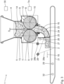
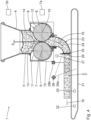
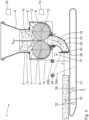
- a device 1 is used to produce a continuous dough band 2 (cf. Fig. 3 and 4 ) and for producing dough portions 3 (cf. Fig. 5 ) in the form of sections of the dough sheet 2.
- the dough sheet portions can be produced in a weight range between, for example, 100 g and 100 kg.
- Typical dough sheet portions have a weight of 200 g, 1 kg, 5 kg, 20 kg, 40 kg or in the range in between. Endless dough strands without division can be processed from the start of production to the end of production.
- the device 1 has a funnel-shaped dough container 4 in sections for holding a dough mass 5.
- the dough mass 5 can be the result of continuous dough production.
- the dough mass 5 can be the result of batch dough production and can have dough portions of different degrees of maturity, in particular kneading portions produced at a time interval. Condition parameters of these dough portions of different degrees of maturity can be recorded by continuous density measurement or batch recognition in order to optimize the dough strand conveyance and can be incorporated into the control of the device 1.
- the dough of the dough mass 5 can be a pastry dough or another food dough, for example a meat dough such as a sausage meat. Another material is also possible.
- the device 1 also has a pair 6 of two dough conveyor rollers 7, 8.
- the two dough conveyor rollers 7, 8 have horizontally extending roller axes 9, 10, which are also referred to as roller rotation axes, and are at the same height in the embodiment shown and are parallel to each other.
- the conveyor rollers 7, 8 have the same conveying distance from one another perpendicular to the roller axes 9, 10 over a predetermined processing axial range. Roller spacings that deviate from parallel spacings, or convex, concave or other spacings are also possible.
- Roller shell walls 11, 12 of the conveyor rollers 7, 8 are spaced apart from one another, so that the two dough conveyor rollers 7, 8 are also horizontally spaced apart from one another.
- An absolute value of a clear distance (conveying distance) A between the adjacent roller shell walls 11, 12 is in the range between 2 mm and 40 mm.
- the distance A specifies a minimum width of a conveying gap between the conveying rollers 7, 8 of the pair 6 along the conveying path 16.
- the specified roller distances are ideal for processing dough. If meat sausage or animal feed is conveyed instead of dough for pastries, larger distances A can also be used. When conveying larger roller gaps or conveyor gaps, the dynamic pressure between the rollers and the outlet nozzle is reduced, which can lead to lower and more variable molding performance.
- the two dough conveyor rollers 7, 8 are oriented in opposite directions, so they rotate in opposite directions during operation of the device 1, as in the Fig. 1 illustrated by arrows 13, 14.
- the two conveyor rollers 7, 8 are about one in the Fig. 1 schematically shown conveyor output 7a driven.
- the two dough conveyor rollers 7, 8 of the pair 6 are arranged in a roller housing 15.
- the roller housing 15 is arranged downstream of the dough container 4 in a conveying path 16 of the dough mass 5.
- FIG. 2 discloses details of a profile design of the roller shell walls 11, 12 of the dough conveyor rollers 7, 8.
- the conveyor ribs 17 i each have the same axial extension along the roller axis 9.
- the conveyor ribs 18 i each have the same axial extension along the roller axis 10.
- the conveying grooves 20 i each have the same axial extent along the roller axis 10.
- An axial extension of one of the conveyor ribs 17i , 18i is in the Fig. 2 designated as B for example.
- An axial extent of the conveying grooves 19i , 20i which is also referred to as the rotational axial distance, is in the Figure 2 denoted by C for example.
- B C.
- An aspect ratio B/C can range between 0.2 and 5.
- roller shell walls 11, 12 of the conveyor rollers 7, 8 of the pair 6 are aligned with one another in such a way that a conveyor rib 17i of one conveyor roller 7 of the pair 6 lies axially at the level of a conveyor groove 19i of the other conveyor roller 8 of the pair 6.
- a conveyor groove 19i of one conveyor roller 7 of the pair 6 lies axially at the level of a conveyor rib 18i of the other conveyor roller 8 of the pair 6.
- a chart insert of the Figure 2 illustrates a rib profile 21 of the roller shell walls 11, 12, i.e. the conveying ribs 17i , 18i on the one hand and the conveying grooves 19i , 20i on the other.
- the rib profile 21 is shown as a profile height y over an axial extension x along the roller axes 9 and 10, respectively.
- the rib profile 21 is continuous and free of edges.
- the rib profile 21 is a sine profile.
- the axial extensions B, C of the conveyor ribs 17i , 18i on the one hand and the conveyor grooves 19i , 20i on the other hand are between the Zero crossings of the rib profile 21 measured.
- the conveyor rib configuration of the dough conveyor rollers 7, 8 leads to an increase in the surface area of the roller shell walls 11, 12 compared to conventional conveyor rollers without such rib profiling.
- This surface area increase can be greater than 10%, can be greater than 25%, can be greater than 50% and can be, for example, 100% or even greater.
- the surface of the respective roller casing wall 11, 12 can therefore be twice as large as the surface of the casing wall of a conventional conveyor roller without rib profiling.
- coarser or finer grooved or ribbed shapes of the conveyor rollers 7, 8 can also be used.
- the roller shell walls 11, 12 of the respective conveyor roller 7, 8 of the pair 6 can have a structuring, which results in a friction-increasing effect between the roller shell walls 11, 12 and the dough mass 5.
- This additional structuring can be achieved by a defined roughening of the roller shell walls 11, 12.
- the distance A between the conveyor rollers 7, 8 of the pair of conveyor rollers 6 can be adjusted using one in the Figure 2 schematically indicated distance adjustment drive 22 can be predetermined.
- the device 1 also has a dough outlet nozzle 23, which is arranged downstream in the roller housing 15 in the conveying path 16 of the dough mass 5, which then has the shape of a dough strand 24.
- the dough outlet nozzle 23 ensures a 90° deflection of the conveying path 16.
- the dough outlet nozzle 23 can also be designed without a deflection or with a deflection angle other than 90°.
- a closure device 26 of the device 1 is arranged in the area of an outlet section 25 of the dough outlet nozzle 23.
- the closure device 26 is designed as a slide, which has a closure drive 27, which is in the Fig. 1 is shown schematically, driven between a closed position (cf. Fig. 1 ) and a release position (cf. Fig. 3 ) can be changed.
- a closed position cf. Fig. 1
- a release position cf. Fig. 3
- the closure device 26 closes the outlet section 25 of the dough outlet nozzle 23.
- the release position the closure device 26 releases the outlet section 25 for the passage of the dough strand 24, which leaves the dough outlet nozzle 23 in the form of the dough strip 2.
- the conveyor rollers 7, 8 of the pair 6 and the dough outlet nozzle 23 are mounted within or on the device 1 in such a way that a quick exchange of the respective component is guaranteed, i.e. a quick exchange between conveyor rollers and / or a quick exchange between dough Exhaust nozzles. It can be exchanged to replace the respective component at the end of its service life or to specify different conveyor path geometries.
- rollers can be used to achieve high adhesion forces between rollers and the media to be conveyed. This makes it possible to convey dough mass, meat mass or alternative viscous masses.
- the choice of materials can include all food-approved materials. Metals, plastics or composite materials are ideal here.
- the surface quality of the rollers can improve or worsen their dragging behavior, depending on the degree of adhesion of the material to be conveyed. Similar effects can be achieved using roller coatings.
- This component set can also include conventional dough conveyor rollers with shell walls without rib profiling.
- the device 1 can be adapted to a composition or a degree of maturity of the dough mass 5. For example, more liquid doughs can be processed with conveyor rollers of larger diameter, i.e. with a smaller distance A.
- An additional structuring or a conveyor rib configuration of the roller casing walls 11, 12 can be selected during the selection so that the conveyor rollers operate as slip-free as possible for the dough of the dough mass 5 to be processed.
- the device 1 also has a volume measuring device 28 for measuring a volume of the dough strip 2 in the conveying path 16 after the dough outlet nozzle 23.
- a measuring device can be used as the volume measuring device 28, which is described in the EP 2 305 039 B1 .
- the volume measuring device 28 is an optical volume measuring device, having a laser light source and at least one, for example two, detector units.
- An optical detection area 28a of the volume measuring device 28 is, for example, in the Figure 1 indicated.
- the device can also have a scale 29 for weighing the dough strip 2 in the conveying path 16 after the dough outlet nozzle 23.
- the device 1 also has a central control device 30, which is in the Fig. 1 is shown schematically.
- the control device 30 is in signal connection with the conveyor drive 7a, the distance adjustment drive 22, the closure drive 27, the volume measuring device 28 and the scales 29 via signal connections (not shown).
- control device 30 a controlled and/or regulated portioning process can be carried out with the device 1.
- the control device 30 may include artificial intelligence (AI).
- the device 1 can be designed overall as a CIP (clean in place) version, so that all dough-contacting components of the device 1 meet strict CIP requirements through appropriate cleaning accessibility. A corresponding accessibility of the components is ensured in the device 1 in particular via a tool-free assembly/disassembly option of the conveyor rollers 7, 8 and the outlet nozzle 23 as well as through easy accessibility of the interior of the dough container 4 and the roller housing 15.
- CIP clean in place
- Fig. 1 shows the situation in which the dough mass 5 filled into the dough container 4 has progressed to such an extent via a conveyance by the pair 6 of the conveyor rollers 7, 8 that the dough outlet nozzle 23 is completely filled up to the closure device 26 in the closed position.
- Fig. 3 shows the situation after the closure device 26 has been changed from the closure position to the release position with the aid of the closure drive 27.
- the dough band 2 then emerges in a defined manner from the dough outlet nozzle 23 and is transported via an endless conveyor belt 31, which represents a delivery conveyor device. transported further along the conveyor path 16.
- the conveyor device 31 is driven via a further conveyor drive 32. This is also in signal connection with the central control device 30.
- the dough strip 2 emerging from the dough outlet nozzle 23 is monitored by sensors via the volume measuring device 28.
- the volume measuring device 28 detects in particular fluctuations of a volume body of the dough band 2 and integrates a volume of the dough band 2 passing through the detection area 28a.
- a further measuring unit 28b (cf. Fig. 1 ) can be provided, which can in particular optically detect whether the dough band is being transported on the endless conveyor belt 31 starting from the closure device 26 or not.
- Fig. 4 shows a current position as the dough band 2 is progressively discharged through the dough outlet nozzle 23.
- the closure device 26 is used to specify a portion of dough in the form of a section of the dough band 2 according to the release position Fig. 3 transferred back into the closed position, so that a portion of dough 3 is pressed off the endless dough belt 2 with the help of the closure device 26.
- the closure device can be controlled depending on a fermentation state of the dough mass, in particular depending on a fermentation state of individual portions, in particular kneading portions of the dough mass 5.
- This information can either be available via data input based on the history of the dough mass 5 or also based on the sensor data from the volume measuring device 28 and/or scale 29.
- Such data can be adapted and optimized via the AI of the control device 30 in a learning process (Machine Learning ML), so that precise dough portioning is the result.
- This component set can also include conventional dough conveyor rollers with shell walls without rib profiling.
- Fig. 5 shows the situation in which the dough band portion 3 was conveyed further along the conveying path 16 with the aid of the conveyor 31 with the closure device 26 closed, so that a corresponding distance F between the nozzle-side end of the dough band portion 3 and the closure device 23 results. Based on the current situation Fig. 5 The closure device 23 can then be switched back to the release position so that the next portion of dough can then be produced. The distance F facilitates further processing of the various dough sheet portions 3.
Landscapes
- Life Sciences & Earth Sciences (AREA)
- Engineering & Computer Science (AREA)
- Food Science & Technology (AREA)
- Manufacturing And Processing Devices For Dough (AREA)
Applications Claiming Priority (1)
| Application Number | Priority Date | Filing Date | Title |
|---|---|---|---|
| DE102022209174.4A DE102022209174A1 (de) | 2022-09-02 | 2022-09-02 | Vorrichtung zur Erzeugung eines kontinuierlichen Teigbandes und von Teigportionen in Form von Abschnitten des Teigbandes |
Publications (1)
| Publication Number | Publication Date |
|---|---|
| EP4331367A1 true EP4331367A1 (fr) | 2024-03-06 |
Family
ID=87889400
Family Applications (1)
| Application Number | Title | Priority Date | Filing Date |
|---|---|---|---|
| EP23194641.9A Pending EP4331367A1 (fr) | 2022-09-02 | 2023-08-31 | Dispositif pour la production d'une bande de pâte continue et de portions de pâte sous forme de sections de la bande de pâte |
Country Status (2)
| Country | Link |
|---|---|
| EP (1) | EP4331367A1 (fr) |
| DE (1) | DE102022209174A1 (fr) |
Citations (13)
| Publication number | Priority date | Publication date | Assignee | Title |
|---|---|---|---|---|
| DE443334C (de) * | 1927-04-27 | Johann Kellnberger | Teigwalzwerk zur Herstellung von Teigstraengen, insbesondere Brezelstraengen | |
| US4375349A (en) * | 1981-12-22 | 1983-03-01 | Branko Vrbanek | Apparatus for shaping dough |
| US5091202A (en) * | 1990-04-17 | 1992-02-25 | Rheon Automatic Machinery Co., Ltd. | Method for manufacturing continuous sheets of bread dough |
| WO1995005742A2 (fr) * | 1993-08-23 | 1995-03-02 | Heat And Control, Inc. | Laminoir ameliore |
| US5419903A (en) * | 1990-12-12 | 1995-05-30 | United Biscuits (Uk) Limited | Product and process of making biscuits with a corrugated configuration |
| EP1602281A1 (fr) * | 2004-05-28 | 2005-12-07 | BARILLA G. e R. Fratelli S.p.A. | Produit de boulangerie cuit à base de pâtisserie contenant de la graisse en forme de grille multi-couches, et appareil et processus de fabrication |
| US7182588B2 (en) * | 2001-12-17 | 2007-02-27 | Koenig Maschinen Gesellschaft M.B.H. | Device for the continuous production of a strip of dough |
| EP1905306A2 (fr) | 2006-09-29 | 2008-04-02 | Werner & Pfleiderer Lebensmitteltechnik GmbH | Dispositif de production et de préparation d'une bande de pâte continue |
| DE102008043090A1 (de) * | 2008-10-22 | 2010-04-29 | Bühler AG | Verfahren und Vorrichtung zur Herstellung von Teig |
| WO2011036683A1 (fr) * | 2009-09-24 | 2011-03-31 | Mario Vincenti | Dispositif pour mouler une pâte alimentaire |
| EP2305039A2 (fr) | 2009-10-01 | 2011-04-06 | Werner & Pfleiderer Industrielle Backtechnik GmbH | Procédé et dispositif de mise en portions d'une multitude de tronçons de pâte dans des portions de pâte individuelles |
| US20200275669A1 (en) * | 2019-02-28 | 2020-09-03 | Ajinomoto Foods North America, Inc. | Method for fabrication of dough sheets and systems, apparatuses, and products thereof |
| US11006636B2 (en) * | 2016-09-16 | 2021-05-18 | Haas Food Equipment Gmbh | Food dough extrusion machine |
-
2022
- 2022-09-02 DE DE102022209174.4A patent/DE102022209174A1/de active Pending
-
2023
- 2023-08-31 EP EP23194641.9A patent/EP4331367A1/fr active Pending
Patent Citations (13)
| Publication number | Priority date | Publication date | Assignee | Title |
|---|---|---|---|---|
| DE443334C (de) * | 1927-04-27 | Johann Kellnberger | Teigwalzwerk zur Herstellung von Teigstraengen, insbesondere Brezelstraengen | |
| US4375349A (en) * | 1981-12-22 | 1983-03-01 | Branko Vrbanek | Apparatus for shaping dough |
| US5091202A (en) * | 1990-04-17 | 1992-02-25 | Rheon Automatic Machinery Co., Ltd. | Method for manufacturing continuous sheets of bread dough |
| US5419903A (en) * | 1990-12-12 | 1995-05-30 | United Biscuits (Uk) Limited | Product and process of making biscuits with a corrugated configuration |
| WO1995005742A2 (fr) * | 1993-08-23 | 1995-03-02 | Heat And Control, Inc. | Laminoir ameliore |
| US7182588B2 (en) * | 2001-12-17 | 2007-02-27 | Koenig Maschinen Gesellschaft M.B.H. | Device for the continuous production of a strip of dough |
| EP1602281A1 (fr) * | 2004-05-28 | 2005-12-07 | BARILLA G. e R. Fratelli S.p.A. | Produit de boulangerie cuit à base de pâtisserie contenant de la graisse en forme de grille multi-couches, et appareil et processus de fabrication |
| EP1905306A2 (fr) | 2006-09-29 | 2008-04-02 | Werner & Pfleiderer Lebensmitteltechnik GmbH | Dispositif de production et de préparation d'une bande de pâte continue |
| DE102008043090A1 (de) * | 2008-10-22 | 2010-04-29 | Bühler AG | Verfahren und Vorrichtung zur Herstellung von Teig |
| WO2011036683A1 (fr) * | 2009-09-24 | 2011-03-31 | Mario Vincenti | Dispositif pour mouler une pâte alimentaire |
| EP2305039A2 (fr) | 2009-10-01 | 2011-04-06 | Werner & Pfleiderer Industrielle Backtechnik GmbH | Procédé et dispositif de mise en portions d'une multitude de tronçons de pâte dans des portions de pâte individuelles |
| US11006636B2 (en) * | 2016-09-16 | 2021-05-18 | Haas Food Equipment Gmbh | Food dough extrusion machine |
| US20200275669A1 (en) * | 2019-02-28 | 2020-09-03 | Ajinomoto Foods North America, Inc. | Method for fabrication of dough sheets and systems, apparatuses, and products thereof |
Also Published As
| Publication number | Publication date |
|---|---|
| DE102022209174A1 (de) | 2024-03-07 |
Similar Documents
| Publication | Publication Date | Title |
|---|---|---|
| DE69031542T2 (de) | Einrichtung zur Messung des Zugwiderstands von Filterzigaretten | |
| EP0652824B1 (fr) | Extrudeuse a vis | |
| DE69106567T2 (de) | Verfahren und Vorrichtung zur Herstellung von Bahnen aus Brotteig. | |
| EP3069834B1 (fr) | Dispositif de séparation d'un tronçon d'une masse alimentaire pâteuse | |
| DE68909588T2 (de) | Kontinuierliche Knetmaschine. | |
| DE69704143T2 (de) | Dosierungsförderschnecke mit mehreren eingeschnittenen Schneckengängen | |
| DE3130676A1 (de) | Vorrichtung zur herstellung von formkoerpern aus plastischem gut | |
| EP3849318B1 (fr) | Dispositif de formation d'une bande de pâte avec dispositif de coupe | |
| EP2510791B1 (fr) | Dispositif de formage d'une bande de pâte à partir de portions de pâtes alimentées | |
| EP1508279B1 (fr) | Procédé et dispositif pour la préparation d'un produit à partir d'une masse de confiserie | |
| EP1543930A2 (fr) | Procédé et dispositif pour le traitement de caoutchouc | |
| EP0226925A2 (fr) | Dispositif pour couper des portions | |
| EP2898783B1 (fr) | Dispositif pour le moulage d'une masse façonnable | |
| DE102005032678A1 (de) | Füllmaschine mit Temperaturüberwachung | |
| EP4331367A1 (fr) | Dispositif pour la production d'une bande de pâte continue et de portions de pâte sous forme de sections de la bande de pâte | |
| EP3081089B1 (fr) | Dispositif et procédé destinés à former des produits alimentaires | |
| EP3346845B1 (fr) | Diviseuse de boulangerie | |
| EP3894203B1 (fr) | Dispositif et procédé pour séparer des substances de fluidités différentes mélangées entre elles | |
| EP3569397B1 (fr) | Dispositif et procédé de séparation les unes des autres des matières mélangées de capacité d'écoulement différente | |
| EP2470004B1 (fr) | Procédé de commande et de surveillance d'un processus de fabrication du beurre automatisé | |
| DE69107118T2 (de) | Vorrichtung zur Abgabe von Teig. | |
| EP0826468B1 (fr) | Dispositif pour couper en cubes de la viande, du saucisson et des produits alimentaires similaires | |
| EP3597387B1 (fr) | Dispositif de mélange des mélanges de caoutchouc doté d'un capteur de surveillance pour tige d'outil mélangeur, utilisation d'un capteur pour surveiller une distance entre une tige d'outil mélangeur et la paroi intérieure d'un boîtier de dispositif ainsi que procédé de surveillance d'une distance entre entre une tige d'outil mélangeur et la paroi intérieure d'un boîtier de dispositif | |
| EP3620054B1 (fr) | Dispositif de production de bande de pâte ainsi que procédé de fonctionnement correspondant | |
| EP2298078A2 (fr) | Dispositif pour le pétrissage de portions de pâte |
Legal Events
| Date | Code | Title | Description |
|---|---|---|---|
| PUAI | Public reference made under article 153(3) epc to a published international application that has entered the european phase |
Free format text: ORIGINAL CODE: 0009012 |
|
| STAA | Information on the status of an ep patent application or granted ep patent |
Free format text: STATUS: THE APPLICATION HAS BEEN PUBLISHED |
|
| AK | Designated contracting states |
Kind code of ref document: A1 Designated state(s): AL AT BE BG CH CY CZ DE DK EE ES FI FR GB GR HR HU IE IS IT LI LT LU LV MC ME MK MT NL NO PL PT RO RS SE SI SK SM TR |
|
| STAA | Information on the status of an ep patent application or granted ep patent |
Free format text: STATUS: REQUEST FOR EXAMINATION WAS MADE |
|
| 17P | Request for examination filed |
Effective date: 20240729 |
|
| RBV | Designated contracting states (corrected) |
Designated state(s): AL AT BE BG CH CY CZ DE DK EE ES FI FR GB GR HR HU IE IS IT LI LT LU LV MC ME MK MT NL NO PL PT RO RS SE SI SK SM TR |
|
| STAA | Information on the status of an ep patent application or granted ep patent |
Free format text: STATUS: EXAMINATION IS IN PROGRESS |
|
| 17Q | First examination report despatched |
Effective date: 20250124 |