EP4331506B1 - Vorrichtung zum abbinden von gewebe - Google Patents
Vorrichtung zum abbinden von gewebe Download PDFInfo
- Publication number
- EP4331506B1 EP4331506B1 EP23194927.2A EP23194927A EP4331506B1 EP 4331506 B1 EP4331506 B1 EP 4331506B1 EP 23194927 A EP23194927 A EP 23194927A EP 4331506 B1 EP4331506 B1 EP 4331506B1
- Authority
- EP
- European Patent Office
- Prior art keywords
- tubular element
- flexible
- arms
- control wire
- target tissue
- Prior art date
- Legal status (The legal status is an assumption and is not a legal conclusion. Google has not performed a legal analysis and makes no representation as to the accuracy of the status listed.)
- Active
Links
Images

Classifications
-
- A—HUMAN NECESSITIES
- A61—MEDICAL OR VETERINARY SCIENCE; HYGIENE
- A61B—DIAGNOSIS; SURGERY; IDENTIFICATION
- A61B17/00—Surgical instruments, devices or methods
- A61B17/12—Surgical instruments, devices or methods for ligaturing or otherwise compressing tubular parts of the body, e.g. blood vessels or umbilical cord
- A61B17/122—Clamps or clips, e.g. for the umbilical cord
-
- A—HUMAN NECESSITIES
- A61—MEDICAL OR VETERINARY SCIENCE; HYGIENE
- A61B—DIAGNOSIS; SURGERY; IDENTIFICATION
- A61B17/00—Surgical instruments, devices or methods
- A61B17/12—Surgical instruments, devices or methods for ligaturing or otherwise compressing tubular parts of the body, e.g. blood vessels or umbilical cord
- A61B17/128—Surgical instruments, devices or methods for ligaturing or otherwise compressing tubular parts of the body, e.g. blood vessels or umbilical cord for applying or removing clamps or clips
- A61B17/1285—Surgical instruments, devices or methods for ligaturing or otherwise compressing tubular parts of the body, e.g. blood vessels or umbilical cord for applying or removing clamps or clips for minimally invasive surgery
-
- A—HUMAN NECESSITIES
- A61—MEDICAL OR VETERINARY SCIENCE; HYGIENE
- A61B—DIAGNOSIS; SURGERY; IDENTIFICATION
- A61B17/00—Surgical instruments, devices or methods
- A61B17/00234—Surgical instruments, devices or methods for minimally invasive surgery
- A61B2017/00292—Surgical instruments, devices or methods for minimally invasive surgery mounted on or guided by flexible, e.g. catheter-like, means
- A61B2017/0034—Surgical instruments, devices or methods for minimally invasive surgery mounted on or guided by flexible, e.g. catheter-like, means adapted to be inserted through a working channel of an endoscope
-
- A—HUMAN NECESSITIES
- A61—MEDICAL OR VETERINARY SCIENCE; HYGIENE
- A61B—DIAGNOSIS; SURGERY; IDENTIFICATION
- A61B17/00—Surgical instruments, devices or methods
- A61B2017/00743—Type of operation; Specification of treatment sites
- A61B2017/00818—Treatment of the gastro-intestinal system
-
- A—HUMAN NECESSITIES
- A61—MEDICAL OR VETERINARY SCIENCE; HYGIENE
- A61B—DIAGNOSIS; SURGERY; IDENTIFICATION
- A61B90/00—Instruments, implements or accessories specially adapted for surgery or diagnosis and not covered by any of the groups A61B1/00 - A61B50/00, e.g. for luxation treatment or for protecting wound edges
- A61B90/03—Automatic limiting or abutting means, e.g. for safety
- A61B2090/037—Automatic limiting or abutting means, e.g. for safety with a frangible part, e.g. by reduced diameter
Definitions
- a device for closing or ligating tissue at the inner wall of a hollow organ such as the digestive tract or other body lumens and hollow organs is provided which is relatively simple to manufacture and use.
- Examples of available devices include tools of the type: " Endoloop ®” or " Polyloop ® ", with difficult positioning due to excessive flexibility of its loop and a complex tightening and separation system.
- the document FR-3 117 327 A relates to an improved device comprising a first and a second arm, a clamping wire connecting the two distal ends of the first and second arms, a flexible control wire passing through a slot, said flexible control wire having at its end a loop surrounding said clamping wire, a projection for retaining the loop and allowing the clamping wire to be fixed in the pulling position and a rigid control wire positioned in a notch.
- the space between the arms is however not clear.
- the present invention therefore aims to remedy these drawbacks: to have a simple tool, which is used in the working channel of an endoscope.
- This device has two rigid arms allowing its easy positioning around the lesion or target tissue area with a predefined clamping force allowing the closure or ligation of the target tissue in an effective and durable manner, it is used by simple introduction into the working channel of the endoscope.
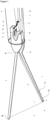
- This device comprises an elongated, flexible tubular element 1, used through a working channel of an endoscope, a proximal end of which remains external to the body, accessible to a user with a joystick (control handle) while a distal end 2 of the flexible element is inserted into the hollow organ after its introduction into the working channel of the endoscope to a location adjacent to the target tissue to be closed or ligated.
- Said device also comprises two control wires, a flexible control wire 9 and a rigid control wire 13 extending through the flexible element 1, the two wires being removably coupled to the device.
- Said device can be made of an insulating material that is not conductive to electrical current (plastic type), for example in the case of resection of ligated tissue with a coagulation section current, or of a conductive material (of electrical current), for example in the case of resection of cold ligated tissue or in the case of use of the device only for closing the tissue.
- plastic type for example in the case of resection of ligated tissue with a coagulation section current
- a conductive material of electrical current
- This device comprises a first 3 and a second 4 arm of a predefined length, the distal end of the second arm 4 is connected by a flexible tightening wire 5 with a predefined length, said flexible tightening wire 5 being able to be made of a predefined resorbable or non-resorbable material.
- the other end of the flexible tightening wire 5 is fixed on the external edge 6 of the distal end of the first arm 3, a loop 7 of said flexible tightening wire 5 passes from the external side into the slot 8 of the distal end of the first arm 3.
- the flexible wire 9 passes through a slot 10 at the proximal portion of the device. Said wire 9 then passes through the loop 7 of the wire 5. Said wire 9 has at its end a loop 11 of predefined size. The loop 11 of the end of the flexible wire 9 is retained on a projection 12 at the proximal end of the device.
- the proximal portion 18 of the device is secured by the distal end 17 of the rigid control wire 13 positioned in a frangible connection 14.
- the curved projection 15 retains the distal end 17 of the rigid control wire 13 in the frangible connection which fails when the device is fully exited from the distal end 2 of the flexible member 1 to separate the device from the tether of the rigid control wire 13.
- An actuator at the proximal end of the flexible member 1 coupled to the rigid control wire 13 and configured to move the device into the end of the flexible member 1 until the first 3 and second 4 arms of the device exit into an open position and its withdrawal into the distal end of the flexible member 1 for a closed configuration.
- the first 3 and second 4 arms of the device have a predefined proximal angulation 16 allowing the two ends of the first 3 and second 4 arms of the device to be separated once they have exited the distal end of the flexible element 1. In the open configuration, the distal ends of the first 3 and second 4 arms of the device are separated, allowing the device to be positioned on the target tissue area to be grasped. In a variant of the embodiments, the first 3 and second 4 arms of the device contain a predefined number of claws oriented towards the internal face allowing the first 3 and second 4 arms to be attached to the target tissue.
- the first 3 arms and second 4 arms of the device are positioned on the target tissue area to be grasped.
- Application of a predefined force to the actuator (control handle) allows the withdrawal of the flexible control wire 9, carrying with it the loop 7 of the flexible clamping wire 5 through the slot 8 in the distal end of the first arm 3 [ Fig 4 ].
- Applying a pulling force at the control handle causes the wire 9 and the loop 7 of the flexible tightening wire 5 to move until it is fixed to the projection 12 at the proximal end of the device, allowing the loop 7 of the flexible tightening wire 5 to be fixed in the pulling position.
- the invention relates in one aspect to a device for closing or ligating tissue at the inner wall of a hollow organ such as the digestive tract or other body lumens and hollow organs characterized in that it comprises a proximal portion, (said proximal portion comprising a slit 10 and a fragile connection 14), a first 3 and a second 4 arm of a predefined length, the distal end of which of the second arm 4 is connected by a flexible tightening wire 5 (of resorbable or non-resorbable material) with a predefined length, a flexible control wire 9 passing through said slit 10, said flexible wire 9 then passes through the loop 7 of the flexible tightening wire 5 (of resorbable or non-resorbable material).
- Said wire 9 has at its end a loop 11 of predefined size.
- the loop 11 of the end of the flexible wire 9 is retained on a projection 12 at the proximal end of the device, said projection 12 allowing to retain the loop 7 and allowing the fixing of the flexible tightening wire 5 in the traction position and a rigid control wire 13 positioned in said fragile connection 14.
- the rigid control wire 13 is configured to move the device in the distal end of a flexible tubular element 1 such that the first 3 and second 4 arms of said device can come out of the flexible tubular element 1 allowing an open position of said device and/or that the first 3 and second 4 arms of said device can be withdrawn into the distal end of the flexible tubular element 1 allowing a closed position of said device.
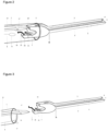
- the proximal portion of the device is secured by the distal end of a rigid control wire 13 positioned in a fragile connection 14 on a curved projection 15 which retains the end of the rigid wire 13 in the fragile connection 14 which fails upon further application of the predefined force of traction on the flexible control wire 9, which allows the loop 11 of the flexible control wire 9 to pass over the projection 15, which causes the distal end of the rigid wire 13 to separate from the fragile connection 14 [ Fig 2 ].
- Applying a pushing force to the control handle of the proximal end of the flexible element 1 causes the device to fully exit the distal end 2 of the flexible tubular element 1 [ Fig 3 ].
- the first 3 and second 4 arms of the device preferably have an angulation 16 [ Fig 1 ] predefined proximal end allowing the separation of the two ends of the first 3 and second 4 arms of the device once exited from the distal end of the flexible tubular element 1 such that in the open position of said device, the distal ends of the first 3 and second 4 arms are separated, allowing said device to be positioned on the target tissue area to be grasped.
- the distal end of the second arm 4 is connected by a flexible tightening wire 5 with a predefined length, said flexible tightening wire 5 of predefined resorbable or non-resorbable material.
- the invention relates in one aspect to a device for closing or ligating tissue at the internal wall of a hollow organ such as the digestive tract or other bodily lumens and hollow organs characterized in that it comprises an elongate and flexible tubular element 1, used through a working channel of an endoscope of which a proximal end remains external to the body, accessible to a user with a joystick while a distal end 2 of the flexible tubular element 1 is inserted into the hollow organ after its introduction into the working channel of the endoscope to a location adjacent to the target tissue to be closed or ligated, said device also comprising two control wires, a flexible control wire 9 and a rigid control wire 13 extending through the flexible tubular element 1, the two control wires 9, 13 being removably coupled to the device, the device comprising a first 3 and a second 4 arm each of a predefined length, the distal end of the second arm 4 being connected by a flexible clamping wire 5 with a predefined length, the other end of the flexible clamping
- the device is therefore preferably designed so that at least part of the flexible control wire 9 extends along the first arm 3, close to the latter and away from the second arm 4. This is notably permitted by the positioning of the slot (more precisely a through-light here) 8, at the level of the first distal end 19 of the first stocking 3, through which the first loop 7 of the tightening wire 5 passes.
- This makes it possible to have a free space, devoid of of wire (in particular flexible control wire 9, or flexible clamping wire 5), as seen in figure 1 , this free space being intended to accommodate the target tissue to be closed or ligated.
- the first loop 7 is therefore advantageously located only in the vicinity of the first distal end 19, because it has not been stretched and therefore has a reduced or minimal size ( figures 1 And 4 ), while in the closed configuration, the first loop 7 advantageously extends all along the first arm 3 up to the proximal part 18 (and more precisely up to the first projection 12), because it has been stretched (by the flexible control wire 9) and therefore has an enlarged or maximum size ( Figures 2 and 3 , and particularly visible at the figure 5 ).
- Said first arm 3 preferably comprising, as illustrated, an inner side or edge 21 facing said second arm 4 as well as an outer side or edge 6 opposite said inner side or edge 21 and therefore facing outwards.
- the first loop 7 therefore passes from the outer side or edge 6 to end up facing the inner side or edge 21, preferably between said first and second arms 3, 4, advantageously in the vicinity of the first distal end 19 of the first arm 3 (at least in the open configuration).
- the device comprises a substantially elongated and flexible tubular element 1, intended to be used through a working channel of an endoscope, a proximal end of which remains external to the body and accessible to a user, for example with a joystick, the tubular element 1 thus comprising a distal end 2 intended to be inserted into the hollow organ after its introduction into the working channel of the endoscope to a location adjacent to the target tissue to be closed or ligated, said flexible control wire 9 extending through said tubular element 1.
- the device preferably comprises a rigid control wire or rod 13 extending through said tubular element 1 to said proximal portion 18, said rigid control wire or rod 13 being adapted to move the proximal portion 18 within the tubular element 1, for example by applying a pushing or pulling force to said rigid control wire or rod 13, the pushing or pulling being preferably carried out relative to the proximal part 18 (pushed towards the proximal part 18, pulled away from it).
- the rigid control wire or rod 18 preferably has its own mechanical strength, and in particular is not flaccid. On the contrary, the flexible control wires 9 and clamping wires 5 are advantageously flaccid, without their own mechanical strength, as illustrated in the figures.
- the transition from the initial configuration to the open configuration is preferably done by applying a pushing force to the rigid control wire or rod 13 within the tubular element 1, said pushing force being transmitted by the rigid control wire or rod 13 to said proximal portion 18.
- the rigid control wire or rod 13 is provided with a fourth distal end 17 designed to interact with said proximal portion 18, and a third proximal end (not illustrated, but preferably located outside the hollow organ) allowing a user to manipulate the movement of said rigid control wire or rod 13 within the tubular element 1, and in particular to push said rigid control wire or rod 13.
- said fourth distal end 17 abuts against the proximal part 18, in particular in the initial configuration and/or in the open configuration.
- the device is advantageously designed so that the application of a pushing force at the third proximal end of the rigid control wire or rod 13 causes the second assembly to completely exit the tubular element 1, as illustrated in figure 3 (more precisely, between the figure 2 and 3 , there is the aforementioned thrust force that has been applied).
- the said second assembly advantageously remains at the location of the ligature or closure of the tissue, while the first assembly is removed from the hollow organ and more generally from the patient's body.
- said proximal portion 18 comprises an elastic return deformation means 16 for automatically positioning the first and second arms 3, 4 at a predefined angulation relative to each other.
- the first and second distal ends 19, 20 are therefore spaced apart from each other, as soon as said first and second arms 3, 4 are extended out of the tubular element. 1 and that the flexible clamping wire 5 is not tensioned or pulled by the flexible control wire 9, in particular in the open configuration, which makes it possible to position said first and second arms 3, 4 at the target tissue to be closed or ligated.
- the elastic return deformation means 16 makes it possible to automatically separate said first and second arms 3, 4, as long as they are not constrained and brought closer to each other by another force, for example exerted by the clamping wire 5 (closed configuration, Figures 2 and 3 ), or by an internal wall of the tubular element 1 (initial configuration, not illustrated here).
- said first loop 7 is positioned substantially between said first and second arms 3, 4.
- said first and second arms 3, 4 form a reclosable clamp, the opening of the clamp being carried out automatically, in the open configuration, using a return means, for example an elastic return deformation means 16, while the closing of the clamp is carried out, in the closed configuration, by the flexible clamping wire 5 which is held in tension to keep said first and second distal ends 19, 20 close to one another.
- a return means for example an elastic return deformation means 16
Landscapes
- Health & Medical Sciences (AREA)
- Surgery (AREA)
- Life Sciences & Earth Sciences (AREA)
- Heart & Thoracic Surgery (AREA)
- Nuclear Medicine, Radiotherapy & Molecular Imaging (AREA)
- Vascular Medicine (AREA)
- Engineering & Computer Science (AREA)
- Biomedical Technology (AREA)
- Reproductive Health (AREA)
- Medical Informatics (AREA)
- Molecular Biology (AREA)
- Animal Behavior & Ethology (AREA)
- General Health & Medical Sciences (AREA)
- Public Health (AREA)
- Veterinary Medicine (AREA)
- Surgical Instruments (AREA)
Claims (11)
- Vorrichtung zum Schließen oder Abbinden eines Zielgewebes an der inneren Wand eines Hohlorgans, wie zum Beispiel des Verdauungstraktes oder anderer Körper- und Organlumen, dadurch gekennzeichnet, dass sie umfasst:• einen proximalen Teil, der mit einem ersten Vorsprung (12) und einem ersten Schlitz (10) versehen ist,• einen ersten Arm (3) und einen zweiten Arm (4), die am proximalen Teil (18) miteinander verbunden sind, wobei der erste Arm (3) mit einem ersten distalen Ende (19) und einem zweiten Schlitz (8) versehen ist und der zweite Arm (4) ein zweites distales Ende (20) aufweist,• einen flexiblen Zugfaden (5), der den ersten und den zweiten Arm (3, 4) an den jeweiligen distalen Enden (19, 20) verbindet und eine erste Schlaufe (7) bildet, die von einer äußeren Seite (6) des ersten Arms (3) in den zweiten Schlitz (8) eintritt,• einen flexiblen Steuerfaden (9) mit einer zweiten Schlaufe (11), wobei die Vorrichtung so ausgelegt ist, dass sie von einer offenen Konfiguration, in der:• das erste und das zweite distale Ende (19, 20) voneinander beabstandet sind,• der Steuerfaden (9) durch den ersten Schlitz (10) zur ersten Schlaufe (7) verläuft, diese durchläuft und dann zum proximalen Teil (18) zurückkehrt, um mit der zweiten Schlaufe (11) am ersten Vorsprung (12) befestigt zu werden, in eine geschlossene Konfiguration übergeht, nachdem eine Zugkraft auf den Steuerfaden (9) ausgeübt wurde, wobei:• der Steuerfaden (9) die erste Schlaufe (7) bis zum ersten Vorsprung (12) zieht, sodass dieser die erste Schlaufe (7) hält,• der Steuerfaden (9) sich vom ersten Vorsprung (12) löst,• das erste und das zweite distale Ende (19, 20) durch den Zugfaden (5) aufeinander zugezogen werden, um das Zielgewebe zu schließen oder abzubinden.
- Vorrichtung zum Schließen oder Abbinden eines Zielgewebes gemäß dem vorangegangenen Anspruch, dadurch gekennzeichnet, dass sie ein im Wesentlichen langgestrecktes und flexibles Rohrelement (1) umfasst, das zur Verwendung durch einen Arbeitskanal eines Endoskops bestimmt ist, dessen proximales Ende außerhalb des Körpers verbleibt und für einen Benutzer zugänglich ist, zum Beispiel mit einem Hebel, wobei das Rohrelement (1) ein drittes distales Ende (2) umfasst, das in das Hohlorgan eingeführt werden soll, nachdem es in den Arbeitskanal des Endoskops eingebracht wurde, zu einer Position neben dem zu schließenden oder abzubindenden Zielgewebe, wobei der Steuerfaden (9) durch das Rohrelement (1) verläuft.
- Vorrichtung zum Schließen oder Abbinden eines Zielgewebes gemäß dem vorangegangenen Anspruch, dadurch gekennzeichnet, dass sie einen starren Steuerdraht oder -stab (13) umfasst, der durch das Rohrelement (1) bis zum proximalen Teil (18) verläuft, wobei der Steuerdraht oder -stab (13) so gestaltet ist, dass er den proximalen Teil (18) innerhalb des Rohrelements (1) bewegt.
- Vorrichtung zum Schließen oder Abbinden eines Zielgewebes gemäß dem vorangegangenen Anspruch, dadurch gekennzeichnet, dass sie so gestaltet ist, dass sie von einer Anfangskonfiguration, in der:• der erste und der zweite Arm (3, 4) im Rohrelement (1) positioniert sind,• die ersten und zweiten distalen Enden (19, 20) durch das umgebende Rohrelement (1) nahe beieinander liegen,• die flexiblen Zug- und Steuerfäden (5, 9) im Wesentlichen wie in der offenen Konfiguration positioniert sind, in die offene Konfiguration übergeht, in der die ersten und zweiten Arme (3, 4) außerhalb des Rohrelements (1) positioniert sind, wobei der Übergang von der Anfangskonfiguration in die offene Konfiguration durch:• das Ausüben einer Schubkraft auf den starren Steuerdraht oder -stab (13) innerhalb des Rohrelements (1) erfolgt, wobei diese Schubkraft durch den Steuerdraht oder - stab (13) auf den proximalen Teil (18) übertragen wird.
- Vorrichtung zum Schließen oder Abbinden eines Zielgewebes gemäß den Ansprüchen 3 oder 4, dadurch gekennzeichnet, dass der starre Steuerdraht oder -stab (13) mit einem vierten distalen Ende (17) versehen ist, das zur Interaktion mit dem proximalen Teil (18) ausgelegt ist, und mit einem dritten proximalen Ende, das es einem Benutzer ermöglicht, den Steuerdraht oder -stab (13) innerhalb des Rohrelements (1) zu bewegen, insbesondere den Steuerdraht oder -stab (13) zu schieben.
- Vorrichtung zum Schließen oder Abbinden eines Zielgewebes gemäß dem vorangegangenen Anspruch, dadurch gekennzeichnet, dass das vierte distale Ende (17) gegen den proximalen Teil (18) anliegt, insbesondere in der Anfangs- und/oder offenen Konfiguration.
- Vorrichtung zum Schließen oder Abbinden eines Zielgewebes gemäß den Ansprüchen 5 oder 6, dadurch gekennzeichnet, dass der Steuerdraht oder -stab (13) an dem vierten distalen Ende (17) ein brüchiges Verbindungsmittel (14) umfasst und der proximale Teil (18) mit einem zweiten Vorsprung (15) versehen ist, vorzugsweise getrennt von dem ersten Vorsprung (12), wobei das brüchige Verbindungsmittel (14) und der zweite Vorsprung (15) so gestaltet sind, dass sie:• in der Anfangs- und/oder offenen Konfiguration miteinander verbunden sind, vorzugsweise mechanisch,• in der geschlossenen Konfiguration voneinander gelöst werden, sodass das Rohrelement (1), der Steuerfaden (9) und der Steuerdraht oder -stab (13) eine erste Einheit bilden, wobei die erste Einheit dann von einer zweiten Einheit getrennt ist, die mindestens den proximalen Teil (18), die ersten und zweiten Arme (3, 4) und den Zugfaden (5) umfasst.
- Vorrichtung zum Schließen oder Abbinden eines Zielgewebes gemäß dem vorangegangenen Anspruch, dadurch gekennzeichnet, dass sie so gestaltet ist, dass durch das Ausüben einer Schubkraft auf das dritte proximale Ende des Steuerdrahts oder -stabs (13) die vollständige Ausbringung der zweiten Einheit aus dem Rohrelement (1) bewirkt wird.
- Vorrichtung gemäß einem der Ansprüche 2 bis 8, dadurch gekennzeichnet, dass der proximale Teil (18) ein elastisches Rückstellmittel (16) umfasst, das dazu dient, die ersten und zweiten Arme (3, 4) in einem voreingestellten Winkel zueinander zu positionieren, wobei die ersten und zweiten distalen Enden (19, 20) voneinander entfernt sind, sobald die ersten und zweiten Arme (3, 4) außerhalb des Rohrelements (1) positioniert sind und der Zugfaden (5) nicht durch den Steuerfaden (9) gespannt oder gezogen wird, insbesondere in der offenen Konfiguration, was es ermöglicht, die ersten und zweiten Arme (3, 4) auf das Zielgewebe auszurichten, das geschlossen oder abgebunden werden soll.
- Vorrichtung gemäß einem der vorangegangenen Ansprüche, dadurch gekennzeichnet, dass die erste Schlaufe (7) im Wesentlichen zwischen den ersten und zweiten Armen (3, 4) positioniert ist.
- Vorrichtung gemäß einem der vorangegangenen Ansprüche, dadurch gekennzeichnet, dass die ersten und zweiten Arme (3, 4) eine schließbare Zange bilden, wobei die Öffnung der Zange in der offenen Konfiguration automatisch durch ein Rückstellmittel, beispielsweise ein elastisches Rückstellverformungsmittel (16), erfolgt, während das Schließen der Zange in der geschlossenen Konfiguration durch den Zugfaden (5) erfolgt, der gespannt bleibt, um die ersten und zweiten distalen Enden (19, 20) nahe beieinander zu halten.
Applications Claiming Priority (1)
| Application Number | Priority Date | Filing Date | Title |
|---|---|---|---|
| FR2208854A FR3139271B1 (fr) | 2022-09-03 | 2022-09-03 | Dispositif pour ligature de tissu. |
Publications (2)
| Publication Number | Publication Date |
|---|---|
| EP4331506A1 EP4331506A1 (de) | 2024-03-06 |
| EP4331506B1 true EP4331506B1 (de) | 2025-01-22 |
Family
ID=86468762
Family Applications (1)
| Application Number | Title | Priority Date | Filing Date |
|---|---|---|---|
| EP23194927.2A Active EP4331506B1 (de) | 2022-09-03 | 2023-09-01 | Vorrichtung zum abbinden von gewebe |
Country Status (2)
| Country | Link |
|---|---|
| EP (1) | EP4331506B1 (de) |
| FR (1) | FR3139271B1 (de) |
Family Cites Families (3)
| Publication number | Priority date | Publication date | Assignee | Title |
|---|---|---|---|---|
| US8764774B2 (en) * | 2010-11-09 | 2014-07-01 | Cook Medical Technologies Llc | Clip system having tether segments for closure |
| CA3070720A1 (en) * | 2017-10-11 | 2019-04-18 | Boston Scientific Scimed, Inc. | Reinforced mechanical hemostasis clip |
| FR3117327B1 (fr) * | 2020-12-13 | 2022-10-28 | Abdelkrim Kada | Dispositif pour l’hémostase ou la fermeture de tissu. |
-
2022
- 2022-09-03 FR FR2208854A patent/FR3139271B1/fr active Active
-
2023
- 2023-09-01 EP EP23194927.2A patent/EP4331506B1/de active Active
Also Published As
| Publication number | Publication date |
|---|---|
| FR3139271A1 (fr) | 2024-03-08 |
| FR3139271B1 (fr) | 2024-07-26 |
| EP4331506A1 (de) | 2024-03-06 |
Similar Documents
| Publication | Publication Date | Title |
|---|---|---|
| JP7794869B2 (ja) | 外部器具チャネルを有する内視鏡縫合システム | |
| EP2327364B1 (de) | Ligaturvorrichtung | |
| EP2345377B1 (de) | Vorrichtung zum abbinden anatomischer Strukturen | |
| EP1882451B1 (de) | Clipvorrichtung zum Abbinden von lebendem Gewebe | |
| EP0369324B1 (de) | Chirurgisches Instrument | |
| JP2022539372A (ja) | クランプ装置及びその挟持部 | |
| FR2640131A1 (fr) | Ensemble a ligaturer pour chirurgie endoscopique, ligature et instrument de manipulation de ligature pour cet ensemble | |
| US8603111B2 (en) | Ligating apparatus | |
| EP3905970B1 (de) | System mit kurzer hämostatischer klammer | |
| EP4331506B1 (de) | Vorrichtung zum abbinden von gewebe | |
| JPH05212043A (ja) | クリップ装置 | |
| US20030216752A1 (en) | Device for laparoscopic tubal ligation | |
| WO2022072041A1 (en) | Repositionable closure device | |
| FR2698778A1 (fr) | Spéculum. | |
| US20110270234A1 (en) | Endoscopic surgical instrument | |
| FR3117327A1 (fr) | Dispositif pour l’hémostase ou la fermeture de tissu. | |
| FR2831791A1 (fr) | Dispositif pour l'introduction et la mise en place d'un lacs notamment en chirurgie endoscopique | |
| JP2005224392A (ja) | 内視鏡用把持鉗子 | |
| WO2003103503A1 (fr) | Pince a biopsie endoscopique a instrument de coupe protege |
Legal Events
| Date | Code | Title | Description |
|---|---|---|---|
| PUAI | Public reference made under article 153(3) epc to a published international application that has entered the european phase |
Free format text: ORIGINAL CODE: 0009012 |
|
| STAA | Information on the status of an ep patent application or granted ep patent |
Free format text: STATUS: THE APPLICATION HAS BEEN PUBLISHED |
|
| AK | Designated contracting states |
Kind code of ref document: A1 Designated state(s): AL AT BE BG CH CY CZ DE DK EE ES FI FR GB GR HR HU IE IS IT LI LT LU LV MC ME MK MT NL NO PL PT RO RS SE SI SK SM TR |
|
| STAA | Information on the status of an ep patent application or granted ep patent |
Free format text: STATUS: REQUEST FOR EXAMINATION WAS MADE |
|
| 17P | Request for examination filed |
Effective date: 20240719 |
|
| RBV | Designated contracting states (corrected) |
Designated state(s): AL AT BE BG CH CY CZ DE DK EE ES FI FR GB GR HR HU IE IS IT LI LT LU LV MC ME MK MT NL NO PL PT RO RS SE SI SK SM TR |
|
| GRAP | Despatch of communication of intention to grant a patent |
Free format text: ORIGINAL CODE: EPIDOSNIGR1 |
|
| STAA | Information on the status of an ep patent application or granted ep patent |
Free format text: STATUS: GRANT OF PATENT IS INTENDED |
|
| GRAS | Grant fee paid |
Free format text: ORIGINAL CODE: EPIDOSNIGR3 |
|
| RIC1 | Information provided on ipc code assigned before grant |
Ipc: A61B 90/00 20160101ALN20240906BHEP Ipc: A61B 17/00 20060101ALN20240906BHEP Ipc: A61B 17/128 20060101ALI20240906BHEP Ipc: A61B 17/122 20060101AFI20240906BHEP |
|
| INTG | Intention to grant announced |
Effective date: 20240920 |
|
| GRAA | (expected) grant |
Free format text: ORIGINAL CODE: 0009210 |
|
| STAA | Information on the status of an ep patent application or granted ep patent |
Free format text: STATUS: THE PATENT HAS BEEN GRANTED |
|
| AK | Designated contracting states |
Kind code of ref document: B1 Designated state(s): AL AT BE BG CH CY CZ DE DK EE ES FI FR GB GR HR HU IE IS IT LI LT LU LV MC ME MK MT NL NO PL PT RO RS SE SI SK SM TR |
|
| REG | Reference to a national code |
Ref country code: GB Ref legal event code: FG4D Free format text: NOT ENGLISH |
|
| REG | Reference to a national code |
Ref country code: CH Ref legal event code: EP |
|
| REG | Reference to a national code |
Ref country code: IE Ref legal event code: FG4D Free format text: LANGUAGE OF EP DOCUMENT: FRENCH |
|
| REG | Reference to a national code |
Ref country code: DE Ref legal event code: R096 Ref document number: 602023001761 Country of ref document: DE |
|
| REG | Reference to a national code |
Ref country code: NL Ref legal event code: MP Effective date: 20250122 |
|
| PG25 | Lapsed in a contracting state [announced via postgrant information from national office to epo] |
Ref country code: NL Free format text: LAPSE BECAUSE OF FAILURE TO SUBMIT A TRANSLATION OF THE DESCRIPTION OR TO PAY THE FEE WITHIN THE PRESCRIBED TIME-LIMIT Effective date: 20250122 |
|
| PG25 | Lapsed in a contracting state [announced via postgrant information from national office to epo] |
Ref country code: RS Free format text: LAPSE BECAUSE OF FAILURE TO SUBMIT A TRANSLATION OF THE DESCRIPTION OR TO PAY THE FEE WITHIN THE PRESCRIBED TIME-LIMIT Effective date: 20250422 |
|
| PG25 | Lapsed in a contracting state [announced via postgrant information from national office to epo] |
Ref country code: FI Free format text: LAPSE BECAUSE OF FAILURE TO SUBMIT A TRANSLATION OF THE DESCRIPTION OR TO PAY THE FEE WITHIN THE PRESCRIBED TIME-LIMIT Effective date: 20250122 |
|
| PG25 | Lapsed in a contracting state [announced via postgrant information from national office to epo] |
Ref country code: PL Free format text: LAPSE BECAUSE OF FAILURE TO SUBMIT A TRANSLATION OF THE DESCRIPTION OR TO PAY THE FEE WITHIN THE PRESCRIBED TIME-LIMIT Effective date: 20250122 |
|
| PG25 | Lapsed in a contracting state [announced via postgrant information from national office to epo] |
Ref country code: ES Free format text: LAPSE BECAUSE OF FAILURE TO SUBMIT A TRANSLATION OF THE DESCRIPTION OR TO PAY THE FEE WITHIN THE PRESCRIBED TIME-LIMIT Effective date: 20250122 |
|
| REG | Reference to a national code |
Ref country code: LT Ref legal event code: MG9D |
|
| PG25 | Lapsed in a contracting state [announced via postgrant information from national office to epo] |
Ref country code: NO Free format text: LAPSE BECAUSE OF FAILURE TO SUBMIT A TRANSLATION OF THE DESCRIPTION OR TO PAY THE FEE WITHIN THE PRESCRIBED TIME-LIMIT Effective date: 20250422 Ref country code: IS Free format text: LAPSE BECAUSE OF FAILURE TO SUBMIT A TRANSLATION OF THE DESCRIPTION OR TO PAY THE FEE WITHIN THE PRESCRIBED TIME-LIMIT Effective date: 20250522 |
|
| REG | Reference to a national code |
Ref country code: AT Ref legal event code: MK05 Ref document number: 1760850 Country of ref document: AT Kind code of ref document: T Effective date: 20250122 |
|
| PG25 | Lapsed in a contracting state [announced via postgrant information from national office to epo] |
Ref country code: HR Free format text: LAPSE BECAUSE OF FAILURE TO SUBMIT A TRANSLATION OF THE DESCRIPTION OR TO PAY THE FEE WITHIN THE PRESCRIBED TIME-LIMIT Effective date: 20250122 |
|
| PG25 | Lapsed in a contracting state [announced via postgrant information from national office to epo] |
Ref country code: LV Free format text: LAPSE BECAUSE OF FAILURE TO SUBMIT A TRANSLATION OF THE DESCRIPTION OR TO PAY THE FEE WITHIN THE PRESCRIBED TIME-LIMIT Effective date: 20250122 Ref country code: PT Free format text: LAPSE BECAUSE OF FAILURE TO SUBMIT A TRANSLATION OF THE DESCRIPTION OR TO PAY THE FEE WITHIN THE PRESCRIBED TIME-LIMIT Effective date: 20250522 |
|
| PG25 | Lapsed in a contracting state [announced via postgrant information from national office to epo] |
Ref country code: BG Free format text: LAPSE BECAUSE OF FAILURE TO SUBMIT A TRANSLATION OF THE DESCRIPTION OR TO PAY THE FEE WITHIN THE PRESCRIBED TIME-LIMIT Effective date: 20250122 Ref country code: GR Free format text: LAPSE BECAUSE OF FAILURE TO SUBMIT A TRANSLATION OF THE DESCRIPTION OR TO PAY THE FEE WITHIN THE PRESCRIBED TIME-LIMIT Effective date: 20250423 |
|
| PG25 | Lapsed in a contracting state [announced via postgrant information from national office to epo] |
Ref country code: AT Free format text: LAPSE BECAUSE OF FAILURE TO SUBMIT A TRANSLATION OF THE DESCRIPTION OR TO PAY THE FEE WITHIN THE PRESCRIBED TIME-LIMIT Effective date: 20250122 |
|
| PG25 | Lapsed in a contracting state [announced via postgrant information from national office to epo] |
Ref country code: SE Free format text: LAPSE BECAUSE OF FAILURE TO SUBMIT A TRANSLATION OF THE DESCRIPTION OR TO PAY THE FEE WITHIN THE PRESCRIBED TIME-LIMIT Effective date: 20250122 |
|
| PG25 | Lapsed in a contracting state [announced via postgrant information from national office to epo] |
Ref country code: SM Free format text: LAPSE BECAUSE OF FAILURE TO SUBMIT A TRANSLATION OF THE DESCRIPTION OR TO PAY THE FEE WITHIN THE PRESCRIBED TIME-LIMIT Effective date: 20250122 |
|
| PG25 | Lapsed in a contracting state [announced via postgrant information from national office to epo] |
Ref country code: DK Free format text: LAPSE BECAUSE OF FAILURE TO SUBMIT A TRANSLATION OF THE DESCRIPTION OR TO PAY THE FEE WITHIN THE PRESCRIBED TIME-LIMIT Effective date: 20250122 |
|
| PGFP | Annual fee paid to national office [announced via postgrant information from national office to epo] |
Ref country code: DE Payment date: 20250602 Year of fee payment: 5 |
|
| PG25 | Lapsed in a contracting state [announced via postgrant information from national office to epo] |
Ref country code: IT Free format text: LAPSE BECAUSE OF FAILURE TO SUBMIT A TRANSLATION OF THE DESCRIPTION OR TO PAY THE FEE WITHIN THE PRESCRIBED TIME-LIMIT Effective date: 20250122 |
|
| PG25 | Lapsed in a contracting state [announced via postgrant information from national office to epo] |
Ref country code: EE Free format text: LAPSE BECAUSE OF FAILURE TO SUBMIT A TRANSLATION OF THE DESCRIPTION OR TO PAY THE FEE WITHIN THE PRESCRIBED TIME-LIMIT Effective date: 20250122 Ref country code: CZ Free format text: LAPSE BECAUSE OF FAILURE TO SUBMIT A TRANSLATION OF THE DESCRIPTION OR TO PAY THE FEE WITHIN THE PRESCRIBED TIME-LIMIT Effective date: 20250122 |
|
| REG | Reference to a national code |
Ref country code: DE Ref legal event code: R097 Ref document number: 602023001761 Country of ref document: DE |
|
| PG25 | Lapsed in a contracting state [announced via postgrant information from national office to epo] |
Ref country code: RO Free format text: LAPSE BECAUSE OF FAILURE TO SUBMIT A TRANSLATION OF THE DESCRIPTION OR TO PAY THE FEE WITHIN THE PRESCRIBED TIME-LIMIT Effective date: 20250122 |
|
| PG25 | Lapsed in a contracting state [announced via postgrant information from national office to epo] |
Ref country code: SK Free format text: LAPSE BECAUSE OF FAILURE TO SUBMIT A TRANSLATION OF THE DESCRIPTION OR TO PAY THE FEE WITHIN THE PRESCRIBED TIME-LIMIT Effective date: 20250122 |
|
| PLBE | No opposition filed within time limit |
Free format text: ORIGINAL CODE: 0009261 |
|
| STAA | Information on the status of an ep patent application or granted ep patent |
Free format text: STATUS: NO OPPOSITION FILED WITHIN TIME LIMIT |
|
| 26N | No opposition filed |
Effective date: 20251023 |
|
| PGFP | Annual fee paid to national office [announced via postgrant information from national office to epo] |
Ref country code: IE Payment date: 20251130 Year of fee payment: 3 |