EP4331732A1 - Behälter - Google Patents
Behälter Download PDFInfo
- Publication number
- EP4331732A1 EP4331732A1 EP22795529.1A EP22795529A EP4331732A1 EP 4331732 A1 EP4331732 A1 EP 4331732A1 EP 22795529 A EP22795529 A EP 22795529A EP 4331732 A1 EP4331732 A1 EP 4331732A1
- Authority
- EP
- European Patent Office
- Prior art keywords
- container
- storage space
- main body
- forming unit
- space forming
- Prior art date
- Legal status (The legal status is an assumption and is not a legal conclusion. Google has not performed a legal analysis and makes no representation as to the accuracy of the status listed.)
- Pending
Links
Images




Classifications
-
- B—PERFORMING OPERATIONS; TRANSPORTING
- B05—SPRAYING OR ATOMISING IN GENERAL; APPLYING FLUENT MATERIALS TO SURFACES, IN GENERAL
- B05C—APPARATUS FOR APPLYING FLUENT MATERIALS TO SURFACES, IN GENERAL
- B05C5/00—Apparatus in which liquid or other fluent material is projected, poured or allowed to flow on to the surface of the work
- B05C5/02—Apparatus in which liquid or other fluent material is projected, poured or allowed to flow on to the surface of the work the liquid or other fluent material being discharged through an outlet orifice by pressure, e.g. from an outlet device in contact or almost in contact, with the work
-
- G—PHYSICS
- G03—PHOTOGRAPHY; CINEMATOGRAPHY; ANALOGOUS TECHNIQUES USING WAVES OTHER THAN OPTICAL WAVES; ELECTROGRAPHY; HOLOGRAPHY
- G03F—PHOTOMECHANICAL PRODUCTION OF TEXTURED OR PATTERNED SURFACES, e.g. FOR PRINTING, FOR PROCESSING OF SEMICONDUCTOR DEVICES; MATERIALS THEREFOR; ORIGINALS THEREFOR; APPARATUS SPECIALLY ADAPTED THEREFOR
- G03F7/00—Photomechanical, e.g. photolithographic, production of textured or patterned surfaces, e.g. printing surfaces; Materials therefor, e.g. comprising photoresists; Apparatus specially adapted therefor
- G03F7/16—Coating processes; Apparatus therefor
- G03F7/162—Coating on a rotating support, e.g. using a whirler or a spinner
-
- H—ELECTRICITY
- H10—SEMICONDUCTOR DEVICES; ELECTRIC SOLID-STATE DEVICES NOT OTHERWISE PROVIDED FOR
- H10P—GENERIC PROCESSES OR APPARATUS FOR THE MANUFACTURE OR TREATMENT OF DEVICES COVERED BY CLASS H10
- H10P72/00—Handling or holding of wafers, substrates or devices during manufacture or treatment thereof
- H10P72/04—Apparatus for manufacture or treatment
- H10P72/0448—Apparatus for applying a liquid, a resin, an ink or the like
-
- B—PERFORMING OPERATIONS; TRANSPORTING
- B05—SPRAYING OR ATOMISING IN GENERAL; APPLYING FLUENT MATERIALS TO SURFACES, IN GENERAL
- B05C—APPARATUS FOR APPLYING FLUENT MATERIALS TO SURFACES, IN GENERAL
- B05C11/00—Component parts, details or accessories not specifically provided for in groups B05C1/00 - B05C9/00
- B05C11/02—Apparatus for spreading or distributing liquids or other fluent materials already applied to a surface ; Controlling means therefor; Control of the thickness of a coating by spreading or distributing liquids or other fluent materials already applied to the coated surface
- B05C11/08—Spreading liquid or other fluent material by manipulating the work, e.g. tilting
-
- B—PERFORMING OPERATIONS; TRANSPORTING
- B05—SPRAYING OR ATOMISING IN GENERAL; APPLYING FLUENT MATERIALS TO SURFACES, IN GENERAL
- B05C—APPARATUS FOR APPLYING FLUENT MATERIALS TO SURFACES, IN GENERAL
- B05C11/00—Component parts, details or accessories not specifically provided for in groups B05C1/00 - B05C9/00
- B05C11/10—Storage, supply or control of liquid or other fluent material; Recovery of excess liquid or other fluent material
-
- B—PERFORMING OPERATIONS; TRANSPORTING
- B05—SPRAYING OR ATOMISING IN GENERAL; APPLYING FLUENT MATERIALS TO SURFACES, IN GENERAL
- B05C—APPARATUS FOR APPLYING FLUENT MATERIALS TO SURFACES, IN GENERAL
- B05C5/00—Apparatus in which liquid or other fluent material is projected, poured or allowed to flow on to the surface of the work
- B05C5/02—Apparatus in which liquid or other fluent material is projected, poured or allowed to flow on to the surface of the work the liquid or other fluent material being discharged through an outlet orifice by pressure, e.g. from an outlet device in contact or almost in contact, with the work
- B05C5/0208—Apparatus in which liquid or other fluent material is projected, poured or allowed to flow on to the surface of the work the liquid or other fluent material being discharged through an outlet orifice by pressure, e.g. from an outlet device in contact or almost in contact, with the work for applying liquid or other fluent material to separate articles
-
- H—ELECTRICITY
- H10—SEMICONDUCTOR DEVICES; ELECTRIC SOLID-STATE DEVICES NOT OTHERWISE PROVIDED FOR
- H10P—GENERIC PROCESSES OR APPARATUS FOR THE MANUFACTURE OR TREATMENT OF DEVICES COVERED BY CLASS H10
- H10P52/00—Grinding, lapping or polishing of wafers, substrates or parts of devices
-
- H—ELECTRICITY
- H10—SEMICONDUCTOR DEVICES; ELECTRIC SOLID-STATE DEVICES NOT OTHERWISE PROVIDED FOR
- H10P—GENERIC PROCESSES OR APPARATUS FOR THE MANUFACTURE OR TREATMENT OF DEVICES COVERED BY CLASS H10
- H10P72/00—Handling or holding of wafers, substrates or devices during manufacture or treatment thereof
- H10P72/30—Handling or holding of wafers, substrates or devices during manufacture or treatment thereof for conveying, e.g. between different workstations
-
- H—ELECTRICITY
- H10—SEMICONDUCTOR DEVICES; ELECTRIC SOLID-STATE DEVICES NOT OTHERWISE PROVIDED FOR
- H10P—GENERIC PROCESSES OR APPARATUS FOR THE MANUFACTURE OR TREATMENT OF DEVICES COVERED BY CLASS H10
- H10P76/00—Manufacture or treatment of masks on semiconductor bodies, e.g. by lithography or photolithography
Definitions
- Patent Document 1 describes a substrate processing apparatus (coating apparatus) that supplies resist (a photoresist liquid) as a processing liquid to a substrate to form a resist film by spin coating.
- This coating apparatus is equipped with a storage tank storing the resist therein; a supply nozzle; and a supply pipe connecting the storage tank and the supply nozzle and provided with a bellows pump.
- Patent Document 1 Japanese Patent Laid-open Publication No. H11-354419
- Exemplary embodiments provide a technique capable of reducing, when processing a substrate by using a processing liquid, a burden in the processing and a burden in works involved in the processing.
- a container in an exemplary embodiment, includes a storage space forming unit in which a storage space storing therein a processing liquid configured to process a substrate is formed; a discharge port of the processing liquid, provided in the storage space forming unit; and a fragile member provided in the storage space forming unit and configured to be broken by being pressurized with a penetrating member in order to form an access path, the penetrating member being configured to pressurize the storage space such that the processing liquid is discharged from the discharge port, and the penetrating member being advanced into the storage space forming unit through the access path.
- a resist coating apparatus 1 including a container according to an exemplary embodiment of the present disclosure will be described with reference to a plan view of FIG. 1 and a schematic side view of FIG. 2 .
- the resist coating apparatus 1 is configured to supply resist as a processing liquid to a wafer W, which is a circular substrate, and forms a resist film by spin coating.
- This resist coating apparatus 1 is equipped with a cup 11, a container 2, a transfer unit 6, a container placement unit 8, and a base 19.
- a plurality of, for example, two containers 2 are disposed in the container placement unit 8, and different types of resist are stored in these containers 2, for example.
- a container nozzle 20 constituting the container 2 is used not only as a nozzle but also as a tank configured to store the resist therein.
- the transfer unit 6 is configured to mount and grip the container nozzle 20 of selected one of the containers 2 and transfer it from the container placement unit 8 to a processing position above the wafer W within the cup 11, and then, is configured to discharge the resist onto the wafer W from the container nozzle 20.
- the container nozzle 20 before being mounted to the transfer unit 6 is configured to have a hermetically sealed inside.
- a fragile member 47 forming a wall portion of the container nozzle 20 is broken and deformed by being pressurized by a supply/exhaust pipe 68 that constitutes the transfer unit 6.
- the supply/exhaust pipe 68 is put into the container nozzle 20 through an access path 47A formed as a result of the breaking and deformation of the fragile member 47.
- the container nozzle 20 By supplying a gas and exhausting the gas from the supply/exhaust pipe 68, the container nozzle 20 can be pressurized and decompressed, and the discharge and the stop of the discharge of the resist are switched. The container nozzle 20 after being used is released from the transfer unit 6, and is then returned back to the container placement unit 8.
- the cup 11 and the container placement unit 8 are disposed on the right side and the left side of the base 19, respectively.
- a spin chuck 12 is provided in the cup 11.
- the spin chuck 12 is configured to attract a central portion of a rear surface of the wafer W and hold the wafer W horizontally.
- the spin chuck 12 is connected to a rotation mechanism 13, and the wafer W is rotated around a vertical axis along with the spin chuck 12 by the rotation mechanism 13.
- the wafer W is transferred to above the cup 11 from a transfer area behind the cup 11 by a non-illustrated transfer mechanism.
- the wafer W is handed over between the transfer mechanism above the cup 11 and the spin chuck 12 by a non-illustrated elevating pin provided in the cup 11.
- the containers 2 are arranged in a layout that allows the container nozzle 20 to be mounted to and gripped by the transfer unit 6, which will be described in detail later.
- the container placement unit 8 is provided with two recessed portions 81 arranged in a left-and-right direction, and the containers 2 are respectively disposed in these recessed portions 81.
- a lower cover 31 constituting the container 2 is fixed to the recessed portion 81, and attachment/detachment of this lower cover 31 to/from the container nozzle 20 is enabled by an elevating operation of the transfer unit 6 gripping the container nozzle 20. This attachment/detachment of the lower cover 31 will be described in detail later.
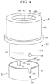
- the container 2 has a vertically elongated cylindrical shape, and is composed of a container main body 21, the lower cover 31, an upper cover 41, and an inner cover 51.
- the container nozzle 20 is composed of the container main body 21, the upper cover 41, and the inner cover 51, and its outer surface is formed by the container main body 21 and the upper cover 41. That is, the inner cover 51 is provided in a space formed by the container main body 21 and the upper cover 41. Further, the container nozzle 20 is a storage space forming unit having a storage space 59 therein.
- FIG. 3 illustrates a state in which the lower cover 31 is attached
- FIG. 4 illustrates a state in which the lower cover 31 is separated.
- the lower cover 31 is fixed to the container placement unit 8, and the lower cover 31 is detached when the container nozzle 20 is transferred by the transfer unit 6 as described above.
- the container main body 21, the lower cover 31, the upper cover 41, and the inner cover 51 that constitute the container 2 are circular members whose central axes are coincident when viewed from the top.
- the container main body 21, the lower cover 31, and the upper cover 41 are made of, for example, an integrally molded resin. Specifically, they are made of a thermoplastic resin, desirably, polyolefin, and, more desirably, polyethylene or polypropylene.
- the container main body 21 includes a cylindrical member 22 forming a body thereof, and this cylindrical member 22 forms the storage space 59 for resist.
- a portion of the container main body 21 under the cylindrical member 22 is formed in a funnel shape.
- a lower peripheral wall of the cylindrical member 22 is elongated toward the central axis of the container main body 21 as it goes downwards, forming an inclined wall 23.
- a lower end of this inclined wall 23 is slightly extended vertically downwards to form a leading end portion 24.
- An area surrounded by this leading end portion 24 is configured as a discharge port 25 opened downwards, and the center of this discharge port 25 lies on the central axis of the container main body 21.
- the resist in the container main body 21 flows down toward the discharge port 25 along an inner peripheral surface 23A of the inclined wall 23 when using up the resist in the storage space 59, so that the liquid is suppressed from remaining in the container main body 21.
- the angle formed by the inner peripheral surface 23A of the inclined wall 23 and a horizontal plane is set to ⁇ 1. If the angle ⁇ 1 is too small, it becomes difficult for the resist to flow down, whereas if the angle ⁇ 1 is too large, the height of the bottom of the container main body 21 increases. Therefore, the angle ⁇ 1 is desirably set to be in the range of 1° to 60°, and, more desirably, in the range of 1° to 45°.
- the resist may leak out, whereas if the hole diameter L1 is too small, it may be difficult to fill the inside of the leading end portion 24 with the resist by the pressure of the storage space 59. On this ground, it is desirable to set the hole diameter L1 to 0.5 mm to 2.0 mm.
- L0 denotes the length of the discharge port 25. If this length L0 is too large, it becomes difficult for the resist to flow down. If the length L0 is too small, on the other hand, the resist may flow too easily. Thus, it is desirable to set the length L0 to, e.g., 4 mm or more. In addition, it is desirable to design the hole diameter L1 and the length L0 of the discharge port 25 to have optimal sizes in consideration of the size of the container 2, the viscosity of the resist, etc.
- a central portion of an outer peripheral surface of the cylindrical member 22 in a height direction is protruded toward the outside of the cylindrical member 22, thereby forming an annular handle 26. Accordingly, this handle 26 is a protruding portion that is projected toward the outside of the container main body 21 on the lateral side of the container main body 21 along the circumferential direction of the container main body 21. Furter, the upper cover 41 is provided above the handle 26. As described above, since the individual members constituting the container 2 are integrally molded, the handle 26 is formed integrally with the cylindrical member 22, and, therefore, cannot be detached from the cylindrical member 22. As will be described later, the transfer unit 6 grips the handle 26.
- a spiral protrusion is formed along the outer peripheral surface of the cylindrical member 22 with the central axis of the cylindrical member 22 as a spiral axis, forming a male screw 27.
- two protrusions 28 protruding in the horizontal direction are formed on the outer peripheral surface of the cylindrical member 22 below the handle 26. These protrusions 28 are formed as portions of the outer peripheral surface of the cylindrical member 22, which are spaced apart from each other at an angular interval of 180° with respect to the central axis of the cylindrical member 22 and have the same height, are protruded in opposite directions.
- Each protrusion 28 has a circular shape, when viewed from the protruding direction.
- the lower cover 31 is composed of a vertically standing cylindrical member 32 and a bottom plate 33 that closes a lower portion of the cylindrical member 32.
- the cylindrical member 32 surrounds a lower portion of the container main body 21.
- the groove 35 is formed in a keyhole shape.
- a width of an upper portion of the groove 35 becomes slightly narrower as it goes downwards, and a width at a lower end thereof is slightly smaller than the diameter of the circle when the protrusions 28 is viewed from the protruding direction.
- a lower portion of the groove 35 is formed in a circular shape, and its size is approximately equal to the size of the circle when the protrusion 28 is viewed from the protruding direction. Therefore, it can be said that a constriction portion that narrows the width of the groove 35 is provided on the way the groove 35 goes downwards.
- the mount of the lower cover 31 to the container main body 21 will be described.
- the container main body 21 is moved relative to the lower cover 31 along the axial direction to come closer to the lower cover 31, thus allowing the protrusions 28 to be put into the grooves 35.
- the protrusion 28 is moved to the inside of the groove 35 beyond the constriction portion of the groove 35, and the protrusion 28 and the groove 35 are engaged with each other (joined together).
- the protrusion 28 and the groove 35 are configured as an engaging member and an engaged member, respectively, and they form an engagement between the container main body 21 and the lower cover 31 to fix their relative positions.
- the lower cover 31 since the lower portion of the container main body 21 has a pointed shape due to the presence of the inclined wall 23, the lower cover 31 also has, in addition to the above-described function of blocking the discharge port 25, a function of suppressing, when mounted to the container main body 21, the container main body 21 from being tilted, thus enabling the container main body 21 to maintain a proper posture.
- the protrusion 28 is moved beyond the constriction portion to an inlet of the groove 35, and the engagement is released.
- the lower cover 31 is separated from the container main body 21.
- the lower cover 31 is fixed to the container placement unit 8, and in that state, the transfer unit 6 holding the container nozzle 20 including the container main body 21 is moved up and down with respect to the lower cover 31. As a result, such engagement and release of the engagement are performed.
- a through hole 36 is formed at the cylindrical member 32 of the lower cover 31 to be positioned under one of the grooves 35, and this through hole 36 is opened to a space surrounded by the inclined wall 23 of the container main body 21 and the lower cover 31 when the lower cover 31 is mounted.
- This through hole 36 serves to suppress the space surrounded by the inclined wall 23 and the lower cover 31 from being turned into a negative pressure when the lower cover 31 is separated from the container main body 21. By suppressing the negative pressure in this way, a leak of the resist from the discharge port 25 of the container main body 21 into the lower cover 31 is suppressed.
- the through hole 36 since the through hole 36 suppresses a pressure fluctuation in the space surrounded by the container main body 21 and the lower cover 31 by enabling communication with an atmosphere (exterior air) outside the container 2, the through hole 36 may also be referred to as a ventilation hole that enables the inside of the lower cover 31 to communicate with the exterior air.
- This through hole 36 has a diameter L2 ranging from, e.g ., 0.5 mm to 2 mm, more specifically, 1 mm, for example.
- the upper cover 41 includes a vertically standing cylindrical member 42, and an upper wall 43 configured to close an upper side of the cylindrical member 42.
- a spiral groove is formed along the inner peripheral surface of the cylindrical member 42 with a central axis of the cylindrical member 42 as a spiral axis, forming a female screw 44.
- a circular recessed portion 45 is provided on a top surface of the upper wall 43.
- a circular recessed portion 46 is provided at a center portion of the recessed portion 45.
- the centers of the recessed portions 45 and 46 are located on the central axis of the upper cover 41.
- a bottom of the recessed portion 46 is the aforementioned fragile member 47 and is formed in a horizontal thin plate shape.
- the above-described supply/exhaust pipe 68 is vertically elongated, and as the lower end of the supply/exhaust pipe 68 presses the fragile member 47 vertically downwards to pierce it, the fragile member 47 is broken.
- two to six linear grooves 48 are provided on a top surface of the fragile member 47 so as to intersect each other at the center of the fragile member 47 when viewed from the top. Accordingly, the plurality of grooves are formed so as to extend radially from the center of the fragile member 47. From another perspective, the plurality of grooves are connected to each other at the center of the fragile member 47. Additionally, the grooves 48 are formed locally on the top surface of the fragile member 47, that is, they are not formed on the entire top surface of the fragile member 47. In the present exemplary embodiment, four grooves 48 are formed and arranged at an angular interval of 45° with respect to the center of the fragile member 47 so as to intersect each other at the center of the fragile member 47. Accordingly, the grooves 48 divide the top surface of the fragile member 47 into eight equal parts to form eight fan-shaped areas of the same shape.
- the portion of the fragile member 47 where each groove 48 is formed is configured as a thin wall member whose thickness is smaller than that of a portion outside the thin wall member.
- the fragile member 47 is broken along the groove 48.
- the plurality of grooves are connected at the center of the fragile member 47 as described above, cracks begin to occur from the center of the fragile member 47 and develop toward a periphery thereof. Eight fan-shaped small pieces formed by such fracture are deformed by a pressure such that their pointed ends droop downwards.
- the grooves 48 are provided such that the fragile member 47 is broken along the grooves 48.
- the grooves 48 contribute to suppressing the fragments from being mixed into the resist in the container nozzle 20.
- an area outside the recessed portion 46 on a bottom surface of the recessed portion 45 of the upper cover 41 is configured as a flat seal surface 46A to seal the inside of the container nozzle 20 when the fragile member 47 is broken and deformed as described above. This sealing will be described in detail when explaining the transfer unit 6 later.
- an annular protrusion 49 surrounding the recessed portion 46 is formed at a peripheral portion of a bottom surface of the upper wall 43 when viewed from the top. This annular protrusion 49 regulates a position of a side peripheral portion 54 of the inner cover 51, which will be described in detail later.
- the screw engagement between the upper cover 41 and the container main body 21 may be released.
- the upper cover 41 is detachable from the container main body 21.
- the protrusion 28 provided at the container main body 21 may have a length that allows the protrusion 28 to project outwards from the groove 35 of the lower cover 31. The protrusion 28 at this time also serves to suppress the worker's hand from slipping on the outer peripheral surface of the container main body 21 when the worker attaches or detaches the upper cover 41 and the container main body 21.
- the upper cover 41 can be easily attached and detached.
- This inner cover 51 is configured to close a top opening of the container main body 21, serving as a partition member that partitions the inside of the cylindrical member 22 of the container main body 21 into an upper space and a lower space.
- the lower space is the storage space 59 for the resist. Accordingly, the top opening of the container main body 21 is closed by this inner cover 51 and is also covered with the above-described upper cover 41, so the above-described fragile member 47 faces the upper space.
- the inner cover 51 is integrally molded with resin, specifically, thermoplastic resin, for example.
- resin specifically, thermoplastic resin, for example.
- polyolefin, and, more preferably, polyethylene or polypropylene may be used as a more specific example of the thermoplastic resin, the same as in the case of the above-described container main body 21.
- the inner cover 51 may be made of rubber. Since the inner cover 51 is made of such a material, even if the processing liquid (resist in this example) stored in the storage space 59 comes into contact with the inner cover 51, there is a low risk of metal contamination of the processing liquid. Further, since the inner cover 51 is made of the resins or the rubber mentioned above, it has elasticity.
- the inner cover 51 is configured as a rotationally symmetrical body, and has a main body 52 which is plate-shaped body having a circular shape when viewed from the top and formed to extend within the container main body 21 in a transversal direction.
- the resist is stored in the storage space 59 such that its liquid level is at a height where it does not in contact with the main body 52. For example, 10 mL to 200 mL of the resist is stored.
- the lower end of the supply/exhaust pipe 68 put into the container main body 21 as described above is located above a center portion of the main body 52.
- the main body 52 is formed to have a bow-shaped longitudinal cross section as a central portion of the main body 52 protrudes higher than a peripheral portion thereof. Therefore, the main body 52 is configured as a curved member, and an area on a top surface of the main body 52 facing the fragile member 47 is located higher than the surrounding area. Further, the top surface of the main body 52 is a second surface formed to face the bottom surface (first surface) of the upper wall 43 provided with the fragile member 47 in the upper cover 41. Accordingly, a central region of the second surface facing the fragile member 47 is protuberated so as to be located closer to the fragile member 47 than the surrounding region.
- One or more through holes 53 are formed at a peripheral portion of the main body 52 in a thickness direction of the main body 52.
- a plurality of, for example, two to eight through holes 53 are provided, and are arranged at an equal distance from the center of the main body 52 and at an equal interval therebetween in a circumferential direction of the main body 52.
- four through holes 53 are illustrated as being arranged in such a layout.
- the through hole 53 has a hole diameter L3 of, e.g., 0.5 mm to 3 mm.
- the through hole 53 is provided at a location not overlapping the fragile member 47 when viewed from the top, that is, a location not overlapping the access path of the supply/exhaust pipe 68 that is formed when the fragile member 47 is broken.
- a peripheral edge of the main body 52 is extended upwards to form a cylindrical side peripheral portion 54 with a low height.
- This side peripheral portion 54 is formed to have an arc-shaped longitudinal cross section such that it is gradually distanced away from the central axis of the inner cover 51 as it goes upwards.
- this side peripheral portion 54 is also formed as a curved portion.
- An upper portion of an outer peripheral surface of this side peripheral portion 54 forms a contact portion in contact with the inner peripheral surface of the container main body 21.
- An upper end portion of this side peripheral portion 54 is horizontally expanded outwards to form a flange portion 55.
- a lower portion of this flange portion 55 protrudes to form an annular protrusion 56 along the circumferential direction of the inner cover 51.
- the flange portion 55 is interposed between the bottom surface of the upper wall 43 of the upper cover 41 and the upper end of the cylindrical member 22 of the container main body 21, and the annular protrusion 56 is in contact with the upper end of the cylindrical member 22.
- This annular protrusion 56 is configured to bring a peripheral portion of the inner cover 51 into secure contact with the upper end of the container main body 21 and to improve the airtightness of the storage space 59.
- an upper portion of the side peripheral portion 54 of the inner cover 51 is interposed between the inner peripheral surface of the container main body 21 and the outer peripheral surface of the annular protrusion 49 of the upper cover 41 and are in contact with them. In this way, as the flange portion 55 is pinched from above and below, and the side peripheral portion 54 is pinched from the inside and the outside thereof, the position of the inner cover 51 is fixed within the container nozzle 20.
- the inner cover 51 is not provided. In this case, it may be assumed that the resist splashes from the liquid surface of the storage space 59 and adheres to the inside of the supply/exhaust pipe 68 due to vibrations generated during the transfer of the container nozzle 20 or during the supply/exhaust of the gas through the supply/exhaust pipe 68. Since the different types of resist are stored in the containers 2 as described above and the supply/exhaust pipe 68 is shared by the containers 2, the resist attached from one container 2 may be mixed into the resist in another container 2.
- the pressure of the storage space 59 can be varied by the supply and the exhaust of the gas while suppressing the adhesion of the resist to the supply/exhaust pipe 68.
- the side peripheral portion 54 constituting the inner cover 51 has the curved portion and is elastic, the outer peripheral surface of the side peripheral portion 54 constituting the inner cover 51 is in firm contact with the inner peripheral surface of the container main body 21 while pressurizing the inner peripheral surface. For this reason, when performing the supply and exhaust of the gas through the above-described supply/exhaust pipe 68, leakage of the gas to the outside of the container nozzle 20 through a gap between the inner covers 51 and the container main body 21, or introduction of the gas into the container nozzle 20 from the outside thereof is suppressed. That is, the inner cover 51 is configured to provide high sealing performance for the inside of the container nozzle 20.
- the top surface of the main body 52 of the inner cover 51 is curved such that its portion facing the fragile member 47 is located higher than the surrounding portion. Therefore, when the gas is supplied downwards from the supply/exhaust pipe 68 advanced into the container nozzle 20 through the fragile member 47, this top surface allows the gas to be uniformly distributed from a discharged position to the vicinity thereof.
- the gas heading toward the peripheral portion of the main body 52 after being distributed as described above is introduced into the respective through holes 53 at a highly uniform flow rate because the inner cover 51 is rotationally symmetrical. Therefore, a pressure deviation is unlikely to increase in the circumferential direction of the storage space 59.
- the inner cover 51 in addition to the function of suppressing the contamination of the resist through the above-described supply/exhaust pipe 68, the inner cover 51 also has a function of suppressing, even if fine fragments are generated when the fragile member 47 is broken, the fragments from being mixed into the resist. To elaborate, even if the fragments are generated and fall inside the container nozzle 20, they are received by the inner cover 51 and suppressed from falling into the storage space 59. Further, since the fragments are removed from the inside of the container nozzle 20 by the evacuation through the supply/exhaust pipe 68, the fragments are suppressed from being mixing into the resist.
- the transfer unit 6 is composed of a mover 61, an arm 62, a supply/exhaust unit 63, and a gripper unit 7.
- the mover 61 is capable of moving to the left and right in an area on the base 19 in front of the cup 11 (the area on the opposite side to where the wafer W is carried in and out). Further, the mover 61 supports a base end of the arm 62 and vertically moves the arm 62 up and down. A leading end of the arm 62 extends rearwards, and the supply/exhaust unit 63 and the gripper unit 7 are provided at this leading end.
- the supply/exhaust unit 63 includes a container connector 66, an O-ring 67, the supply/exhaust pipe 68, branch paths 69A and 69B, valves V1 and V2, a gas source 60A and an exhaust source 60B.
- the container connector 66 is a circular member that protrudes downwards from the leading end of the arm 62.
- the lower end of this container connector 66 is formed to have a size enabling it to be fitted into and retracted from the recessed portion 45 of the upper cover 41 of the container 2.
- an annular groove is provided along the circumference of the container connector 66, and the O-ring 67 is embedded in this annular groove.
- the aforementioned supply/exhaust pipe 68 is configured to penetrate the center of the container connector 66 in a vertical direction, and the leading end of the supply/exhaust pipe 68 protrudes from the bottom surface of the container connector 66. Therefore, the O-ring 67 is located above the lower end of the supply/exhaust pipe 68, surrounding the supply/exhaust pipe 68 when viewed from the top.
- the container connector 66 is fitted into the recessed portion 45, and the O-ring 67 comes into firm contact with the seal surface 46A of the upper cover 41.
- the position of the container nozzle 20 with respect to the transfer unit 6 in this state will be referred to as a mounting position.
- the O-ring has a function of keeping the storage space 59 in the container nozzle 20 sealed against the outside even if the fragile member 47 is broken.
- the supply/exhaust pipe 68 is made of, for example, stainless steel SUS304 of JIS standard, and has an outer diameter of 3 mm and an inner diameter of 1 mm. Further, an outer surface of the supply/exhaust pipe 68 is mirror-finished, and a lower end surface thereof, which is a part of the outer surface, is horizontal.
- One end of a flow path is connected to an upper side of the supply/exhaust pipe 68, and the other end of this flow path is branched into two branch paths 69A and 69B.
- the branch path 69A is connected to the gas source 60A via the valve V1
- the branch path 69B is connected via the valve V2 to the exhaust source 60B that is configured by, for example, an ejector.
- the valves V1 and V2 both of them are closed, or either one of them is opened.
- a nitrogen gas as an inert gas for example, is supplied from the leading end of the supply/exhaust pipe 68, and by opening the valve V2, evacuation from the leading end of the supply/exhaust pipe 68 is performed.
- the gripper unit 7 is composed of three claw members 71 and a non-illustrated driving mechanism provided at a leading end of the arm 62. These claw members 71 are disposed at positions 120° apart from each other around the supply/exhaust pipe 68 when viewed from the top, equi-spaced from the supply/exhaust pipe 68, and arranged to be rotationally symmetrical to each other. In addition, in FIG. 8 and FIG. 9 , for convenience of illustration, cross sections of directions different from each other by 120° with respect to the supply/exhaust pipe 68 are shown on the same plane. Thus, the two claw members 71 are shown to be symmetrical with the supply/exhaust pipe 68 sandwiched therebetween.
- the claw member 71 is vertically elongated, and is formed in an inverted L-shape when viewed from the side.
- the claw member 71 is horizontally extended away from the supply/exhaust pipe 68 and is then bent downwards.
- This support portion 72 supports the handle 26 of the container main body 21 from below when the claw member 71grips the handle 26.
- An upper end of each claw member 71 is connected to the aforementioned driving mechanism, and the driving mechanism horizontally moves each claw member 71between an open position (indicated by a solid line in FIG. 8 ) relatively far away from the supply/exhaust pipe 68 and a gripping position (indicated by a dashed line in FIG. 8 ) relatively close to the supply/exhaust pipe 68 when viewed from the top.
- the fragile member 47 of the container 2 will be further explained with reference to FIG. 5 and FIG. 6 .
- the fragile member 47 is broken when the supply/exhaust pipe 68 descends. If the breaking strength (the ultimate strength at which the breaking occurs) of this fragile member 47 is too low, handling of the container 2 may become difficult. On the other hand, if the breaking strength is too high, a load on the individual members constituting the apparatus such as the supply/exhaust pipe 68, the arm 62, and the mover 61 may increase, and the fine fragments may be easily generated when the fragile member 47 is broken.
- the breaking strength of the fragile member 47 is desirably set to, for example, 5 N to 40 N, and the breaking displacement is desirably set to, for example, 4 mm or less. That is, it is desirable that a leading end of the fan-shaped small piece (i.e., a waist-side edge of the fan-shape) caused by the breaking of the fragile member 47 is not moved downwards by more than 4 mm from its original position before the breaking occurs.
- the above-described supply/exhaust pipe 68 is configured to descend toward the fragile member 47 at a speed of, for example, 50 mm/min and to apply the breaking strength within the above-described desirable range to the fragile member 47 so that the fragile member 47 undergoes the desirable breaking displacement. Additionally, even if the supply/exhaust pipe 68 is lowered toward the fragile member 47 at a speed of 500 mm/min, the breaking strength is 23 N and the breaking displacement is 3 mm, which respectively fall within the aforementioned desirable ranges. Therefore, when lowering the supply/exhaust pipe 68 to break the fragile member 47, it is desirable to set the speed to be in the range of 50 mm/min to 500 mm/min.
- a thickness H1 of a region (a region outside the grooves 48) of the fragile member 47 other than the grooves 48 e.g., 0.2 mm to 1 mm
- a thickness H2 of each groove 48 e.g., 0.1 mm to 0.95 mm
- a width L4 of the groove 48 e.g., 0.2 mm to 3 mm.
- a ratio of the thickness H2 of the groove 48 to the thickness H1 of the fragile member 47 is desirably set to be in the range of, e.g., 10% to 95%, and a diameter L5 of the fragile member 47 is desirably set to, e.g., 5 mm to 30 mm.
- the arm 62 constituting the transfer unit 6 moves in the left-and-right direction, and the supply/exhaust pipe 68 constituting the transfer unit 6 is placed above the fragile member 47 of the container 2, in which the resist set to process the wafer W is stored, in the container placement unit 8.
- the arm 62 descends, and the O-ring 67 comes into firm contact with the seal surface 46A of the upper cover 41 as described above.
- the lower end of the supply/exhaust pipe 68 presses the fragile member 47, and the fragile member 47 is broken and deformed as described above, forming the access path 47A.
- FIG. 8 shows the container nozzle 20 and the transfer unit 6 when the gripping is performed in this way.
- FIG. 9 shows the container nozzle 20 and the transfer unit 6 when the lower cover 31 is separated in this way.
- the evacuation is stopped; the gas supply is started from the supply/exhaust pipe 68 to pressurize the container nozzle 20; and the resist is supplied from the discharge port 25 to the center portion of the wafer W. Then, the gas supply from the supply/exhaust pipe 68 is stopped and the evacuation is started again to decompress the container nozzle 20, and the discharge of the resist from the discharge port 25 is stopped. As the wafer W is rotated, the resist supplied to the wafer W is diffused onto the entire surface of the wafer W, forming the resist film. Thereafter, the wafer W is carried out from the resist coating apparatus 1 by the transfer mechanism.
- the transfer unit 6 performs operations opposite to the operations performed when the container nozzle 20 is mounted. Specifically, the mounting of the lower cover 31 to the container nozzle 20 by the descent of the transfer unit 6 into the container placement unit 8 (that is, the engagement between the lower cover 31 and the container nozzle 20), the movement of the claw members 71 to the open position, and the opening of the container nozzle 20 from the mounting position by the ascent of the transfer unit 6 are performed sequentially.
- the resist In applying the resist to the wafer W, it may be considered to adopt an apparatus configuration in which a nozzle and a resist source (tank) are connected by a pipeline and the resist is discharged from the nozzle by a pump provided in the pipeline, as described in Patent Document 1. If, however, a processing is performed by using multiple types of resist in such an apparatus configuration, the tank needs to be replaced with the one storing therein the required resist when switching the resist to be used, resulting in an inconvenience of connecting the pipeline to the corresponding tank.
- the tank In addition to replacing the tank, it may be considered to provide a plurality of nozzles, tanks, and pipeline systems connecting the nozzles and the tanks and equipped with valves and pumps and to supply various types of resist to the wafer W by switching the pipeline systems to be used. Since, however, the pipeline system requires a relatively large space, the number of the pipeline systems that can be provided in the apparatus is limited. For this reason, the types of the resist that can be used in the apparatus are limited based on the number of the pipeline systems, which raises a concern that sufficient types of resist may not be used. In addition, it is assumed that a worker supplies the resist to the wafer W manually.
- the container nozzle 20 constituting the container 2 is equipped with the discharge port 25, the storage space 59 for the resist, and the fragile member 47.
- the supply/exhaust pipe 68 included in the transfer unit 6 configured to transfer the container nozzle 20 is advanced into the container nozzle 20 through the access path 47A that is formed as the fragile member 47 is broken and deformed, and the pressurization and the decompression of the storage space 59 within the container nozzle 20 can be switched. Therefore, in the container nozzle 20, the resist can be discharged from the discharge port 25 only when necessary, and the leakage of the resist from the discharge port 25 is suppressed in other cases.
- resist coating can be performed by selecting one of the containers 2 and transferring the container nozzle 20 constituting the selected container 2 to above the wafer W. Therefore, as compared to the case where the worker performs the work manually, the burden on the worker is reduced, and the troublesome works, such as the above-described cleaning of the pipeline, involved in the processing can be reduced. Additionally, the apparatus may have a configuration in which only one container 2 is provided. In such a case as well, since the work such as the cleaning of the pipeline is unnecessary, the works involved in the processing by the apparatus may be reduced.
- the handle 26 used to grip the container nozzle 20 is provided on the container main body 21 between the container main body 21 and the upper cover 41 that constitute the outer surface of the container nozzle 20.
- the handle 26 is provided on the upper cover 41, the screw engagement between the upper cover 41 and the container main body 21 may be released due to such a factor as vibration during the transfer so that the container main body 21 may fall down, or the height of the container main body 21 may be deviated with respect to the upper cover 41, having an adverse influence on the processing.
- the handle 26 is designed to be non-detachable from the cylindrical member 22 forming the body of the container main body 21. Therefore, it is possible to suppress the handle 26 from falling off and the cylindrical member 22 from falling down during the transfer due to the aforementioned vibration or the like.
- the resist can be easily filled from above the container main body 21, which is regarded as an advantage.
- the fragile member 47 is provided in the upper cover 41 between the container main body 21 and the upper cover 41 that constitute the outer surface of the container nozzle 20.
- the container 2 may be discarded after being used, it may also be possible to reuse it by refilling it with the resist. Even in such a case of reusing the container 2, it is still advantageous to provide the fragile member 47 in the upper cover 41 between the container main body 21 and the upper cover 41.
- the worker may perform operations such as separating the upper cover 41 from the container main body 21, discarding the resist remaining in the container main body 21, cleaning the container main body 21, and refilling the resist. When performing these individual operations, since there is no need for the worker to handle the upper cover 41, the accidental breakage of the fragile member 47 is suppressed.
- the container main body 21 is easy to handle, so it is easy to perform the above-described operations for reusing the container 2.
- the configuration that the upper cover 41 is detachable from the container main body 21 also contributes to facilitating the configuration of the above-described operations for reusing the container 2.
- the handle 26 is provided at the container nozzle 20 along the circumferential direction thereof, the upper cover 41 is provided above the handle 26, and the top surface of this upper cover 41 is configured as the seal surface 46A that comes into firm contact with the O-ring 67 of the transfer unit 6 to seal the inside of the container nozzle 20.
- the upper cover 41 is pressed relatively toward the container main body 21 by the O-ring 67, which is the elastic material. Accordingly, the upper cover 41 is less likely to be loosened with respect to the container main body 21, so high sealing performance for the inside of the container nozzle 20 is obtained during the transfer.
- this seal surface 46A is formed on the upper wall 43 of the upper cover 41, that is, at a position overlapping the container main body 21 from above the container main body 21. Accordingly, the upper cover 41 configured to have the seal surface 46A is suppressed from being enlarged in size with respect to the container main body 21, and, therefore, scale-up of the container 2 is suppressed.
- a protrusion or a recess is provided inside the lower cover 31, and the protrusion or the recess is engaged with a portion of the container nozzle 20 provided to correspond to the protrusion or the recess.
- a cushioning material may be provided at the lower cover 31 to bring it into firm contact with the container nozzle 20.
- the lower cover 31 not only serves to block the discharge port 25 of the container nozzle 20 but also serves as a support to suppress the tilting of the container nozzle 20.
- the lower cover 31 may not be provided in the container 2.
- the leading end portion 24 of the container nozzle 2 forming the discharge port 25 may be of a straight shape, that is, a vertically extending cylindrical shape, may be rounded, may have a shape that narrows toward the end, may have a shape like an injection needle, or may have a tapered cut shape so as to come into contact with the lower cover 31.
- the lower cover 31 may be provided with the recess into which the leading end portion 24 formed as described above is fitted, or may be provided with the protrusion to be fitted into the discharge port 25.
- the fragile member provided in the upper cover 41 is not limited to being formed integrally with the above-described upper cover 41.
- a thin film closing the through hole formed in the upper wall 43 of the upper cover 41 and formed as a separate body from the upper cover 41 may be provided as the fragile member.
- the thin film may be broken by being pressed by the supply/exhaust pipe 68, allowing the supply/exhaust pipe 68 to be advanced into the container nozzle 20 through the upper cover 41.
- the thickness of this thin film may be set to be in the range of, e.g., 0.03 mm to 1 mm.
- the inner cover 51 is provided within the container 2 as described above to suppress the adhesion of the resist to the supply/exhaust pipe 68 due to the pressure change in the container 2 or the vibration during the transfer as described above.
- this contamination can be suppressed by controlling the gas supply amount/exhaust amount or by suppressing the vibration with the adjustment of the speed in the transfer. Therefore, there may be adopted a configuration in which the container 2 does not have the inner cover 51.
- the handle 26 of the container nozzle 2 may have any configuration as long as it is capable of gripping the container nozzle 20, and its shape is not limited to the annular shape.
- the handle 26 may be implemented by protrusions formed while being spaced apart from each other in the circumferential direction of the outer peripheral surface of the container main body 21. Even in such a case, the container nozzle 20 can be held such that the upper cover 41 is pressed relatively toward the container main body 21 by using the O-ring 67 as described.
- the container 2 is not limited to storing the resist therein.
- various processing liquids such as a coating liquid for forming an anti-reflection film, a coating liquid for forming an insulating film, a developer, a cleaning liquid for the wafer W, and an adhesive for bonding the wafers W may be stored in the container 2 to perform various processings.
- a method of molding the container 2 although any of various commonly known molding methods may be adopted, it is desirable to form the container 2 by injection molding.
- graduation marks indicating the content of the processing liquid such as the resist may be provided on inner and outer surfaces of the container 2, and steps may be provided as the graduation marks.
Landscapes
- Physics & Mathematics (AREA)
- General Physics & Mathematics (AREA)
- Closures For Containers (AREA)
- Exposure Of Semiconductors, Excluding Electron Or Ion Beam Exposure (AREA)
- Weting (AREA)
Applications Claiming Priority (2)
| Application Number | Priority Date | Filing Date | Title |
|---|---|---|---|
| JP2021076528 | 2021-04-28 | ||
| PCT/JP2022/016775 WO2022230613A1 (ja) | 2021-04-28 | 2022-03-31 | 容器 |
Publications (2)
| Publication Number | Publication Date |
|---|---|
| EP4331732A1 true EP4331732A1 (de) | 2024-03-06 |
| EP4331732A4 EP4331732A4 (de) | 2025-07-30 |
Family
ID=83848058
Family Applications (1)
| Application Number | Title | Priority Date | Filing Date |
|---|---|---|---|
| EP22795529.1A Pending EP4331732A4 (de) | 2021-04-28 | 2022-03-31 | Behälter |
Country Status (7)
| Country | Link |
|---|---|
| US (1) | US20240219839A1 (de) |
| EP (1) | EP4331732A4 (de) |
| JP (1) | JP7558397B2 (de) |
| KR (1) | KR20240000554A (de) |
| CN (1) | CN117178347A (de) |
| TW (1) | TW202303713A (de) |
| WO (1) | WO2022230613A1 (de) |
Family Cites Families (43)
| Publication number | Priority date | Publication date | Assignee | Title |
|---|---|---|---|---|
| GB1135101A (en) * | 1966-05-10 | 1968-11-27 | Stabilag Engineering Ltd | Adhesive applicator |
| FR2519266B1 (fr) * | 1982-01-06 | 1986-12-19 | Pivaudran Sarl Ets G | Dispositif de melange et de distribution par doses d'un produit et application pour la distribution de colles, notamment a base de resine epoxyde |
| JP2540269B2 (ja) * | 1992-06-09 | 1996-10-02 | 株式会社コムテック | 粘稠状物の供給装置 |
| US5658615A (en) * | 1993-03-25 | 1997-08-19 | Tokyo Electron Limited | Method of forming coating film and apparatus therefor |
| JPH1099756A (ja) * | 1996-10-01 | 1998-04-21 | Fuji Mach Mfg Co Ltd | 接着剤ディスペンサ |
| JPH11354419A (ja) | 1998-06-12 | 1999-12-24 | Dainippon Screen Mfg Co Ltd | 塗布装置 |
| JP2000256856A (ja) * | 1999-03-11 | 2000-09-19 | Tokyo Electron Ltd | 処理装置及び処理装置用真空排気システム及び減圧cvd装置及び減圧cvd装置用真空排気システム及びトラップ装置 |
| EP1091354A3 (de) * | 1999-10-07 | 2005-05-18 | Fuji Photo Film Co., Ltd. | Informationsaufzeichnungsmedium und Herstellungsverfahren dafür |
| JP3734693B2 (ja) * | 2000-08-18 | 2006-01-11 | Tdk株式会社 | 液体材料吐出装置、当該装置における液体材料の温度制御装置および制御方法 |
| JP4616485B2 (ja) * | 2001-01-24 | 2011-01-19 | 日本クラウンコルク株式会社 | 合成樹脂製蓋及び液体供給装置 |
| WO2002103202A1 (fr) * | 2001-06-16 | 2002-12-27 | Musashi Engineering, Inc. | Dispositif servant a delivrer une quantite fixe de liquide |
| US6983867B1 (en) * | 2002-04-29 | 2006-01-10 | Dl Technology Llc | Fluid dispense pump with drip prevention mechanism and method for controlling same |
| KR20040013837A (ko) * | 2002-08-08 | 2004-02-14 | 삼성전자주식회사 | 포토 레지스트 자동공급장치 |
| JP3823081B2 (ja) | 2002-11-18 | 2006-09-20 | 東京エレクトロン株式会社 | 基板処理装置及び基板処理方法 |
| JP4187599B2 (ja) * | 2003-07-03 | 2008-11-26 | 東京エレクトロン株式会社 | 減圧処理装置及び減圧処理方法並びに圧力調整バルブ |
| US7647883B2 (en) * | 2004-04-16 | 2010-01-19 | Panasonic Corporation | Fluid injection method and apparatus and display panel |
| JP4328684B2 (ja) * | 2004-07-16 | 2009-09-09 | 東京エレクトロン株式会社 | 処理液供給システム |
| JP4606234B2 (ja) * | 2005-04-15 | 2011-01-05 | 東京エレクトロン株式会社 | 液処理方法及び液処理装置 |
| DE102005049805B4 (de) * | 2005-08-19 | 2007-06-14 | Erich Scheugenpflug | Entleervorrichtung |
| KR101067608B1 (ko) * | 2009-03-30 | 2011-09-27 | 다이닛뽕스크린 세이조오 가부시키가이샤 | 기판처리장치 및 기판처리방법 |
| JP5979700B2 (ja) * | 2011-09-28 | 2016-08-24 | 株式会社Screenホールディングス | 基板処理方法 |
| JP5614418B2 (ja) * | 2012-01-25 | 2014-10-29 | 東京エレクトロン株式会社 | 液処理装置、液処理方法及び記憶媒体 |
| US9302857B2 (en) * | 2012-04-25 | 2016-04-05 | Nordson Corporation | Pneumatic solids transfer pump |
| JP5775851B2 (ja) * | 2012-06-27 | 2015-09-09 | 東京エレクトロン株式会社 | 塗布装置および塗布液充填方法 |
| JP5859389B2 (ja) * | 2012-06-27 | 2016-02-10 | 東京エレクトロン株式会社 | 塗布装置および塗布液充填方法 |
| JP6081720B2 (ja) * | 2012-07-04 | 2017-02-15 | 東京エレクトロン株式会社 | 成膜方法及び成膜装置 |
| JP6594488B2 (ja) * | 2013-10-04 | 2019-10-23 | キヤノン株式会社 | インプリント装置および部品の製造方法 |
| JP6237511B2 (ja) * | 2014-07-11 | 2017-11-29 | 東京エレクトロン株式会社 | 薬液排出機構、液処理装置、薬液排出方法、記憶媒体 |
| JP6452147B2 (ja) * | 2015-01-19 | 2019-01-16 | 武蔵エンジニアリング株式会社 | 液体材料吐出装置 |
| US10730059B2 (en) * | 2015-03-05 | 2020-08-04 | SCREEN Holdings Co., Ltd. | Substrate processing method and substrate processing apparatus |
| WO2016158557A1 (ja) * | 2015-03-27 | 2016-10-06 | 本田技研工業株式会社 | グリス塗布装置およびグリス塗布方法 |
| JP6246407B1 (ja) * | 2017-04-28 | 2017-12-13 | 日本メジフィジックス株式会社 | 材料容器及び材料供給ユニット |
| JP7133857B2 (ja) * | 2017-08-13 | 2022-09-09 | 株式会社フジキン | 流体供給装置およびこの装置における液体排出方法 |
| US11033943B2 (en) * | 2017-09-13 | 2021-06-15 | Ford Motor Company | Mechanical applicator for use in stamping die process to apply thermo-chromatic ink to aluminum heat treated panels |
| US10974272B2 (en) * | 2017-11-03 | 2021-04-13 | Nabors Drilling Technologies Usa, Inc. | Auto pipe doping apparatus |
| KR102234619B1 (ko) * | 2018-10-19 | 2021-04-05 | 세메스 주식회사 | 액 공급 노즐 및 기판 처리 장치 |
| JP7368739B2 (ja) * | 2018-11-14 | 2023-10-25 | 株式会社スリーボンド | 組立体、組立体の使用方法、塗布装置、塗布装置の使用方法、材料を補給する方法 |
| JP7267088B2 (ja) * | 2019-05-10 | 2023-05-01 | 東京エレクトロン株式会社 | タンク、基板処理装置、及びタンクの使用方法 |
| JP6749460B1 (ja) * | 2019-08-29 | 2020-09-02 | 株式会社大気社 | 塗装乾燥装置 |
| US12412764B2 (en) * | 2020-03-31 | 2025-09-09 | Miraial Co., Ltd. | Substrate-accommodating container |
| JP7459720B2 (ja) * | 2020-08-11 | 2024-04-02 | 東京エレクトロン株式会社 | シリコン酸化膜をエッチングする方法、装置及びシステム |
| KR20220167698A (ko) * | 2021-06-14 | 2022-12-21 | 삼성전자주식회사 | 유체 공급 장치 및 이를 포함하는 기판 처리 장치 |
| CN118302253A (zh) * | 2021-11-29 | 2024-07-05 | 富士胶片株式会社 | 液体吐出装置、吐出状态评价方法、信息处理装置及印刷基板的制造方法 |
-
2022
- 2022-03-31 EP EP22795529.1A patent/EP4331732A4/de active Pending
- 2022-03-31 CN CN202280029628.7A patent/CN117178347A/zh active Pending
- 2022-03-31 JP JP2023517222A patent/JP7558397B2/ja active Active
- 2022-03-31 US US18/557,744 patent/US20240219839A1/en active Pending
- 2022-03-31 WO PCT/JP2022/016775 patent/WO2022230613A1/ja not_active Ceased
- 2022-03-31 KR KR1020237040076A patent/KR20240000554A/ko active Pending
- 2022-04-19 TW TW111114792A patent/TW202303713A/zh unknown
Also Published As
| Publication number | Publication date |
|---|---|
| KR20240000554A (ko) | 2024-01-02 |
| CN117178347A (zh) | 2023-12-05 |
| EP4331732A4 (de) | 2025-07-30 |
| US20240219839A1 (en) | 2024-07-04 |
| JP7558397B2 (ja) | 2024-09-30 |
| TW202303713A (zh) | 2023-01-16 |
| WO2022230613A1 (ja) | 2022-11-03 |
| JPWO2022230613A1 (de) | 2022-11-03 |
Similar Documents
| Publication | Publication Date | Title |
|---|---|---|
| KR101501362B1 (ko) | 기판처리장치 및 기판처리방법 | |
| KR20180088597A (ko) | 엔드 이펙터 | |
| KR102236231B1 (ko) | 처리 설비 | |
| TWI656071B (zh) | 具有順應材料之模製氟聚合物破壞性密封件 | |
| KR20170124452A (ko) | 흡착 유닛, 판형상 부재 반송 유닛, 수지 밀봉 장치, 판형상 부재 반송 방법 및 수지 밀봉 방법 | |
| US20230404171A1 (en) | Cartridge packaging systems and methods | |
| EP4331732A1 (de) | Behälter | |
| JPH1135003A (ja) | 充填ノズル及び液体充填方法 | |
| EP3219343A1 (de) | Anordnung zur handhabung eines behälters | |
| US10053249B2 (en) | Method for transporting a packaging shell of an ophthalmic lens package | |
| JP4797027B2 (ja) | 基板体の貼着装置及び基板体の取り扱い方法 | |
| JP2006351619A (ja) | 被処理物供給装置及び被処理物供給方法 | |
| US20080054024A1 (en) | Material Pressure Feeding Apparatus And Material Pressure Feeding Method | |
| CN100519830C (zh) | 具有可互换的连接套管的瓶具处理机器 | |
| JPH09299480A (ja) | 打栓方法と装置、既充填シリンジおよびその製造方法と装置 | |
| CN118360582A (zh) | 真空腔室机构 | |
| EP0203744B1 (de) | Abgabevorrichtung für Flüssigkeiten | |
| JP4276002B2 (ja) | ボタン型電池の製造装置 | |
| JP5779391B2 (ja) | 粉末封入装置及び容器製造方法 | |
| KR102944284B1 (ko) | 용기, 기판 처리 장치 및 기판 처리 방법 | |
| CN100448678C (zh) | 墨容器 | |
| KR20210079667A (ko) | 미세부품 자동화 이동을 위한 진공 흡착 패드 | |
| JPH11198992A (ja) | 回転式充填機のセンタリング装置 | |
| CN119793743A (zh) | 分配装置、具有该分配装置的分配系统及分配方法 | |
| CN121195339A (zh) | 基板分离装置 |
Legal Events
| Date | Code | Title | Description |
|---|---|---|---|
| STAA | Information on the status of an ep patent application or granted ep patent |
Free format text: STATUS: THE INTERNATIONAL PUBLICATION HAS BEEN MADE |
|
| PUAI | Public reference made under article 153(3) epc to a published international application that has entered the european phase |
Free format text: ORIGINAL CODE: 0009012 |
|
| STAA | Information on the status of an ep patent application or granted ep patent |
Free format text: STATUS: REQUEST FOR EXAMINATION WAS MADE |
|
| 17P | Request for examination filed |
Effective date: 20231127 |
|
| AK | Designated contracting states |
Kind code of ref document: A1 Designated state(s): AL AT BE BG CH CY CZ DE DK EE ES FI FR GB GR HR HU IE IS IT LI LT LU LV MC MK MT NL NO PL PT RO RS SE SI SK SM TR |
|
| DAV | Request for validation of the european patent (deleted) | ||
| DAX | Request for extension of the european patent (deleted) | ||
| REG | Reference to a national code |
Ref country code: DE Ref legal event code: R079 Free format text: PREVIOUS MAIN CLASS: B05C0005000000 Ipc: B05C0005020000 |
|
| A4 | Supplementary search report drawn up and despatched |
Effective date: 20250701 |
|
| RIC1 | Information provided on ipc code assigned before grant |
Ipc: B05C 5/02 20060101AFI20250625BHEP Ipc: H01L 21/027 20060101ALI20250625BHEP Ipc: H01L 21/677 20060101ALI20250625BHEP Ipc: H01L 21/67 20060101ALI20250625BHEP Ipc: H01L 21/304 20060101ALI20250625BHEP Ipc: B05C 11/08 20060101ALN20250625BHEP |