EP4331809A1 - Procédé et dispositif pour minimiser l'écart d'un paramètre physique d'un récipient moulé par soufflage d'une valeur de consigne - Google Patents
Procédé et dispositif pour minimiser l'écart d'un paramètre physique d'un récipient moulé par soufflage d'une valeur de consigne Download PDFInfo
- Publication number
- EP4331809A1 EP4331809A1 EP23193373.0A EP23193373A EP4331809A1 EP 4331809 A1 EP4331809 A1 EP 4331809A1 EP 23193373 A EP23193373 A EP 23193373A EP 4331809 A1 EP4331809 A1 EP 4331809A1
- Authority
- EP
- European Patent Office
- Prior art keywords
- parameter
- machine
- physical parameter
- deviation
- blow
- Prior art date
- Legal status (The legal status is an assumption and is not a legal conclusion. Google has not performed a legal analysis and makes no representation as to the accuracy of the status listed.)
- Granted
Links
Images

Classifications
-
- G—PHYSICS
- G05—CONTROLLING; REGULATING
- G05B—CONTROL OR REGULATING SYSTEMS IN GENERAL; FUNCTIONAL ELEMENTS OF SUCH SYSTEMS; MONITORING OR TESTING ARRANGEMENTS FOR SUCH SYSTEMS OR ELEMENTS
- G05B13/00—Adaptive control systems, i.e. systems automatically adjusting themselves to have a performance which is optimum according to some preassigned criterion
- G05B13/02—Adaptive control systems, i.e. systems automatically adjusting themselves to have a performance which is optimum according to some preassigned criterion electric
- G05B13/0265—Adaptive control systems, i.e. systems automatically adjusting themselves to have a performance which is optimum according to some preassigned criterion electric the criterion being a learning criterion
- G05B13/027—Adaptive control systems, i.e. systems automatically adjusting themselves to have a performance which is optimum according to some preassigned criterion electric the criterion being a learning criterion using neural networks only
-
- B—PERFORMING OPERATIONS; TRANSPORTING
- B29—WORKING OF PLASTICS; WORKING OF SUBSTANCES IN A PLASTIC STATE IN GENERAL
- B29C—SHAPING OR JOINING OF PLASTICS; SHAPING OF MATERIAL IN A PLASTIC STATE, NOT OTHERWISE PROVIDED FOR; AFTER-TREATMENT OF THE SHAPED PRODUCTS, e.g. REPAIRING
- B29C49/00—Blow-moulding, i.e. blowing a preform or parison to a desired shape within a mould; Apparatus therefor
- B29C49/42—Component parts, details or accessories; Auxiliary operations
- B29C49/78—Measuring, controlling or regulating
-
- G—PHYSICS
- G06—COMPUTING OR CALCULATING; COUNTING
- G06N—COMPUTING ARRANGEMENTS BASED ON SPECIFIC COMPUTATIONAL MODELS
- G06N3/00—Computing arrangements based on biological models
- G06N3/02—Neural networks
- G06N3/04—Architecture, e.g. interconnection topology
- G06N3/045—Combinations of networks
-
- B—PERFORMING OPERATIONS; TRANSPORTING
- B29—WORKING OF PLASTICS; WORKING OF SUBSTANCES IN A PLASTIC STATE IN GENERAL
- B29C—SHAPING OR JOINING OF PLASTICS; SHAPING OF MATERIAL IN A PLASTIC STATE, NOT OTHERWISE PROVIDED FOR; AFTER-TREATMENT OF THE SHAPED PRODUCTS, e.g. REPAIRING
- B29C49/00—Blow-moulding, i.e. blowing a preform or parison to a desired shape within a mould; Apparatus therefor
- B29C49/42—Component parts, details or accessories; Auxiliary operations
- B29C49/78—Measuring, controlling or regulating
- B29C49/786—Temperature
- B29C2049/7861—Temperature of the preform
-
- B—PERFORMING OPERATIONS; TRANSPORTING
- B29—WORKING OF PLASTICS; WORKING OF SUBSTANCES IN A PLASTIC STATE IN GENERAL
- B29C—SHAPING OR JOINING OF PLASTICS; SHAPING OF MATERIAL IN A PLASTIC STATE, NOT OTHERWISE PROVIDED FOR; AFTER-TREATMENT OF THE SHAPED PRODUCTS, e.g. REPAIRING
- B29C49/00—Blow-moulding, i.e. blowing a preform or parison to a desired shape within a mould; Apparatus therefor
- B29C49/42—Component parts, details or accessories; Auxiliary operations
- B29C49/78—Measuring, controlling or regulating
- B29C49/786—Temperature
- B29C2049/7867—Temperature of the heating or cooling means
- B29C2049/78675—Temperature of the heating or cooling means of the heating means
-
- B—PERFORMING OPERATIONS; TRANSPORTING
- B29—WORKING OF PLASTICS; WORKING OF SUBSTANCES IN A PLASTIC STATE IN GENERAL
- B29C—SHAPING OR JOINING OF PLASTICS; SHAPING OF MATERIAL IN A PLASTIC STATE, NOT OTHERWISE PROVIDED FOR; AFTER-TREATMENT OF THE SHAPED PRODUCTS, e.g. REPAIRING
- B29C49/00—Blow-moulding, i.e. blowing a preform or parison to a desired shape within a mould; Apparatus therefor
- B29C49/42—Component parts, details or accessories; Auxiliary operations
- B29C49/78—Measuring, controlling or regulating
- B29C2049/787—Thickness
-
- B—PERFORMING OPERATIONS; TRANSPORTING
- B29—WORKING OF PLASTICS; WORKING OF SUBSTANCES IN A PLASTIC STATE IN GENERAL
- B29C—SHAPING OR JOINING OF PLASTICS; SHAPING OF MATERIAL IN A PLASTIC STATE, NOT OTHERWISE PROVIDED FOR; AFTER-TREATMENT OF THE SHAPED PRODUCTS, e.g. REPAIRING
- B29C49/00—Blow-moulding, i.e. blowing a preform or parison to a desired shape within a mould; Apparatus therefor
- B29C49/42—Component parts, details or accessories; Auxiliary operations
- B29C49/78—Measuring, controlling or regulating
- B29C2049/787—Thickness
- B29C2049/78715—Thickness of the blown article thickness
-
- B—PERFORMING OPERATIONS; TRANSPORTING
- B29—WORKING OF PLASTICS; WORKING OF SUBSTANCES IN A PLASTIC STATE IN GENERAL
- B29C—SHAPING OR JOINING OF PLASTICS; SHAPING OF MATERIAL IN A PLASTIC STATE, NOT OTHERWISE PROVIDED FOR; AFTER-TREATMENT OF THE SHAPED PRODUCTS, e.g. REPAIRING
- B29C49/00—Blow-moulding, i.e. blowing a preform or parison to a desired shape within a mould; Apparatus therefor
- B29C49/42—Component parts, details or accessories; Auxiliary operations
- B29C49/78—Measuring, controlling or regulating
- B29C2049/788—Controller type or interface
- B29C2049/78805—Computer or PLC control
-
- B—PERFORMING OPERATIONS; TRANSPORTING
- B29—WORKING OF PLASTICS; WORKING OF SUBSTANCES IN A PLASTIC STATE IN GENERAL
- B29C—SHAPING OR JOINING OF PLASTICS; SHAPING OF MATERIAL IN A PLASTIC STATE, NOT OTHERWISE PROVIDED FOR; AFTER-TREATMENT OF THE SHAPED PRODUCTS, e.g. REPAIRING
- B29C2949/00—Indexing scheme relating to blow-moulding
- B29C2949/07—Preforms or parisons characterised by their configuration
- B29C2949/0715—Preforms or parisons characterised by their configuration the preform having one end closed
-
- B—PERFORMING OPERATIONS; TRANSPORTING
- B29—WORKING OF PLASTICS; WORKING OF SUBSTANCES IN A PLASTIC STATE IN GENERAL
- B29C—SHAPING OR JOINING OF PLASTICS; SHAPING OF MATERIAL IN A PLASTIC STATE, NOT OTHERWISE PROVIDED FOR; AFTER-TREATMENT OF THE SHAPED PRODUCTS, e.g. REPAIRING
- B29C49/00—Blow-moulding, i.e. blowing a preform or parison to a desired shape within a mould; Apparatus therefor
- B29C49/02—Combined blow-moulding and manufacture of the preform or the parison
- B29C49/06—Injection blow-moulding
-
- B—PERFORMING OPERATIONS; TRANSPORTING
- B29—WORKING OF PLASTICS; WORKING OF SUBSTANCES IN A PLASTIC STATE IN GENERAL
- B29C—SHAPING OR JOINING OF PLASTICS; SHAPING OF MATERIAL IN A PLASTIC STATE, NOT OTHERWISE PROVIDED FOR; AFTER-TREATMENT OF THE SHAPED PRODUCTS, e.g. REPAIRING
- B29C49/00—Blow-moulding, i.e. blowing a preform or parison to a desired shape within a mould; Apparatus therefor
- B29C49/28—Blow-moulding apparatus
- B29C49/30—Blow-moulding apparatus having movable moulds or mould parts
- B29C49/36—Blow-moulding apparatus having movable moulds or mould parts rotatable about one axis
-
- B—PERFORMING OPERATIONS; TRANSPORTING
- B29—WORKING OF PLASTICS; WORKING OF SUBSTANCES IN A PLASTIC STATE IN GENERAL
- B29C—SHAPING OR JOINING OF PLASTICS; SHAPING OF MATERIAL IN A PLASTIC STATE, NOT OTHERWISE PROVIDED FOR; AFTER-TREATMENT OF THE SHAPED PRODUCTS, e.g. REPAIRING
- B29C49/00—Blow-moulding, i.e. blowing a preform or parison to a desired shape within a mould; Apparatus therefor
- B29C49/42—Component parts, details or accessories; Auxiliary operations
- B29C49/78—Measuring, controlling or regulating
- B29C49/786—Temperature
-
- B—PERFORMING OPERATIONS; TRANSPORTING
- B29—WORKING OF PLASTICS; WORKING OF SUBSTANCES IN A PLASTIC STATE IN GENERAL
- B29L—INDEXING SCHEME ASSOCIATED WITH SUBCLASS B29C, RELATING TO PARTICULAR ARTICLES
- B29L2031/00—Other particular articles
- B29L2031/712—Containers; Packaging elements or accessories, Packages
- B29L2031/7158—Bottles
Definitions
- the invention relates to a method for minimizing a deviation of a physical parameter of a blow-molded container from a target value according to independent claim 1 and to a corresponding device according to independent claim 12.
- Blow molding has become established for producing containers.
- a preform is first brought to a specific target temperature using a heating device and then transferred to a blow mold, in which the preform is then exposed to blown air.
- the pre-tempered preform extrudes in the blow mold and adapts to its contours.
- containers of various shapes can be produced.
- Blow molding in particular can be used to produce containers with small wall thicknesses.
- the quality of a blow-molded container can be assessed by the compressive strength along the container's longitudinal axis, also called topload, and by the compressive strength along the container's transverse axis, also called sideload.
- the top load and the side load in turn depend on a wall thickness or a wall thickness distribution of the container. In order to produce containers of consistent quality, it is therefore desirable to produce containers with a wall thickness or a wall thickness profile that deviates as little as possible from a target wall thickness or a target wall thickness profile.
- a method and a device for determining the wall thickness of a container are disclosed, wherein a measurement of the wall thickness takes place after the blowing process and, based on the comparison between the measured value and a target value, a control of a radiant heater for heating a preform takes place before the blowing process .
- the technical problem to be solved by the present invention is to improve the quality of blow-molded containers.
- the invention provides a method for minimizing a deviation of a physical parameter of a blow-molded container from a target value according to independent claim 1, and a corresponding device according to independent claim 12.
- Preferred embodiments of the invention are set out in the dependent claims.
- the method according to the invention determines an optimal machine parameter for minimizing the deviation by means of an iteration process, and gives the certain optimal machine parameters are passed on to the machine.
- a previously known clear link between deviation from the setpoint and adapted machine parameters, as is known from the prior art, is therefore not present in the method according to the invention (non-deterministic).
- the machine parameter in the sense of the invention is to be understood as a machine parameter of the blow molding machine, which has an influence on the physical parameter of the container.
- the machine parameter can be a heating output or a characteristic variable for the heating output of a heating device for heating the preform, a duty cycle of the heating device, a temperature profile in the preform generated by the heating device, a temperature of the preform heated by means of the heating device , a preliminary or blowing pressure, a preliminary or a blowing pressure profile, a preliminary or a blowing time, a temperature of a blow mold, a stretching speed, a stretching profile.
- the variable that is characteristic of the heating output can be a variable that is related to the heating output, such as a heating current or a voltage.
- the machine parameter is not limited to the examples just listed and can also be any other machine parameter that can have an influence on the physical parameter of a container. It can be provided that the change in the machine parameter is initialized with a start value before the iteration process is carried out.
- the method according to the invention is designed to minimize the deviation of a physical parameter of each blow moldable container.
- the blow-moldable container is preferably a bottle used in the beverage industry, which is made of plastic or includes plastic.
- the device is not limited to this type of container and can also be used, for example, to produce cans, cups or tubes made of blow-mouldable material, such as those used in the food, beverage, pharmaceutical or healthcare industries.
- determining a disturbance variable can also be provided.
- a disturbance variable should basically be understood as any influence on the physical parameters of the container that is not directly caused by the operation of the machine and thus the machine parameters discussed above.
- the disturbance variable can be an environmental condition, such as an ambient temperature, an ambient pressure, an ambient air humidity, a temperature and/or a humidity of an air which is supplied to the heating device for temperature control of the preform, or to a compressor for generating the pre-blowing and/or blowing pressure , be.
- it can also be any other environmental condition that can influence the physical parameters of the container.
- the disturbance variable can also describe a property of a preform from which the container is made.
- a property of a preform can, for example, be a material composition of the preform, or a property of the material from which the preform is made or which the preform comprises, such as a viscosity, a copolymer content, a moisture or degree of crystallization, or the temperature of the preform after it has been passed through the heating device.
- it can also be any other disturbance variable not explicitly listed here, as long as it has an influence on the physical parameters of the container.
- the physical parameter of the container is to be understood as a parameter which describes a physical property of the container.
- it can be a physical property of the container that can be changed by the blowing process.
- the physical parameter can be, for example, a wall thickness, a size characteristic of the wall thickness, a floor thickness, a size characteristic of the floor thickness, an offset injection point, a size of a injection lens, the injection lens being the center of the Represents injection point, or a molecular orientation of the container.
- variable characteristic of the wall thickness or the floor thickness can, for example, be the proportion of an intensity of electromagnetic radiation transmitted through a wall or floor thickness to an intensity of electromagnetic radiation irradiated onto the floor or wall thickness of the container
- characteristic size can generally also depend on other parameters of the container, such as material composition. Since the characteristic size of the wall or bottom thickness can depend on various parameters of the container, measuring the characteristic size and comparing it with a target value can be more suitable for assessing the quality of the container than simply measuring one Wall or floor thickness. However, it can also be any other physical parameter of a container not explicitly mentioned here.
- the target value of the physical parameter is to be understood as meaning a predetermined value of the physical parameter.
- the specified value can, for example, be a value that is determined from product requirements. For example, if a bottle is to have a certain strength, the wall thickness can be set to a certain value that achieves the desired strength. This value can then be used as the setpoint of the physical parameter.
- a predictive model may be used to determine the deviation from the setpoint of the physical parameter of a blow molded container.
- the predictive model may be a trained and validated predictive model.
- the predictive model can be designed, for example, as a decision tree, as a random decision tree, as a reinforced decision tree, as a polynomial model with different orders and interactions or as a linear or non-linear ARX model.
- the predictive model is not limited to these examples; it can therefore also be any other predictive model.
- a physical model can also be provided for determining the deviation from the target value of the physical parameter of a container.
- the predictive model may be or comprise a first neural network.
- the neural network can be a trained and validated neural network.
- a neural network By choosing a neural network as a predictive model, an even more precise and efficient prediction of the influence of changes in the machine parameter and/or the optional disturbance on the physical parameter of a blow-molded container can be achieved. Since the determination of optimal machine parameters ultimately requires the optimization of a parameter that is dependent on a variety of influences, neural networks can be used in particular for this Application trained by suitable training data can be used particularly advantageously here, since neural networks can be used particularly advantageously for pattern recognition.
- the iteration process may be based on a reinforcement learning model and in particular on a deep reinforcement learning model.
- the reinforcement learning model is particularly suitable for finding an optimal strategy for minimizing the deviation of the physical parameter of the container from a set value.
- the efficiency of the process can be improved.
- an evolutionary algorithm or another natural-analogous optimization method can also be provided to minimize the deviation of the physical parameter from a target value.
- the reinforcement learning model may include a first component and a second component. Through the interaction of the second component with the first component, the optimal machine parameter for minimizing the deviation of the physical parameter of a blow molded container from a target value can be obtained.
- the first component of the reinforcement learning model is generally known as the environment and the second component of the reinforcement learning model is known as the agent.
- the agent acts with the environment and carries out an action on the environment based on a status value received from the environment and a reward. The agent's goal is to maximize the reward by adjusting the action accordingly.
- the optimal machine parameter can be found, by means of which the deviation of the physical parameter (reward) can be minimized and the quality of a blow-molded container can thus be improved can.
- the first component of the reinforcement learning model may be a predictive model or a first neural network or may include a predictive model or a first neural network.
- the second component of the reinforcement learning model may include or consist of a third neural network.
- Neural As already explained above, networks are particularly suitable because they can be used to make precise predictions in a short time.
- the first iteration step may be to determine a physical parameter of a blow molded container based on the change in the machine parameter by the predictive model or the first neural network and the second iteration step may be to determine an adjusted change in a machine parameter value based on the deviation of the physical parameter from the setpoint be carried out by the third neural network.
- obtaining the optimal machine parameter value may be based on a determination of an optimal adjusted change based on a minimum deviation from the physical parameter setpoint from the set of deviations from the physical parameter setpoint.
- the physical parameter of the blow molded container may be or include a size characteristic of a wall thickness of the container, a wall thickness, a bottom thickness, a size characteristic of the bottom thickness, and/or a molecular orientation.
- the size characteristic of the wall thickness or the bottom thickness may be for example, the proportion of an intensity of electromagnetic radiation transmitted through a wall or floor thickness to an intensity of electromagnetic radiation irradiated onto the floor or wall thickness.
- the characteristic size of the wall or bottom thickness can depend not only on the wall or bottom thickness of the container, but also on other properties of the container, such as a material composition of the container.
- the characteristic size of the wall thickness, the wall thickness, the characteristic size of the bottom thickness, the bottom thickness or the molecular orientation of a container can have a direct influence on the maximum top or side load that can be exerted on a container and thus allow a direct Conclusions about the quality of the container. Minimizing a deviation of these parameters from a target value thus allows an improvement in the quality of a blow-molded container.
- the physical parameter can also be an offset injection point or a size of an injection lens, where the injection lens represents the center of the injection point.
- a disturbance variable in addition to the physical parameter of a container assigned to a machine parameter value of a blow molding machine.
- the disturbance can be an environmental condition and/or a property of a preform. Both the environmental condition and the property of a preform, wherein the property is, for example, its material composition or a property of the material from which the preform is made or which the preform comprises or a temperature of the preform after passing through a heating device, are directly related to the physical parameter of the container. Taking these two disturbance variables into account consequently improves the optimization process and leads to improved quality of the blow-molded container.
- a predictive model to be used to determine the influence of a change in the machine parameter value and/or an optional disturbance variable on the physical parameter of a container and for the iteration process to be based on a reinforcement learning model, wherein the reinforcement learning model is a first and a second component and wherein the first component is the predictive model, which can be designed as a first neural network, and the second component comprises a third neural network.
- the reinforcement learning model is a first and a second component and wherein the first component is the predictive model, which can be designed as a first neural network, and the second component comprises a third neural network.
- the sensor device comprises a sensor which is designed to determine the physical parameter of the blow-molded container.
- the sensor device can comprise an additional sensor which is designed to determine a disturbance variable and/or a further additional sensor which is designed to determine the machine parameter value of the blow molding machine.
- the senor is designed to determine a size characteristic of a wall thickness, a wall thickness, a size characteristic of a bottom thickness, a bottom thickness and/or a molecular orientation of a blow-molded container.
- the quantity characteristic of the wall thickness or the floor thickness can, for example, comprise the proportion of an intensity of electromagnetic radiation transmitted through a wall or floor thickness to an intensity of electromagnetic radiation irradiated onto the floor or wall thickness.
- the characteristic size of the wall or bottom thickness may also depend on other physical parameters of the container, such as material composition.
- the sensor for determining a quantity characteristic of the wall thickness or the floor thickness can be, for example, an ultrasonic sensor or a spectroscopic sensor, which is used to determine a portion of an intensity of electromagnetic radiation transmitted through a wall or floor thickness on a floor or wall thickness irradiated intensity of the electromagnetic radiation is formed.
- a spectroscopic sensor can in turn be provided to determine the molecular orientation of the container.
- the wall thickness characteristic size, the wall thickness, the bottom thickness characteristic size, the bottom thickness, and/or the molecular orientation can be directly related to the compressive strength along the container longitudinal axis and across the container transverse axis. Their precise measurement using a suitable sensor is therefore advantageous in order to be able to precisely assess the quality of the container.
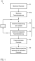
- Figure 1 shows a flow diagram of the method 100 for minimizing a deviation of a physical parameter of a blow molded container from a setpoint according to an embodiment.
- a blow molding machine is provided to produce the containers, and the physical properties of the container can be influenced by varying a machine parameter of the blow molding machine.
- other disturbance variables such as an environmental condition or a property of the preform from which the container is made, can also have an influence on the physical properties of the container.
- a blow molding machine which is designed to carry out the process Figure 1 is to be carried out in connection with the Figure 3 described.
- the method described is to specify a model by means of which the deviation of the physical parameter (for example a size characteristic of the wall or bottom thickness of a container) of a blow-molded container from a target value can be kept as low as possible by the targeted adjustment of a machine parameter.
- the model can be designed to keep the deviation of the physical parameter as low as possible even under changing conditions (disturbances) by specifically adjusting the machine parameter.
- the machine parameter can be, for example, a heating output of a heating device for heating the preform, a duty cycle of the heating device, a temperature profile in the preform generated by the heating device, a pre- or blowing pressure, a pre- or blowing pressure profile, a Pre- or a blowing time, the temperature of a blow mold and/or a stretching speed.
- a disturbance variable should basically be understood as any influence on the physical parameters of the container that is not directly caused by the operation of the machine and thus the machine parameters discussed above.
- the term physical parameter can also be understood, for example, as a quantity characterizing the physical parameter of a container, such as an optical parameter, which, for example, is a proportion of an intensity of electromagnetic radiation transmitted through a wall or floor thickness to an intensity of electromagnetic radiation irradiated onto the floor or wall thickness Radiation or a size of the injection lens measured using image processing.
- the disturbance may be an environmental condition or a property of the preform from which the container is made.
- the environmental condition can be, for example, an ambient temperature, an ambient humidity or an ambient pressure.
- the property of the preform can be, for example, a material composition of the preform or a material property of the preform, such as a viscosity, a copolymer content, a moisture content or degree of crystallization.
- the target value hereinafter indicates the value of the physical parameter to be obtained during the manufacture of the container.
- a physical parameter of a container is determined, which is assigned to a specific machine parameter of a blow molding machine.
- a disturbance variable assigned to the machine parameter of the blow molding machine can also be determined.
- the machine parameter of the blow molding machine can be set to a specific target value and, after the target value has been reached, the physical parameter of a container can be recorded and measured.
- the measurement of a disturbance variable can also be provided.
- the change in the machine parameter value 101a is initialized with a start value before the start of the iteration process 102.
- the starting value of the change in the machine parameter value is determined based on the physical parameter determined in the first method step 101 and a target value for the physical parameter.
- the change in the machine parameter value can be determined based on a difference between the setpoint and the measured value of the physical parameter.
- an optimal machine parameter is determined based on an iteration process, if necessary based on the physical parameter and the optional disturbance variable, by means of which a minimum deviation from the target value of the physical parameter of a blow-molded container can be achieved.
- the iteration process includes two iteration steps 103 and 104.
- a deviation from the target value of the physical parameter of a blow-molded container is determined based on a change in the machine parameter, possibly taking the disturbance variable(s) into account.
- the starting value can be determined, for example, by means of a neural network, which determines the starting value based on the physical parameters, machine parameters and disturbance variables determined by measurement in the first method step 101.
- the neural network is preferably an already trained or learned neural network that has been specifically trained with data/information suitable for determining the change in the machine parameters.
- the training/learning of the neural network can be carried out using an automated statistical test plan (DOE), in which various machine parameter values are automatically approached and an associated physical parameter of a container and a disturbance variable are measured.
- DOE automated statistical test plan
- an adjusted change in a machine parameter is determined based on the deviation of the physical parameter of a blow-molded container from a target value determined in the first iteration step 103.
- the adapted change in the machine parameter determined by the second iteration step 104 is then made available as input to the first iteration step 103, in which a new deviation from the target value of the physical parameter is determined based on the adapted change in the machine parameter value. Based on this new specific deviation from the setpoint of the physical parameter, an adapted change in the machine parameter value is then determined again in the second iteration step, if necessary taking the disturbance variables into account.
- n can be used to specify after how many iteration steps the iteration process is ended.
- n is an integer greater than zero, but can also take on any other value as long as a comparison to a continuous index of iteration steps is possible.
- n can be a value of 10.
- a lower or higher value for n such as 3, 5, 20, 50 or 100, can also be provided. Any other number is also conceivable, and the number of iteration steps can preferably be chosen so that the time required to carry out all n iteration steps is, if possible, below a limit value T.
- T can, for example, be selected depending on the throughput or response time of the blow molding machine to ensure that the machine parameter is adjusted as much as possible takes place before further containers have been formed.
- n can be chosen so that T ⁇ 50ms or T ⁇ 100ms.
- a dynamic limit value is also conceivable, which is determined dynamically during the iteration process.
- the iteration process is only ended when the change in the deviation of the physical parameter from the target value over a number of i iteration steps is smaller than a predetermined limit value and / or when the deviation of the target value over a number of i iteration steps is below a limit value d , which is predetermined, for example, by the production accuracy to be achieved.
- the physical parameter already converges to the target value and further calculations only improve the result to an extent that is irrelevant to the production accuracy to be achieved, so that further iterations can improve the result, but are no longer relevant to the accuracy of the products to be achieved are.
- an optimal machine parameter can finally be obtained 105.
- the iteration process 102 is based on a reinforcement learning model.
- the reinforcement learning model includes two components, based on the interaction of which the optimal machine parameter can be obtained to minimize the deviation of the physical parameter of a blow-molded container from a target value.
- the first component comprises a predictive model or a first neural network and the second component comprises a third neural network.
- the first component can be designed to determine a deviation of a physical parameter from a target value based on a change in a machine parameter.
- the second component can in turn be designed to determine an adjusted change in a machine parameter in order to minimize the deviation of the physical parameter determined by the first component.
- the third neural network can be a neural network trained using reinforcement learning. The training process of the third neural network using the reinforcement learning model is related to the Figure 2 described in more detail.
- obtaining the optimal machine parameter 105 is based on the determination of an optimal adapted change, which in turn is based on a minimum deviation from the setpoint of the physical parameter from the set of determined deviations from the setpoint of the physical parameter.
- Determining the optimal adjusted change may include, for example, that from the Set of all iteratively determined deviations of the physical parameter from the setpoint and the associated adjusted machine parameters, the index m is determined for which the deviation of the physical parameter from the setpoint is minimal.
- the determination of the optimal adjusted changes can be done by summation over all adjusted changes with indices 1 ... m . Based on the optimal adjusted change thus determined, the optimal machine parameter can be obtained.
- the optimal machine parameter can then be passed on to the blow molding machine 106.
- executable code is generated for the first and second components in order to carry out the iteration process during operation of the blow molding machine by means of a control unit of the blow molding machine, which can include a CPU and a GPU. It can be provided that the executable code is executed by the CPU of the control unit and/or by the GPU of the control unit.
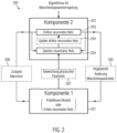
- Figure 2 shows a training process of the third neural network based on a reinforcement learning model 200.
- the trained third neural network can then be interacted with the first neural network, as described in the context of Figure 1 is described, determine an optimal machine parameter to minimize the deviation of the physical parameter from a target value.
- the reinforcement learning model 200 includes a first 201 and a second component 202, which interact with each other.
- the first component 201 can be a predictive model or a first neural network or can include a predictive model or a first neural network.
- the predictive model can be designed, for example, as a decision tree, as a random decision tree, as a reinforced decision tree, as a polynomial model with different orders and interactions or as a linear or non-linear ARX model.
- the first component 201 of the reinforcement learning model thus establishes a connection between the machine parameter, the disturbance variable and the deviation of the physical parameter of a container from a target value.
- the first component 201 is therefore designed to take the influence of a change of the machine parameter and/or the disturbance variable on the physical parameter of a container.
- the first component is also known as the environment and the second component as the agent.
- the first component 201 provides the second component 202 with information 207, 208, which is processed by the second component 202. Based on the processing information, the second component 202 generates an output 206, which in turn is made available to the first component 201.
- the first component provides the second component with a state of the blow molding machine 208 and a deviation of the physical parameter from a setpoint 207. The goal of the iteration process is to minimize the deviation of the physical parameter 207.
- the second component 202 generates an adapted change in a machine parameter value 206 based on the input 207, 208 provided.
- This value is in turn passed on to the first component 201 and the first component 201 determines one of this adapted change based on the adapted change in the machine parameter value assigned deviation of the physical parameter from a setpoint and a machine state.
- the first component 201 passes the values determined in this way to the second component 202. It can be provided that the iteration process just described is repeated n times before it is ended. Alternatively, it can also be provided that the iteration process is only ended when the change in the deviation from the setpoint value over a number of i iteration steps is smaller than a predetermined limit value.
- the second component 202 includes a second neural network 204 and a third neural network 203.
- the second neural network is a trained neural network, which is designed to establish a connection between the machine state 208 transferred by the first component 201, the deviation of the physical parameter from a target value 207 and the adapted change in the machine parameter 206.
- the second neural network is also designed to update the third neural network based on the information 206, 207 received from the first component, so that it determines a new adapted change in the machine parameter.
- the second neural network 204 can be designed as a reinforcement learning algorithm.
- the third neural network 203 is trained on the deviation of the physical parameter from a setpoint 207 by means of an adjusted change in the machine parameter 206 to minimize the deviation of the physical parameter from a setpoint.
- the first neural network of the first component 201 and the third neural network 203 of the in the Figure 2 Reinforcement learning model described in accordance with the Figure 1 described embodiment can be used on a blow molding machine.
- the second neural network 204 of the second component 203 is only intended for the training process of the third neural network 203 described above. That in the Figure 1
- the method described for minimizing the deviation of a physical parameter from a target value is preferably carried out only based on the interaction of the first neural network of the first component 201 and the fully trained third neural network 203 of the second component 202.
- the first component 201 passes on the specific deviation of the physical parameter 207 and the state of the machine 208 directly to the trained third neural network 203 without these being previously processed by the second neural network 204.
- the third neural network 203 determines an adapted change in the machine parameter 206 directly based on the parameters received from the first component 201, which is then passed on to the first component 201.
- this iteration process can be carried out until a static limit value n is reached, or until the change in the deviation of the physical parameter from the setpoint value over a number of i iteration steps is smaller than a predetermined limit value and / or if the deviation of the setpoint value over a number of i iteration steps is below a limit value d , which is predetermined, for example, by the production accuracy to be achieved.
- a limit value d which is predetermined, for example, by the production accuracy to be achieved.
- the optimal machine parameters 105 described can be obtained, which can then be transferred to the blow molding machine. Based on this, a machine parameter of the blow molding machine can be adjusted 106 and a container can be created which has a minimal deviation of a physical parameter from a target value.
- Figure 3 shows a blow molding machine 300 for producing containers 302 from preforms 301.
- the one in the Figure 3 The blow molding machine shown is designed to carry out a process in accordance with that in the Figures 1 and 2 described embodiments.
- the blow molding machine according to the Figure 3
- the embodiment shown includes a sensor device 305, a control device 306, optionally a device 303 for pre-treating the preforms and a blow molding device 304.
- the optional device 303 for pre-treating the preforms is arranged upstream of the blow molding device 304.
- the preforms 301/containers 302 can be transported through the blow molding machine 300 by means of one or more transport devices 312.
- the transport device 312 is shown as a linear transport device.
- the preforms/containers can also be transported through the blow molding machine by means of one or more rotary units, in particular transport stars, which can transport the preforms and/or containers, for example using the neck handling method.
- the optional device 303 for pre-treating the preforms is arranged along the circumference of a first rotary unit and the blow molding device 304 is arranged along the circumference of a second rotary unit.
- the two rotary units are also arranged such that the first rotary unit is arranged upstream of the second rotary unit.
- the pretreatment device 303 can be a heating device by means of which the preforms can be heated to a specific target temperature. This can be realized, for example, by means of one or more heating lamps, which can be designed, for example, as infrared lamps.
- the heating device can also be designed to generate a specific temperature profile, so that the temperature of the preform is described not only by a temperature, but by a temperature profile (for example along the length of the preform).
- the preform is exposed to electromagnetic radiation, such as microwave radiation, for heating.
- the electromagnetic field which is responsible for heating the preform, is influenced by adjustable functional units (eg sliders) in such a way that a specific temperature profile can be generated on the preform using the electromagnetic field.
- the functional units can be controlled via a control unit 306.
- a resonator which is designed to generate electromagnetic radiation of a specific field strength distribution and can be controlled by means of the control unit 306, can be provided.
- the control device 306 for controlling the functional units or the resonator can be connected to a sensor device 305.
- the control device 306 can thus evaluate the condition of the container using the data received from the sensor device 305, which data can be, for example, the physical parameter of the container, and, if necessary, the temperature profile of the preform by controlling the functional units or the resonator adjust so that the container meets the required quality criteria.
- the device for pre-treatment 303 is designed as a laser heater.
- the control device 306 based on the data determined by the sensor device 305, parameters of the laser heating such as a power, a pulse duration, a repetition rate, a wavelength, a coherence length, a polarization, a beam diameter, etc Energy density, a beam profile, a divergence or a spot size can be adjusted in such a way as to create a specific temperature profile in the preform.
- the laser heating can be controlled by the control device 306 based on the data determined by the sensor device 305, which may include, for example, the physical parameter of the container, in order to generate a specific temperature profile in the container, so that containers can be manufactured with the required quality criteria .
- the heated preforms 301 are then transported into the blow molding device 304.
- the blow molding device preferably comprises a blow mold and a device for applying blown air to the preform.
- the heated preforms are transferred to a blow mold and blown air is applied, which leads to an extrusion of the preforms in the blow mold.
- the blow molding device can be a stretch blowing device or an extrusion blowing device.
- stretch blow molding in addition to extruding the preform with blown air, it is stretched in the longitudinal direction by introducing a stretching rod.
- extrusion blowing the preform is only subjected to blown air in order to cause it to be shaped into a container in the mold.
- the container is removed from the blow mold.
- the container is guided through a cooling device.
- a deviation in a physical parameter of the container is then determined using a sensor device 305.
- the device can be designed to determine a size characteristic of the wall thickness of a container, a wall thickness, a size characteristic of the bottom thickness, a bottom thickness and/or a molecular orientation of the container.
- the wall thickness characteristic size, the wall thickness, the bottom thickness characteristic size, the bottom thickness and/or the molecular orientation of a container are directly related to the maximum top and side load of a container and are therefore particularly suitable parameters for determining the quality of a container blow molded container.
- the sensor device 305 is also designed to determine at least one machine parameter of the blow molding machine and/or the device for pretreating the preforms.
- the machine parameters can also be stored in a memory of a control device 306, which is designed to control the blow molding machine.
- a metrological determination of the machine parameters by the sensor device 305 is not necessary and the at least one machine parameter can be obtained, for example, from the memory. This should also be understood as determining a machine parameter.
- the sensor device 305 can be designed to measure at least one disturbance variable.
- the sensor device may include a first sensor for determining a machine parameter 308, 309, a second sensor for measuring a deviation of a physical parameter of a container 310 and a third sensor for measuring a disturbance variable 307.
- the machine parameter and the disturbance variable are parameters that have a direct influence on the physical parameter.
- the disturbance variable can be, for example, an environmental condition or a property of the preform from which the container is made.
- the second sensor can be, for example, an ultrasonic sensor or a spectroscopic sensor for measuring a size characteristic of a wall thickness of a container, a wall thickness, a size characteristic of a bottom thickness of a container, a bottom thickness of a container, or a spectroscopic sensor for measuring a molecular orientation of the container .
- the spectroscopic sensor for measuring the quantity characteristic of the wall or floor thickness can, for example, be designed to detect a portion of an electromagnetic intensity transmitted through a wall or floor thickness Radiation is determined by an intensity of electromagnetic radiation irradiated on the floor or wall thickness.
- the characteristic size for the wall or bottom thickness can also depend on other parameters of the container, such as a material composition.
- the third sensor for measuring a disturbance variable can be, for example, a sensor for measuring an environmental condition. This can be, for example, a temperature, a humidity or a pressure sensor.
- the third sensor for measuring a disturbance variable can also be designed as a sensor for measuring a property of the preform.
- the sensor can be a spectroscopic sensor for determining a material composition or a degree of crystallization of a preform.
- the sensor device 305 is also designed to pass on the data recorded by measurement to a control device 306.
- the control device 306 is designed in the Figures 1 and 2 to carry out the method described in accordance with each of the embodiments described in this context.
- the control device can be assigned directly to the blow molding machine. However, it can also be an external control device. In principle, the control device can be designed as a computer or server.
- the control device 306 is in particular designed to determine the influence of a change in the machine parameter value and/or a disturbance variable on the physical parameter of a container based on an iteration process. Using the iteration process, the controller 306 may determine an optimal machine parameter value to achieve a minimum deviation from the setpoint of the physical parameter. In a first iteration step, the control device 306 determines a deviation from the setpoint of the physical parameter of a blow-molded container based on a change in the machine parameter. In one embodiment, it can be provided that the change in the machine parameter is transferred to the control device before the start of the iteration process and that it is initialized with a starting value.
- the controller 306 determines an adjusted change in a machine parameter value based on the determined deviation of the physical parameter from the setpoint.
- the control device can use the two associated with the Figure 1 include the neural networks described. Based on the determined by the iteration process With the adapted change, the control device can obtain an optimal machine parameter, based on which the control device controls the blow molding machine in order to minimize the deviation of the physical parameter of the container from a target value.
Landscapes
- Engineering & Computer Science (AREA)
- Artificial Intelligence (AREA)
- Evolutionary Computation (AREA)
- Physics & Mathematics (AREA)
- General Physics & Mathematics (AREA)
- Health & Medical Sciences (AREA)
- Theoretical Computer Science (AREA)
- Software Systems (AREA)
- Manufacturing & Machinery (AREA)
- Mechanical Engineering (AREA)
- Life Sciences & Earth Sciences (AREA)
- General Health & Medical Sciences (AREA)
- Medical Informatics (AREA)
- Biomedical Technology (AREA)
- Biophysics (AREA)
- Computational Linguistics (AREA)
- Data Mining & Analysis (AREA)
- Automation & Control Theory (AREA)
- Molecular Biology (AREA)
- Computing Systems (AREA)
- General Engineering & Computer Science (AREA)
- Mathematical Physics (AREA)
- Computer Vision & Pattern Recognition (AREA)
- Blow-Moulding Or Thermoforming Of Plastics Or The Like (AREA)
Applications Claiming Priority (1)
| Application Number | Priority Date | Filing Date | Title |
|---|---|---|---|
| DE102022121954.2A DE102022121954A1 (de) | 2022-08-31 | 2022-08-31 | Verfahren und Vorrichtung zum Minimieren einer Abweichung eines physischen Parameters eines blasgeformten Behälters von einem Sollwert |
Publications (3)
| Publication Number | Publication Date |
|---|---|
| EP4331809A1 true EP4331809A1 (fr) | 2024-03-06 |
| EP4331809B1 EP4331809B1 (fr) | 2025-06-11 |
| EP4331809C0 EP4331809C0 (fr) | 2025-06-11 |
Family
ID=87845482
Family Applications (1)
| Application Number | Title | Priority Date | Filing Date |
|---|---|---|---|
| EP23193373.0A Active EP4331809B1 (fr) | 2022-08-31 | 2023-08-25 | Procédé et dispositif pour minimiser l'écart d'un paramètre physique d'un récipient moulé par soufflage d'une valeur de consigne |
Country Status (4)
| Country | Link |
|---|---|
| US (1) | US20240069504A1 (fr) |
| EP (1) | EP4331809B1 (fr) |
| CN (1) | CN117621416A (fr) |
| DE (1) | DE102022121954A1 (fr) |
Families Citing this family (3)
| Publication number | Priority date | Publication date | Assignee | Title |
|---|---|---|---|---|
| DE102024115905A1 (de) * | 2024-06-07 | 2025-12-11 | Krones Aktiengesellschaft | Computer-implementiertes Verfahren zum Erzeugen einer digitalen statischen Versuchsplanung |
| CN120002997B (zh) * | 2025-04-21 | 2025-06-20 | 上海宝柏新材料股份有限公司 | 一种边缘强化吹塑面板温度分布控制方法及系统 |
| CN121515446B (zh) * | 2026-01-14 | 2026-04-14 | 成都紫江包装有限公司 | 一种pet塑料瓶智能吹塑成型与壁厚闭环控制系统 |
Citations (7)
| Publication number | Priority date | Publication date | Assignee | Title |
|---|---|---|---|---|
| DE10000859A1 (de) * | 1999-04-23 | 2000-10-26 | Carsten Duesterhoeft | Automatisiertes Verfahren und Vorrichtung zum spanlosen Umformen eines Körpers |
| EP2470348B1 (fr) * | 2009-08-25 | 2014-04-09 | KHS Corpoplast GmbH | Procédé et dispositif de moulage par soufflage de contenants |
| EP1998950B1 (fr) | 2006-03-29 | 2014-10-29 | KHS Corpoplast GmbH | PROCEDE ET DISPOSITIF DE FORMAge-SOUFFLAGE DE RECIPIENTS PAR RECOURS A LA MESURE DE L'EPAISSEUR DE PAROIS DE L'OBJET FACONNE |
| US20160136868A1 (en) * | 2014-11-18 | 2016-05-19 | Krones Ag | Method for starting up a blow moulding machine, and system including a blow moulding machine |
| DE10165127B3 (de) * | 2001-04-04 | 2017-05-18 | Krones Aktiengesellschaft | Verfahren zur Steuerung eines Blasvorgangs bei der Herstellung von Behältern aus einem thermoplastischen Material |
| WO2017144145A1 (fr) * | 2016-02-23 | 2017-08-31 | Krones Ag | Procédé de fonctionnement d'une installation de traitement de récipient avec élaboration d'une prescription pour la commande |
| WO2020226921A1 (fr) * | 2019-05-07 | 2020-11-12 | Agr International, Inc. | Entretien préventif prédictif pour processus de production de formation de récipient |
Family Cites Families (9)
| Publication number | Priority date | Publication date | Assignee | Title |
|---|---|---|---|---|
| DE10116665B4 (de) | 2001-04-04 | 2015-10-29 | Krones Aktiengesellschaft | Verfahren zur Steuerung eines Blasvorgangs bei der Herstellung von Behältern aus einem thermoplastischen Material |
| DE102007001024B4 (de) | 2007-01-02 | 2008-10-02 | Siemens Ag | Verfahren zur rechnergestützten Regelung und/oder Steuerung eines technischen Systems insbesondere einer Gasturbine |
| DE102008057999A1 (de) | 2008-11-13 | 2010-05-20 | Khs Corpoplast Gmbh & Co. Kg | Verfahren und Vorrichtung zur Blasformung von Behältern |
| JP6346128B2 (ja) | 2015-07-28 | 2018-06-20 | ファナック株式会社 | 最適な操作条件を算出できる射出成形システム及び機械学習器 |
| EP3696737B1 (fr) | 2016-11-03 | 2022-08-31 | Deepmind Technologies Limited | Réseaux neuronaux de sélection d'action d'entraînement |
| WO2018142212A1 (fr) | 2017-01-31 | 2018-08-09 | Deepmind Technologies Limited | Apprentissage par renforcement économe en données pour tâches de commande continue |
| CN108830376B (zh) * | 2018-06-13 | 2021-12-14 | 中国科学技术大学 | 针对时间敏感的环境的多价值网络深度强化学习方法 |
| US11914350B2 (en) | 2018-08-09 | 2024-02-27 | Siemens Aktiengesellschaft | Manufacturing process control using constrained reinforcement machine learning |
| US20220036186A1 (en) | 2020-07-30 | 2022-02-03 | Waymo Llc | Accelerated deep reinforcement learning of agent control policies |
-
2022
- 2022-08-31 DE DE102022121954.2A patent/DE102022121954A1/de active Pending
-
2023
- 2023-08-24 CN CN202311071843.6A patent/CN117621416A/zh active Pending
- 2023-08-25 EP EP23193373.0A patent/EP4331809B1/fr active Active
- 2023-08-29 US US18/457,959 patent/US20240069504A1/en active Pending
Patent Citations (7)
| Publication number | Priority date | Publication date | Assignee | Title |
|---|---|---|---|---|
| DE10000859A1 (de) * | 1999-04-23 | 2000-10-26 | Carsten Duesterhoeft | Automatisiertes Verfahren und Vorrichtung zum spanlosen Umformen eines Körpers |
| DE10165127B3 (de) * | 2001-04-04 | 2017-05-18 | Krones Aktiengesellschaft | Verfahren zur Steuerung eines Blasvorgangs bei der Herstellung von Behältern aus einem thermoplastischen Material |
| EP1998950B1 (fr) | 2006-03-29 | 2014-10-29 | KHS Corpoplast GmbH | PROCEDE ET DISPOSITIF DE FORMAge-SOUFFLAGE DE RECIPIENTS PAR RECOURS A LA MESURE DE L'EPAISSEUR DE PAROIS DE L'OBJET FACONNE |
| EP2470348B1 (fr) * | 2009-08-25 | 2014-04-09 | KHS Corpoplast GmbH | Procédé et dispositif de moulage par soufflage de contenants |
| US20160136868A1 (en) * | 2014-11-18 | 2016-05-19 | Krones Ag | Method for starting up a blow moulding machine, and system including a blow moulding machine |
| WO2017144145A1 (fr) * | 2016-02-23 | 2017-08-31 | Krones Ag | Procédé de fonctionnement d'une installation de traitement de récipient avec élaboration d'une prescription pour la commande |
| WO2020226921A1 (fr) * | 2019-05-07 | 2020-11-12 | Agr International, Inc. | Entretien préventif prédictif pour processus de production de formation de récipient |
Also Published As
| Publication number | Publication date |
|---|---|
| CN117621416A (zh) | 2024-03-01 |
| EP4331809B1 (fr) | 2025-06-11 |
| US20240069504A1 (en) | 2024-02-29 |
| EP4331809C0 (fr) | 2025-06-11 |
| DE102022121954A1 (de) | 2024-02-29 |
Similar Documents
| Publication | Publication Date | Title |
|---|---|---|
| EP4331809B1 (fr) | Procédé et dispositif pour minimiser l'écart d'un paramètre physique d'un récipient moulé par soufflage d'une valeur de consigne | |
| EP2207664B1 (fr) | Souffleuse pour des récipients en plastique et procédé de commande correspondant | |
| EP4219120B1 (fr) | Dispositif et procédé de chauffage d'ébauches en plastique au moyen d'une détection de température à résolution spatiale | |
| EP3964349B1 (fr) | Dispositif et procédé de chauffage de préformes en matière plastique à détection de température à résolution espace | |
| EP3560679B1 (fr) | Procédé de mise en service d'une machine de formage par soufflage et installation comprenant une machine de formage par soufflage | |
| DE102017120201A1 (de) | Selbstlernende Blasmaschine mittels Bildauswertung | |
| DE102021108790A1 (de) | Verfahren zum Auswerten defekter Behältnisse und Defektauswerteeinrichtung für eine Behältnisbehandlungsanlage | |
| DE10116665B4 (de) | Verfahren zur Steuerung eines Blasvorgangs bei der Herstellung von Behältern aus einem thermoplastischen Material | |
| EP4197740B1 (fr) | Dispositif et procédé de chauffage d'ébauches en plastique avec réglage de la puissance de chauffage | |
| WO1992007701A1 (fr) | Procede et dispositif de production d'extrudats plats a section transversale annulaire | |
| EP4201639B1 (fr) | Procédé et dispositif de chauffage d'ébauches en plastique au moyen d'une mesure d'absorption | |
| CH716122A1 (de) | Verfahren zum Betreiben einer Vorrichtung zur Herstellung eines Produktes, Computerprogrammprodukt und Vorrichtung zum Herstellen eines Produktes. | |
| DE102019128501A1 (de) | Herstellungsverfahren für Kunststoffbehälter und Blasformmaschine | |
| DE3416781A1 (de) | Verfahren zum herstellen von vorformlingen aus thermoplastischem kunststoff fuer das blasformen von hohlkoerpern | |
| EP4173798A1 (fr) | Procédé et dispositif de déformation d'ébauches en plastique en récipients en plastique dotés d'une évaluation de forme d'écoulement | |
| DE102017120861A1 (de) | Verfahren und Vorrichtung zur Herstellung von Behältern aus thermoplastischem Material | |
| EP4494841B1 (fr) | Circuit de commande pour un dispositif de chauffage de préformes et comprenant une machine de soufflage pour fabriquer des récipients à partir de préformes préchauffées, dispositif comprenant un dispositif de chauffage pour préformes et procédé de fabrication de récipients | |
| EP4660730A1 (fr) | Procédé mis en oeuvre par ordinateur pour générer une planification d'expérience statique numérique | |
| DE102023119045A1 (de) | Behälterbehandlungsanlage zum Regeln einer Temperatur eines Vorformlings | |
| DE10165127B3 (de) | Verfahren zur Steuerung eines Blasvorgangs bei der Herstellung von Behältern aus einem thermoplastischen Material | |
| EP4566795A1 (fr) | Procédé et dispositif de fabrication de récipients en matière plastique | |
| EP4556197A1 (fr) | Procédé de régulation d'une installation de traitement de récipients et dispositif de régulation pour la mise en oeuvre du procédé | |
| EP4494842A1 (fr) | Installation de traitement de récipients et procédé de fabrication et de traitement d'une préforme | |
| DE102024105725A1 (de) | Vorrichtung und Verfahren zum Behandeln von Vorformlingen | |
| DE102023134557A1 (de) | Vorrichtung und Verfahren zur Herstellung von Behältern |
Legal Events
| Date | Code | Title | Description |
|---|---|---|---|
| PUAI | Public reference made under article 153(3) epc to a published international application that has entered the european phase |
Free format text: ORIGINAL CODE: 0009012 |
|
| STAA | Information on the status of an ep patent application or granted ep patent |
Free format text: STATUS: THE APPLICATION HAS BEEN PUBLISHED |
|
| AK | Designated contracting states |
Kind code of ref document: A1 Designated state(s): AL AT BE BG CH CY CZ DE DK EE ES FI FR GB GR HR HU IE IS IT LI LT LU LV MC ME MK MT NL NO PL PT RO RS SE SI SK SM TR |
|
| STAA | Information on the status of an ep patent application or granted ep patent |
Free format text: STATUS: REQUEST FOR EXAMINATION WAS MADE |
|
| 17P | Request for examination filed |
Effective date: 20240904 |
|
| RBV | Designated contracting states (corrected) |
Designated state(s): AL AT BE BG CH CY CZ DE DK EE ES FI FR GB GR HR HU IE IS IT LI LT LU LV MC ME MK MT NL NO PL PT RO RS SE SI SK SM TR |
|
| GRAP | Despatch of communication of intention to grant a patent |
Free format text: ORIGINAL CODE: EPIDOSNIGR1 |
|
| STAA | Information on the status of an ep patent application or granted ep patent |
Free format text: STATUS: GRANT OF PATENT IS INTENDED |
|
| RIC1 | Information provided on ipc code assigned before grant |
Ipc: B29L 31/00 20060101ALN20250130BHEP Ipc: B29C 49/36 20060101ALN20250130BHEP Ipc: B29C 49/06 20060101ALN20250130BHEP Ipc: B29C 49/78 20060101AFI20250130BHEP |
|
| INTG | Intention to grant announced |
Effective date: 20250214 |
|
| GRAS | Grant fee paid |
Free format text: ORIGINAL CODE: EPIDOSNIGR3 |
|
| GRAA | (expected) grant |
Free format text: ORIGINAL CODE: 0009210 |
|
| STAA | Information on the status of an ep patent application or granted ep patent |
Free format text: STATUS: THE PATENT HAS BEEN GRANTED |
|
| AK | Designated contracting states |
Kind code of ref document: B1 Designated state(s): AL AT BE BG CH CY CZ DE DK EE ES FI FR GB GR HR HU IE IS IT LI LT LU LV MC ME MK MT NL NO PL PT RO RS SE SI SK SM TR |
|
| REG | Reference to a national code |
Ref country code: GB Ref legal event code: FG4D Free format text: NOT ENGLISH |
|
| REG | Reference to a national code |
Ref country code: CH Ref legal event code: EP |
|
| REG | Reference to a national code |
Ref country code: IE Ref legal event code: FG4D Free format text: LANGUAGE OF EP DOCUMENT: GERMAN |
|
| REG | Reference to a national code |
Ref country code: DE Ref legal event code: R096 Ref document number: 502023001136 Country of ref document: DE |
|
| U01 | Request for unitary effect filed |
Effective date: 20250701 |
|
| U07 | Unitary effect registered |
Designated state(s): AT BE BG DE DK EE FI FR IT LT LU LV MT NL PT RO SE SI Effective date: 20250707 |
|
| U20 | Renewal fee for the european patent with unitary effect paid |
Year of fee payment: 3 Effective date: 20250709 |
|
| PG25 | Lapsed in a contracting state [announced via postgrant information from national office to epo] |
Ref country code: ES Free format text: LAPSE BECAUSE OF FAILURE TO SUBMIT A TRANSLATION OF THE DESCRIPTION OR TO PAY THE FEE WITHIN THE PRESCRIBED TIME-LIMIT Effective date: 20250611 |
|
| PG25 | Lapsed in a contracting state [announced via postgrant information from national office to epo] |
Ref country code: GR Free format text: LAPSE BECAUSE OF FAILURE TO SUBMIT A TRANSLATION OF THE DESCRIPTION OR TO PAY THE FEE WITHIN THE PRESCRIBED TIME-LIMIT Effective date: 20250912 Ref country code: NO Free format text: LAPSE BECAUSE OF FAILURE TO SUBMIT A TRANSLATION OF THE DESCRIPTION OR TO PAY THE FEE WITHIN THE PRESCRIBED TIME-LIMIT Effective date: 20250911 |
|
| PG25 | Lapsed in a contracting state [announced via postgrant information from national office to epo] |
Ref country code: HR Free format text: LAPSE BECAUSE OF FAILURE TO SUBMIT A TRANSLATION OF THE DESCRIPTION OR TO PAY THE FEE WITHIN THE PRESCRIBED TIME-LIMIT Effective date: 20250611 |
|
| PG25 | Lapsed in a contracting state [announced via postgrant information from national office to epo] |
Ref country code: RS Free format text: LAPSE BECAUSE OF FAILURE TO SUBMIT A TRANSLATION OF THE DESCRIPTION OR TO PAY THE FEE WITHIN THE PRESCRIBED TIME-LIMIT Effective date: 20250911 |
|
| PG25 | Lapsed in a contracting state [announced via postgrant information from national office to epo] |
Ref country code: IS Free format text: LAPSE BECAUSE OF FAILURE TO SUBMIT A TRANSLATION OF THE DESCRIPTION OR TO PAY THE FEE WITHIN THE PRESCRIBED TIME-LIMIT Effective date: 20251011 |
|
| PG25 | Lapsed in a contracting state [announced via postgrant information from national office to epo] |
Ref country code: SM Free format text: LAPSE BECAUSE OF FAILURE TO SUBMIT A TRANSLATION OF THE DESCRIPTION OR TO PAY THE FEE WITHIN THE PRESCRIBED TIME-LIMIT Effective date: 20250611 |
|
| PG25 | Lapsed in a contracting state [announced via postgrant information from national office to epo] |
Ref country code: CZ Free format text: LAPSE BECAUSE OF FAILURE TO SUBMIT A TRANSLATION OF THE DESCRIPTION OR TO PAY THE FEE WITHIN THE PRESCRIBED TIME-LIMIT Effective date: 20250611 |
|
| PG25 | Lapsed in a contracting state [announced via postgrant information from national office to epo] |
Ref country code: PL Free format text: LAPSE BECAUSE OF FAILURE TO SUBMIT A TRANSLATION OF THE DESCRIPTION OR TO PAY THE FEE WITHIN THE PRESCRIBED TIME-LIMIT Effective date: 20250611 |
|
| PG25 | Lapsed in a contracting state [announced via postgrant information from national office to epo] |
Ref country code: SK Free format text: LAPSE BECAUSE OF FAILURE TO SUBMIT A TRANSLATION OF THE DESCRIPTION OR TO PAY THE FEE WITHIN THE PRESCRIBED TIME-LIMIT Effective date: 20250611 |
|
| PLBI | Opposition filed |
Free format text: ORIGINAL CODE: 0009260 |
|
| REG | Reference to a national code |
Ref country code: CH Ref legal event code: L10 Free format text: ST27 STATUS EVENT CODE: U-0-0-L10-L00 (AS PROVIDED BY THE NATIONAL OFFICE) Effective date: 20260318 |
|
| PG25 | Lapsed in a contracting state [announced via postgrant information from national office to epo] |
Ref country code: MC Free format text: LAPSE BECAUSE OF FAILURE TO SUBMIT A TRANSLATION OF THE DESCRIPTION OR TO PAY THE FEE WITHIN THE PRESCRIBED TIME-LIMIT Effective date: 20250611 |
|
| PLAX | Notice of opposition and request to file observation + time limit sent |
Free format text: ORIGINAL CODE: EPIDOSNOBS2 |
|
| 26 | Opposition filed |
Opponent name: KHS GMBH Effective date: 20260310 |