EP4331889A1 - Ladesystem für ein elektrisches arbeitsfahrzeug und zugehöriges verfahren - Google Patents
Ladesystem für ein elektrisches arbeitsfahrzeug und zugehöriges verfahren Download PDFInfo
- Publication number
- EP4331889A1 EP4331889A1 EP23194375.4A EP23194375A EP4331889A1 EP 4331889 A1 EP4331889 A1 EP 4331889A1 EP 23194375 A EP23194375 A EP 23194375A EP 4331889 A1 EP4331889 A1 EP 4331889A1
- Authority
- EP
- European Patent Office
- Prior art keywords
- electric
- charging port
- electric power
- energy storage
- charging
- Prior art date
- Legal status (The legal status is an assumption and is not a legal conclusion. Google has not performed a legal analysis and makes no representation as to the accuracy of the status listed.)
- Pending
Links
Images


Classifications
-
- B—PERFORMING OPERATIONS; TRANSPORTING
- B60—VEHICLES IN GENERAL
- B60L—PROPULSION OF ELECTRICALLY-PROPELLED VEHICLES; SUPPLYING ELECTRIC POWER FOR AUXILIARY EQUIPMENT OF ELECTRICALLY-PROPELLED VEHICLES; ELECTRODYNAMIC BRAKE SYSTEMS FOR VEHICLES IN GENERAL; MAGNETIC SUSPENSION OR LEVITATION FOR VEHICLES; MONITORING OPERATING VARIABLES OF ELECTRICALLY-PROPELLED VEHICLES; ELECTRIC SAFETY DEVICES FOR ELECTRICALLY-PROPELLED VEHICLES
- B60L1/00—Supplying electric power to auxiliary equipment of vehicles
- B60L1/006—Supplying electric power to auxiliary equipment of vehicles to power outlets
-
- B—PERFORMING OPERATIONS; TRANSPORTING
- B60—VEHICLES IN GENERAL
- B60L—PROPULSION OF ELECTRICALLY-PROPELLED VEHICLES; SUPPLYING ELECTRIC POWER FOR AUXILIARY EQUIPMENT OF ELECTRICALLY-PROPELLED VEHICLES; ELECTRODYNAMIC BRAKE SYSTEMS FOR VEHICLES IN GENERAL; MAGNETIC SUSPENSION OR LEVITATION FOR VEHICLES; MONITORING OPERATING VARIABLES OF ELECTRICALLY-PROPELLED VEHICLES; ELECTRIC SAFETY DEVICES FOR ELECTRICALLY-PROPELLED VEHICLES
- B60L50/00—Electric propulsion with power supplied within the vehicle
- B60L50/50—Electric propulsion with power supplied within the vehicle using propulsion power supplied by batteries or fuel cells
- B60L50/60—Electric propulsion with power supplied within the vehicle using propulsion power supplied by batteries or fuel cells using power supplied by batteries
-
- B—PERFORMING OPERATIONS; TRANSPORTING
- B60—VEHICLES IN GENERAL
- B60L—PROPULSION OF ELECTRICALLY-PROPELLED VEHICLES; SUPPLYING ELECTRIC POWER FOR AUXILIARY EQUIPMENT OF ELECTRICALLY-PROPELLED VEHICLES; ELECTRODYNAMIC BRAKE SYSTEMS FOR VEHICLES IN GENERAL; MAGNETIC SUSPENSION OR LEVITATION FOR VEHICLES; MONITORING OPERATING VARIABLES OF ELECTRICALLY-PROPELLED VEHICLES; ELECTRIC SAFETY DEVICES FOR ELECTRICALLY-PROPELLED VEHICLES
- B60L53/00—Methods of charging batteries, specially adapted for electric vehicles; Charging stations or on-board charging equipment therefor; Exchange of energy storage elements in electric vehicles
- B60L53/10—Methods of charging batteries, specially adapted for electric vehicles; Charging stations or on-board charging equipment therefor; Exchange of energy storage elements in electric vehicles characterised by the energy transfer between the charging station and the vehicle
- B60L53/14—Conductive energy transfer
- B60L53/16—Connectors, e.g. plugs or sockets, specially adapted for charging electric vehicles
-
- B—PERFORMING OPERATIONS; TRANSPORTING
- B60—VEHICLES IN GENERAL
- B60L—PROPULSION OF ELECTRICALLY-PROPELLED VEHICLES; SUPPLYING ELECTRIC POWER FOR AUXILIARY EQUIPMENT OF ELECTRICALLY-PROPELLED VEHICLES; ELECTRODYNAMIC BRAKE SYSTEMS FOR VEHICLES IN GENERAL; MAGNETIC SUSPENSION OR LEVITATION FOR VEHICLES; MONITORING OPERATING VARIABLES OF ELECTRICALLY-PROPELLED VEHICLES; ELECTRIC SAFETY DEVICES FOR ELECTRICALLY-PROPELLED VEHICLES
- B60L58/00—Methods or circuit arrangements for monitoring or controlling batteries or fuel cells, specially adapted for electric vehicles
- B60L58/10—Methods or circuit arrangements for monitoring or controlling batteries or fuel cells, specially adapted for electric vehicles for monitoring or controlling batteries
- B60L58/12—Methods or circuit arrangements for monitoring or controlling batteries or fuel cells, specially adapted for electric vehicles for monitoring or controlling batteries responding to state of charge [SoC]
-
- H—ELECTRICITY
- H02—GENERATION; CONVERSION OR DISTRIBUTION OF ELECTRIC POWER
- H02J—ELECTRIC POWER NETWORKS; CIRCUIT ARRANGEMENTS OR SYSTEMS FOR SUPPLYING OR DISTRIBUTING ELECTRIC POWER; SYSTEMS FOR STORING ELECTRIC ENERGY
- H02J7/00—Circuit arrangements for charging or discharging batteries or for supplying loads from batteries
- H02J7/80—Circuit arrangements for charging or discharging batteries or for supplying loads from batteries including monitoring or indicating arrangements
-
- H—ELECTRICITY
- H02—GENERATION; CONVERSION OR DISTRIBUTION OF ELECTRIC POWER
- H02J—ELECTRIC POWER NETWORKS; CIRCUIT ARRANGEMENTS OR SYSTEMS FOR SUPPLYING OR DISTRIBUTING ELECTRIC POWER; SYSTEMS FOR STORING ELECTRIC ENERGY
- H02J7/00—Circuit arrangements for charging or discharging batteries or for supplying loads from batteries
- H02J7/90—Regulation of charging or discharging current or voltage
- H02J7/933—Regulation of charging or discharging current or voltage the cycle being controlled or terminated in response to electric parameters
-
- B—PERFORMING OPERATIONS; TRANSPORTING
- B60—VEHICLES IN GENERAL
- B60L—PROPULSION OF ELECTRICALLY-PROPELLED VEHICLES; SUPPLYING ELECTRIC POWER FOR AUXILIARY EQUIPMENT OF ELECTRICALLY-PROPELLED VEHICLES; ELECTRODYNAMIC BRAKE SYSTEMS FOR VEHICLES IN GENERAL; MAGNETIC SUSPENSION OR LEVITATION FOR VEHICLES; MONITORING OPERATING VARIABLES OF ELECTRICALLY-PROPELLED VEHICLES; ELECTRIC SAFETY DEVICES FOR ELECTRICALLY-PROPELLED VEHICLES
- B60L2200/00—Type of vehicles
- B60L2200/40—Working vehicles
-
- B—PERFORMING OPERATIONS; TRANSPORTING
- B60—VEHICLES IN GENERAL
- B60L—PROPULSION OF ELECTRICALLY-PROPELLED VEHICLES; SUPPLYING ELECTRIC POWER FOR AUXILIARY EQUIPMENT OF ELECTRICALLY-PROPELLED VEHICLES; ELECTRODYNAMIC BRAKE SYSTEMS FOR VEHICLES IN GENERAL; MAGNETIC SUSPENSION OR LEVITATION FOR VEHICLES; MONITORING OPERATING VARIABLES OF ELECTRICALLY-PROPELLED VEHICLES; ELECTRIC SAFETY DEVICES FOR ELECTRICALLY-PROPELLED VEHICLES
- B60L2240/00—Control parameters of input or output; Target parameters
- B60L2240/40—Drive Train control parameters
- B60L2240/54—Drive Train control parameters related to batteries
- B60L2240/547—Voltage
-
- Y—GENERAL TAGGING OF NEW TECHNOLOGICAL DEVELOPMENTS; GENERAL TAGGING OF CROSS-SECTIONAL TECHNOLOGIES SPANNING OVER SEVERAL SECTIONS OF THE IPC; TECHNICAL SUBJECTS COVERED BY FORMER USPC CROSS-REFERENCE ART COLLECTIONS [XRACs] AND DIGESTS
- Y02—TECHNOLOGIES OR APPLICATIONS FOR MITIGATION OR ADAPTATION AGAINST CLIMATE CHANGE
- Y02T—CLIMATE CHANGE MITIGATION TECHNOLOGIES RELATED TO TRANSPORTATION
- Y02T10/00—Road transport of goods or passengers
- Y02T10/60—Other road transportation technologies with climate change mitigation effect
- Y02T10/70—Energy storage systems for electromobility, e.g. batteries
Definitions
- the present disclosure generally relates to electric work vehicles and, more particularly, to systems and methods for charging electric work vehicles.
- backhoe loaders such as backhoe loaders, wheel loaders, skid steer loaders, compact track loaders, and the like
- work vehicles typically include one or more implements for carrying materials, such as gravel, sand, or dirt, around a worksite.
- backhoe loaders include a chassis, a loader assembly coupled to the front of the chassis, and a backhoe assembly coupled to the rear of the chassis.
- Electric work vehicles have generally relied on an internal combustion engine to power the vehicle.
- interest in electric work vehicles has increased.
- Electric work vehicles do not include an internal combustion engine. Instead, electric work vehicles rely on one or more electric motors powered by an energy storage device(s), such as a battery module, to power its components.
- an electric power source e.g., the power grid
- electric power sources at work sites are generally limited, particularly during the early phases of construction.
- other electrically powered devices e.g., power tools
- the present subject matter is directed to an electric work vehicle including a frame and a traction device coupled to the frame. Furthermore, the electric work vehicle includes an electric motor configured to drive the traction device and an energy storage device configured to supply electric energy to the electric motor. Additionally, the electric work vehicle includes an electric charging port configured to receive electric power from a power source, with the electric charging port being electrically coupled to the energy storage device. Moreover, the electric work vehicle includes an electric outlet configured to provide electric power to a remote device, with the electric outlet being electrically coupled to the electric charging port and the energy storage device. In addition, the electric work vehicle includes a computing system configured to control a distribution of the electric power received by the electric charging port between the energy storage device and the electric outlet.
- the present subject matter is directed to a system for charging an electric work vehicle.
- the system includes an electric motor configured to drive a traction device of the electric work vehicle and an energy storage device configured to supply electric energy to the electric motor.
- the system includes an electric charging port configured to receive electric power from a power source, with the electric charging port being electrically coupled to the energy storage device.
- the system includes an electric outlet configured to provide electric power to a remote device, with the electric outlet being electrically coupled to the electric charging port and the energy storage device.
- the system includes a computing system configured to control a distribution of the electric power received by the electric charging port between the energy storage device and the electric outlet.
- the present subject matter is directed to a method for charging an electric work vehicle.
- the electric work vehicle includes an electric motor configured to drive a traction device of the electric work vehicle and an energy storage device configured to supply electric energy to the electric motor.
- the method includes determining, with a computing system, a charging capacity of the energy storage device.
- the method includes determining, with the computing system, a charging capacity of electric power received by an electric charging port on the electric work vehicle.
- the electric charging port is configured to receive the electric power from a power source, with the electric charging port being electrically coupled to the energy storage device.
- the method includes controlling, with the computing system, a distribution of the electric power received by the electric charging port between the energy storage device and an electric outlet based on at least one of the determined charging capacity of the energy storage device or the determined charging capacity of the electric power received by an electric charging port.
- the electric outlet is configured to provide electric power to a remote device, with the electric outlet being electrically coupled to the electric charging port and the energy storage device.
- the present subject matter is directed to an electric work vehicle having a charging system and an associated method.
- the electric work vehicle includes one or more electric motors configured to drive one or more traction device(s) (e.g., a wheel(s), a track assembly(ies), etc.) of the electric work vehicle.
- the electric work vehicle includes one or more energy storage devices (e.g., a battery module) configured to supply electric energy to the electric motor(s).
- the electric work vehicle includes an electric charging port configured to receive electric power from a power source (e.g., the electric power grid).
- the electric charging port is electrically coupled to the energy storage device(s), thereby permitting at least a portion of the electric power received by the electric charging port to charge the energy storage device(s) in certain instances.
- the electric work vehicle includes an electric outlet configured to provide electric power to a remote device(s), such as a power tool(s).
- the electric outlet is electrically coupled to the electric charging port and the energy storage device, thereby permitting the electric outlet to receive electric power from the electric charging port and/or the energy storage device(s).
- a computing system is configured to control the distribution of the electric power received by the electric charging port between the energy storage device(s) and the electric outlet. Specifically, when a remote device(s) is not electrically coupled to the electric outlet, the computing system may control the distribution of the electric power such that the energy storage device(s) is charged by the electric power received by the electric charging port at the any rate within the capacity of the power source. Conversely, when a remote device(s) is electrically coupled to the electric outlet, the computing system may control the distribution of the electric power such that charging/operation of the remote device(s) is prioritized over charging of the energy storage device(s).
- the computing system may initiate the supply of additional power from the energy storage device(s) to meet the power draw requirement(s) of the remote device(s).
- the disclosed electric work vehicle, system, and method provide prioritized charging of remote device(s) (e.g., a power tool(s)), while still allowing for simultaneous charging of the energy storage device(s) of the electric work vehicle from a single power source when extra charging capacity is available.
- the disclosed electric work vehicle, system, and method allow for a single power source to charge multiple electrically powered devices (e.g., the electric work vehicle and the remote device(s)) in a minimum amount of time. This, in turn, improves work site productivity and simplifies management of the charging of such devices.
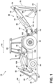
- FIG. 1 illustrates a side view of one embodiment of an electric work vehicle 10 in accordance with aspects of the present subject matter.
- the electric work vehicle 10 is configured as an electric backhoe loader (also often referred to as a "tractor-loader-backhoe” (TLB) or a “loader backhoe”).
- the electric work vehicle 10 may be configured as any other suitable type of electric work vehicle, such as another type of electric construction vehicle (e.g., a wheel loader, a skid-steer loader, a bulldozer, etc.), an electric agricultural vehicle (e.g., a tractor), and/or the like.
- the electric work vehicle 10 includes a chassis or frame 12 extending in a longitudinal direction (indicated by arrow 14 in FIG. 1 ) of the electric work vehicle 10 between a forward end 16 of the frame 12 and an aft end 18 of the frame 12.
- the chassis or frame 12 may be configured to support or couple to a plurality of components.
- a pair of steerable front traction devices e.g., front wheels 20 (one of which is shown)
- a pair of driven rear traction devices e.g., rear wheels 22 (one of which is shown)
- rear wheels 22 one of which is shown
- the wheels 20, 22 may support the electric work vehicle 10 relative to a ground surface 24 and move the electric work vehicle 10 along the ground surface 24 in a direction of travel, such as a forward direction of travel (indicated by arrow 26 in FIG. 1 ).
- the front wheels 20 may be driven in addition to or in lieu of the rear wheels 22.
- the front and/or rear traction devices may be configured as track assemblies (not shown).
- an operator's cab 28 may be supported by a portion of the frame 12 positioned between the forward and aft ends 16, 18 of the frame 12, and may house one or more operator control devices 30 (e.g., a joystick(s), a lever(s), and/or the like) for permitting an operator to control the operation of the electric work vehicle 10.
- operator control devices 30 e.g., a joystick(s), a lever(s), and/or the like
- the electric work vehicle 10 also includes a pair of work implement assemblies positioned at the opposed ends 16, 18 of the frame 12.
- the electric work vehicle 10 includes a loader assembly 40 supported by or relative the frame 12 at or adjacent to its forward end 16.
- the loader assembly 40 includes a loader arm 42 pivotably coupled or supported relative to the frame 12 at a loader arm pivot point 44, and a loader lift cylinder 46 secured between the loader arm 42 and the frame 12.
- extension/retraction of the loader lift cylinder 46 may result in the loader arm 42 pivoting upwards/downwards about its respective pivot point 44, thereby allowing the positioning of the loader arm 42 relative to both the frame 12 and the ground surface 24 to be adjusted, as desired.
- the loader assembly 40 further includes a first work implement 48, such as a loader bucket, coupled to the loader arm 42 at an implement pivot point 50, and a first implement tilt cylinder 52 secured between the work implement 48 (e.g., via a linkage(s) 54) and a portion of the loader arm 42.
- a first work implement 48 such as a loader bucket
- first implement tilt cylinder 52 secured between the work implement 48 (e.g., via a linkage(s) 54) and a portion of the loader arm 42.
- extension/retraction of the first implement tilt cylinder 52 may result in the first work implement 48 pivoting upwards/downwards relative to the loader arm 42 about its respective pivot point 50, thereby permitting the tilt angle or orientation of the implement 48 to be adjusted, as desired.
- the vertical positioning and orientation of the first work implement 48 may be adjusted to allow for the execution of one or more operations, such as one or more material-moving operations.
- the electric work vehicle 10 includes a backhoe assembly 60 supported by or relative to the frame 12 at or adjacent to its aft end 18.
- the backhoe assembly 60 includes a boom 62 pivotably coupled or supported relative to the frame 12 at a boom pivot point 64, and a boom lift cylinder 66 secured between the boom 62 and the frame 12.
- extension/retraction of the boom cylinder 66 may result in the boom 62 pivoting upwards/downwards about its respective pivot point 64, thereby allowing the positioning of the boom 62 relative to both the frame 12 and the ground surface 24 to be adjusted, as desired.
- the backhoe assembly 60 also includes a dipper arm 68 coupled to the boom 62 at a dipper pivot point 70, and a dipper cylinder 72 secured between the dipper arm 68 and the boom 62.
- extension/retraction of the dipper cylinder 72 may result in the dipper arm 68 pivoting upwards/downwards about its respective pivot point 70 relative to the boom 62.
- the backhoe assembly 60 further includes a second work implement 74, such as a dipper bucket, coupled to the dipper arm 68 at an implement pivot point 76, and a second implement tilt cylinder 78 secured between the work implement 74 and a portion of the dipper arm 68.
- extension/retraction of the second implement tilt cylinder 78 may result in the second work implement 74 pivoting upwards/downwards relative to the dipper arm 68 about its respective pivot point 76, thereby permitting the tilt angle or orientation of the implement 74 to be adjusted, as desired.
- the vertical positioning and orientation of the second work implement 74 may be adjusted to allow for the execution of one or more operations, such as one or more material excavation operations.
- the electric work vehicle 10 may also include a pair of stabilizer legs 79 (one of which is shown) positioned at or adjacent to the aft end 18 of the frame 12.
- the stabilizer legs 79 may be configured to support the weight of the electric work vehicle 10 and/or otherwise stabilize the electric work vehicle 10 during the performance of a backhoe-related operation.
- the stabilizer legs 79 may be pivotably coupled to the frame 12 to allow the legs 79 to be moved or pivoted (e.g., via the operation of an associated stabilizer leg cylinder) between a lowered position, at which the legs 79 contact the ground surface 24, and a raised position, at which the legs 79 are lifted off the ground surface 24 to allow movement of the electric work vehicle 10 (e.g., in the forward direction of travel 26).
- the loader assembly 40 may also be lowered during the performance of a backhoe-related operation such that the first work implement 48 contacts the ground, thereby providing a point-of-contact to stabilize the front end 16 of the frame 12.
- the electric work vehicle 10 includes one or more electric motors 102 supported on the frame 12.
- the electric motor(s) 102 is configured to drive one or more of the traction devices of the electric work vehicle 10 to propel the vehicle 10 in the direction of the travel (e.g., in the forward direction of travel 26).
- a pair of electric motors 102 are coupled to and configured to rotationally drive the rear wheels 22.
- the electric work vehicle 10 may include any other suitable number of electric motors 102 (e.g., a single electric motor 102 or three or more electric motors 102).
- the electric motor(s) 102 may be configured to drive any other suitable traction device(s) of the vehicle 10 (e.g., the front wheels 20 in lieu or in addition to the rear wheels 22).
- the electric work vehicle 10 includes one or more energy storage device(s) 104 supported on the frame 12.
- the energy storage device(s) 104 is configured to supply electric energy to the electric motor(s) 102.
- the electric work vehicle 10 includes a single energy storage device 104.
- the electric work vehicle 10 may include any other suitable number of energy storage device(s) 104, such as two or more energy storage devices 104.
- the energy storage device(s) 104 may be configured as any suitable electro-chemical device(s) for storing electric energy.
- the energy storage device(s) 104 may be configured as a lithium-ion battery module(s) having any suitable number of batteries or cells.
- the energy storage device(s) 104 may be configured as a nickel metal hydride battery module(s), a lead acid battery module(s), and/or the like.
- the electric work vehicle 10 includes a charging station 106.
- the charging station 106 is configured to receive electric power from a power source (e.g., the power grid).
- the charging station 106 is configured to supply electric power to one or more remote device(s) (e.g., a power tool(s)).
- the electric power received by the charging station 106 can either be used to charge the energy storage device(s) 104 and/or charge/power the remote device(s).
- the charging station 106 is an interface between the power source, the remote device(s), and the energy storage device(s) 104.
- the electric work vehicle 10 includes a single charging station 106 located adjacent to the cab 28 to provide the operator with easy access to the charging station 106.
- the electric work vehicle 10 may include any other suitable number of charging stations 106 and/or the charging station(s) 106 may be located at any other suitable location(s) on the vehicle 10.
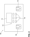
- FIG. 2 illustrates a front view of one embodiment of the charging station 106 in accordance with aspects of the present subject matter.
- the charging station 106 includes an electric charging port 108.
- the electric charging port 108 is configured to receive electric power from a power source (e.g., the electric power grid, an electric generator, a mobile battery pack, etc.).
- the electric charging port 108 forms part of a mechanical interface that allows the electric work vehicle 10 to receive electric power from the power source.
- the electric charging port 108 is configured as a male or female electrical receptacle provided on the electric work vehicle 10.
- the electric charging port 108 may be configured as any other suitable device for coupling a power source, such as an electric power cord or cable extending outward from the electric work vehicle 10.
- the charging station 106 includes an electric outlet 110.
- the electric outlet 110 is configured to provide electric power to one or more remote devices (e.g., a power tool(s) being used at the work site along with the electric work vehicle 10).
- the electric outlet 110 forms part of a mechanical interface that allows the electric work vehicle 10 to provide or transmit electric power to the remote device(s).
- the electric outlet 110 is configured as a male or female electrical receptacle provided on the electric work vehicle 10.
- the electric outlet 110 may be configured as any other suitable device for coupling a remote device, such as an electric power cord or cable extending outward from the electric work vehicle 10.
- the charging station 106 of the electric work vehicle 10 may have any suitable number of electric charging ports 108.
- the charging station 106 may include multiple electric charging ports 108 to allow the electric work vehicle 10 to receive electric power from multiple power sources, if available.
- the charging station 106 of the electric work vehicle 10 may have any suitable number of electric outlets 110.
- the charging station 106 may include multiple electric outlets 110 to allow the electric work vehicle 10 to charge or power multiple remote devices.
- the charging station 106 may include a user interface 112. More specifically, the user interface 112 may be configured to receive inputs (e.g., inputs associated with the charging capacity of the power source) from the operator. As such, the user interface 112 may include one or more input devices 116, such as touchscreens, keypads, touchpads, knobs, buttons, sliders, switches, mice, microphones, and/or the like, which are configured to receive inputs from the operator. As will be described below, such inputs may, in turn, be transmitted to a computing system for use in controlling the operation of the electric work vehicle 10 and/or the associated charging system.
- inputs e.g., inputs associated with the charging capacity of the power source
- the user interface 112 may include one or more input devices 116, such as touchscreens, keypads, touchpads, knobs, buttons, sliders, switches, mice, microphones, and/or the like, which are configured to receive inputs from the operator.
- inputs may, in turn, be transmitted to a computing system for
- the user interface 112 may include one or more feedback devices 114, such as display screens, speakers, warning lights, and/or the like, which are configured to provide feedback from the computing system to the operator (e.g., feedback associated with the charging capacity of the power source and/or the power draw from the remote device(s)).
- the user interface 112 may be positioned at a separate location from the charging station 106, such as within the cab 28 of the electric work vehicle 10.
- the configuration of the electric work vehicle 10 described above and shown in FIGS. 1 and 2 is provided only to place the present subject matter in an exemplary field of use. Thus, the present subject matter may be readily adaptable to any manner of electric vehicle configuration.
- FIG. 3 a schematic view of one embodiment of a system 100 for charging an electric work vehicle is illustrated in accordance with aspects of the present subject matter.
- the system 100 will be described herein with reference to the electric work vehicle 10 described above with reference to FIGS. 1 and 2 .
- the disclosed system 100 may generally be utilized with electric work vehicles having any other suitable vehicle configuration.
- the electric charging port 108 is electrically coupled to the energy storage device(s) 104 of the electric work vehicle 10.
- the electric charging port 108 is electrically coupled to the energy storage device(s) 104 via electrical connections 124, 126, 128.
- the electric charging port 108 is electrically coupled to a power source 118 via a power cord or cable 120.
- the electric charging port 108 may receive electric power received from the power source 118 via the power cable 120. The received electric power may then be transmitted to the energy storage device(s) 104 via the electrical connections 124, 126, 128.
- Electric power from the energy storage device(s) 104 may then be transmitted to the electric motor(s) 102 via an electric connection 130.
- the electric charging port 108 and the energy storage device(s) 104 may be electrically coupled in any other suitable manner.
- the power source 118 may correspond to any suitable source of electric power.
- the power source 118 may correspond to the electric power grid, an electric generator (e.g., powered by an internal combustion engine), a battery cart, and/or the like.
- the electric charging port 108 is electrically coupled to the electric outlet 110 of the electric work vehicle 10.
- the electric charging port 108 is electrically coupled to the energy electric outlet 110 via electrical connections 124, 126, 132, 134.
- the electric outlet 110 is electrically coupled to a remote device 136 via a power cord or cable 138.
- electric power received by the electric charging port 108 may then be transmitted to the electric outlet 119 via the electrical connections 124, 126, 132, 134.
- the electric power received by the electric outlet 110 may, in turn, be transmitted to the remote device 135 via the power cable 138.
- the electric charging port 108 and the energy storage device(s) 104 may be electrically coupled in any other suitable manner.
- the remote device 136 may correspond to any suitable electrically power device that is separate from or otherwise remote from the electric work vehicle 10.
- the remote device 136 may correspond to a power tool (e.g., a drill, saw, etc.), an electronic computing device (e.g., a laptop, Smartphone, tablet, etc.), and/or the like.
- a power tool e.g., a drill, saw, etc.
- an electronic computing device e.g., a laptop, Smartphone, tablet, etc.
- any suitable number of remote devices 136 may be electrically coupled to the system 100, such as when the electric work vehicle 10 includes multiple electric outlets 110.
- the system 100 includes one or more power flow control devices 122.
- the power flow control device(s) 122 is configured to control the flow or distribution of the electric power received by the electric charging port 108 between the energy storage device(s) 104 and the electric outlet 110.
- the power flow control device(s) 122 is electrically coupled to the electric charging port 108 via the electrical connections 120, 124, 126.
- the power flow control device(s) 122 is electrically coupled to the energy storage device(s) 104 via the electrical connection 128.
- the power flow control device(s) 122 is electrically coupled to the electric outlet 110 via the electrical connections 132, 134.
- the power flow control device(s) 122, the energy storage device(s) 104, and the electric outlet 110 may be electrically coupled in any other suitable manner.
- the power flow control device(s) 122 may direct all or a portion of the electric power received by the electric charging port 108 to the energy storage device(s) 104 and/or all or a portion of the electric power received by the electric charging port 108 to the electric outlet 110.
- the power flow control device(s) 122 may be configured as any suitable device or combination of devices to control the flow of electric power between the energy storage device(s) 104 and the electric outlet 110.
- the power flow control device(s) 122 may correspond to any combination and/or number of switches, relays, transistors, and/or the like.
- the various electric connections 124, 126, 128, 132, 134 may be configured as any suitable type(s) of device(s) configured to transmit electric power between components.
- the electric connections 124, 126, 128, 132, 134 may be configured as electric wires, cables, bus bars, and/or the like.
- the system 100 may include a charging capacity sensor 140.
- the charging capacity sensor 140 is configured to generate data indicative of the charging capacity of the electric power received by the electric charging port 108.
- the charging capacity sensor 140 may be electrically coupled between the electric charging port 108 and the power flow control device(s) 122.
- the data generated by the charging capacity sensor 140 may be used to control the distribution the electric power received by the electric charging port 108 between the energy storage device(s) 104 and the electric outlet 110.
- the charging capacity sensor 140 may be configured as any suitable type of sensing device(s) configured to generate data indicative of the charging capacity of the received electric power, such as an ammeter, a power consumption sensor, and/or the like.
- the charging capacity of the electric power received by the electric charging port 108 may correspond to any suitable parameter indicative of the ability of the received electric power to charge and/or power an electric device.
- the charging capacity of the received electric power may be the current (e.g., amperage) of the electric power, the power/energy per unit time (e.g., wattage) of the electric power, and/or the like.
- the system 100 may include a power draw sensor 142.
- the power draw sensor 142 is configured to generate data indicative of the power draw from the remote device 136.
- the power draw sensor 142 may be electrically coupled between the power flow control device(s) 122 and the electric outlet 110.
- the data generated by the power draw sensor 142 may be used to control the distribution the electric power received by the electric charging port 108 between the energy storage device(s) 104 and the electric outlet 110.
- the power draw sensor 142 may be configured as any suitable type of sensing device(s) configured to generate data indicative of the power draw of the remote device 136, such as an ammeter, a power consumption sensor, and/or the like.
- the power draw of the remote device 136 may correspond to any suitable parameter indicative of the amount of power drawn or being consumed by the remote 136.
- the power draw of the remote device 136 may be the current (e.g., amperage) being pulled by the remote device 136, the power/energy per unit time (e.g., wattage) being consumed by the remote device 136, and/or the like.
- the system 100 includes a computing system 144 communicatively coupled to one or more components of the electric work vehicle 10 and/or the system 100 to allow the operation of such components to be electronically or automatically controlled by the computing system 144.
- the computing system 144 may be communicatively coupled to the charging capacity sensor 140 via a communicative link 146.
- the computing system 144 may be configured to receive data from the charging capacity sensor 140 that is indicative of the charging capacity of the electric power being received by the electric charging port 108.
- the computing system 144 may be communicatively coupled to the power draw sensor 142 via the communicative link 146.
- the computing system 144 may be configured to receive data from the power draw sensor 142 that is indicative of the power draw from the remote device 136. Furthermore, the computing system 144 may be communicatively coupled to the power flow control device(s) 122 via the communicative link 146. As such, the computing system 144 may be configured to control the operation of the power flow control device(s) 122 to control the distribution of electric power between the energy storage device(s) 104 and the electric outlet 110. In addition, the computing system 144 may be communicatively coupled to the user interface 112 via the communicative link 146. As such, the computing system 144 may be configured to receive operator inputs from the user interface 112. Additionally, the computing system 144 may be communicatively coupled to any other suitable components of the electric work vehicle 10 and/or the system 100.
- the computing system 144 may comprise one or more processor-based devices, such as a given controller or computing device or any suitable combination of controllers or computing devices.
- the computing system 144 may include one or more processor(s) 148 and associated memory device(s) 150 configured to perform a variety of computer-implemented functions.
- processor refers not only to integrated circuits referred to in the art as being included in a computer, but also refers to a controller, a microcontroller, a microcomputer, a programmable logic circuit (PLC), an application specific integrated circuit, and other programmable circuits.
- the memory device(s) 150 of the computing system 144 may generally comprise memory element(s) including, but not limited to, a computer readable medium (e.g., random access memory RAM)), a computer readable non-volatile medium (e.g., a flash memory), a floppy disk, a compact disk-read only memory (CD-ROM), a magneto-optical disk (MOD), a digital versatile disk (DVD) and/or other suitable memory elements.
- Such memory device(s) 150 may generally be configured to store suitable computer-readable instructions that, when implemented by the processor(s) 148, configure the computing system 144 to perform various computer-implemented functions, such as one or more aspects of the methods and algorithms that will be described herein.
- the computing system 144 may also include various other suitable components, such as a communications circuit or module, one or more input/output channels, a data/control bus and/or the like.
- the various functions of the computing system 144 may be performed by a single processor-based device or may be distributed across any number of processor-based devices, in which instance such devices may be considered to form part of the computing system 144.
- the functions of the computing system 144 may be distributed across multiple application-specific controllers or computing devices, such as a navigation controller, an engine controller, a transmission controller, an implement controller, and/or the like.
- control logic 200 that may be executed by the computing system 144 (or any other suitable computing system) for charging an electric work vehicle is illustrated in accordance with aspects of the present subject matter.
- the control logic 200 shown in FIG. 4 is representative of steps of one embodiment of an algorithm that can be executed to charge an electric work vehicle and one or more remote devices in a manner that allows for a single power source to charge multiple electrically powered devices in a minimum amount of time.
- the control logic 200 may be advantageously utilized in association with a charging system installed on or forming part of an electric work vehicle to allow for real-time control of vehicle and remote device electric charging without requiring substantial computing resources and/or processing time.
- the control logic 200 may be used in association with any other suitable system, application, and/or the like for charging an electric work vehicle.
- the control logic 200 includes determining the charging capacity of an energy storage device of an electric work vehicle.
- the computing system 144 may be configured to determine the charging capacity of the energy storage device(s) 104 of the electric work vehicle 10. For example, in one embodiment, the computing system 144 may access the charging capacity of the energy storage device(s) 104 from its memory device(s) 150. In another embodiment, the operator of the electric work vehicle 10 may provide the charging capacity of the energy storage device(s) 104 via the user interface 112. However, in alternative embodiments, the computing system 144 may be configured to determine the charging capacity of the energy storage device(s) 104 in any other suitable manner, such as via suitable sensor data.
- the charging capacity of the energy storage device(s) 104 may correspond to any suitable parameter indicative of amount or nature of the electric power that the energy storage device(s) 104 can accept and store.
- the charging capacity of the energy storage device(s) 104 may be the current (e.g., amperage) of the electric power that can be accepted by the energy storage device(s) 104 during charging, the power/energy per unit time (e.g., wattage) of the electric power that can be accepted by the energy storage device(s) 104 during charging, and/or the like.
- the control logic 200 includes receiving sensor data indicative of the charging capacity of the electric power received by an electric charging port of the electric work vehicle.
- the computing system 144 may be communicatively coupled to the charging capacity sensor 140 via the communicative link 146.
- the computing system 144 may receive data from the charging capacity sensor 140. Such data may, in turn, be indicative of the charging capacity of the electric power received by the electric charging port 108 from the power source 118.
- the control logic 200 includes determining the charging capacity of the electric power received by the electric charging port of the electric work vehicle.
- the computing system 144 may be configured to analyze the sensor data received at (204) to determine the charging capacity of the electric power received by the electric charging port 108 from the power source 118.
- the charging capacity of the electric power received by the electric charging port 108 may be determined based on an operator input received from the user interface 112.
- the computing system 144 is configured to control the distribution the electric power received by the electric charging port 108 between the energy storage device(s) 104 and the electric outlet 110 based on the determined the charging capacity of the electric power received by the electric charging port 108 and the charging capacity of the energy storage device(s) 104.
- the control logic 200 includes determining whether a remote device is electrically coupled to an electric outlet of the electric work vehicle.
- the computing system 144 may be configured to determining when the remote device 136 is electrically coupled to the electric outlet 110 of the electric work vehicle 10.
- the computing system 144 may determine when the remote device 136 is electrically coupled to the electric outlet 110 based on sensor data that is indicative the presence or lack of an electric load on the electric outlet 110, sensor data that is indicative a mechanical connection between the electric outlet 110 and the remote device 136, and/or the like.
- the control logic 200 proceeds to (210).
- the electric power received by the electric charging port 108 is used to charge the energy storage device(s) 104.
- the control logic 200 proceeds to (212).
- the charging/powering of the remote device 136 is prioritized over the charging the energy storage device(s) 104.
- the control logic 200 includes initiating the supply of electric power from the electric charging port to the energy storage device of the electric work vehicle.
- the computing system 144 may be configured to initiate the supply of electric power from the electric charging port 108 to the energy storage device(s) 104. Specifically, the computing system 144 may initiate the supply of electric power from the electric charging port 108 to the energy storage device(s) 104 in an amount equal to the lesser of the charging capacity of the energy storage device(s) 104 determined at (202) or the charging capacity of the electric power received by the electric charging port 108 determined at (206).
- the computing system 144 may transmit control signals to the power flow control device(s) 122.
- control signals instruct the power flow control device(s) 122 to direct electric power from the electric charging port 108 to the energy storage device(s) 104 in the selected amount.
- the energy storage device(s) 104 of the electric work vehicle 10 is charged at the maximum rate permitted by the charging capacities of the energy storage device(s) 104 and the electric power received by the electric charging port 108.
- the charging capacity of the energy storage device(s) 104 is sixty amps and the charging capacity of the electric power received by the electric charging port 108 is fifty amps, all fifty amps of electric power received by the electric charging port 108 is supplied to the energy storage device(s) 104 for charging.
- the control logic 200 includes receiving sensor data indicative of the power draw from the remote device.
- the computing system 144 may be communicatively coupled to the power draw sensor 142 via the communicative link 146.
- the computing system 144 may receive data from the power draw sensor 142. Such data may, in turn, be indicative of the power draw of the remote device 136.
- the control logic 200 includes determining the power draw from the remote device.
- the computing system 144 may be configured to analyze the power draw sensor data received at (212) to determine the power draw from the remote device 136.
- the power draw from the remote device136 may be used to in addition to the charging capacities of the energy storage device(s) 104 and the electric power received from the electric charging port 108 to control the distribution the electric power received by the electric charging port 108 between the energy storage device(s) 104 and the electric outlet 110.
- the control logic 200 includes determining whether the charging capacity of the electric power received by the electric charging port is greater than the power draw of the remote device.
- the computing system 144 may be configured to compare the charging capacity of the electric power received by the electric charging port 108 determined at (206) and the power draw from the remote device 136 determined at (214). When the charging capacity of the electric power received by the electric charging port 108 exceeds the power draw of the remote device 136, the control logic 200 proceeds to (218). Conversely, when the charging capacity of the electric power received by the electric charging port 108 does not exceed the power draw of the remote device 136, the control logic 200 proceeds to (222).
- the control logic 200 includes initiating the supply of a first portion of the electric power from the electric charging port to the electric outlet of the electric work vehicle.
- the computing system 144 may be configured to initiate the supply of a first portion of the electric power from the electric charging port 108 to the electric outlet 110.
- the first portion of the electric power from the electric charging port 108 is supplied to the electric outlet 110 in an amount equal to the power draw from the remote device 136 determined at (214).
- the computing system 144 may transmit control signals to the power flow control device(s) 122.
- Such control signals instruct the power flow control device(s) 122 to direct electric power from the electric charging port 108 to the electric outlet 110 in the selected amount.
- the control logic 200 includes initiating the supply of a second portion of the electric power from the electric charging port to the energy storage device of the electric work vehicle.
- the computing system 144 may be configured to initiate the supply of a second portion of the electric power from the electric charging port 108 to the energy storage device(s) 104.
- the second portion of the electric power from the electric charging port 108 is supplied to the electric outlet 110 in an amount equal to the difference between the charging capacity of the electric power received by the electric charging port 108 determined at (206) and the power draw from the remote device 136 determined at (214).
- the computing system 144 may transmit control signals to the power flow control device(s) 122.
- Such control signals instruct the power flow control device(s) 122 to direct electric power from the electric charging port 108 to the energy storage device(s) 104 in the selected amount.
- the control logic 200 Upon completion of (220), the control logic 200 returns to (202).
- the control logic 200 includes initiating the supply of electric power from the electric charging port to the electric outlet of the electric work vehicle.
- the computing system 144 may be configured to initiate the supply of electric power from the electric charging port 108 to the electric outlet 110. Specifically, the computing system 144 may initiate the supply of electric power from the electric charging port 108 to the energy storage device(s) 104 in an amount equal to the lesser of the charging capacity of the electric power received by the electric charging port 108 determined at (206) or the power draw from the remote device 136 determined at (214).
- the computing system 144 may transmit control signals to the power flow control device(s) 122.
- control signals instruct the power flow control device(s) 122 to direct electric power from the electric charging port 108 to the electric outlet in the selected amount.
- the charging/powering of the remote device 136 is prioritized over the charging of the energy storage device(s) 104 of the electric work vehicle 10. For example, when the charging capacity of the electric power received by the electric charging port 108 is sixty amps and the power draw of the remote device 136 is fifty amps, only fifty amps of the electric power received by the electric charging port 108 is supplied to the electric outlet 110 for use by the remote device 136. The remaining ten amps of the electric power received by the electric charging port 108 are supplied to the energy storage device(s) 104 for charging.
- the charging capacity of the electric power received by the electric charging port 108 is fifty amps and the power draw of the remote device 136 is sixty amps, all fifty amps of the electric power received by the electric charging port 108 is supplied to the electric outlet 110 for use by the remote device 136.
- the energy storage device(s) 104 may be configured to condition the electric power supplied to the electric outlet 110. Specifically, in such instances, even though the charging/operation of the remote device 136 is being prioritized over the charging of the energy storage device(s) 104, the electric power received from the power source 118 may initially be supplied to the energy storage device(s) 108. The energy storage device(s) 108 may, in turn, condition the received electric power before supplying the conditioned electric power to the electric outlet 110 in the amount described above for use by the remote device 136.
- the energy storage device(s) 104 may adjust the voltage of the electric power received by the electric charging port 108 to the appropriate voltage for the remote device 136 (e.g., bump the voltage up to 120 volts).
- the energy storage device(s) 104 may adjust the frequency of the electric power received by the electric charging port 108 to the appropriate frequency for the remote device 136 (e.g., to adjust the frequency to sixty Hertz).
- the energy storage device(s) 104 may adjust any other suitable parameter(s) of the electric power received by the electric charging port 108 to condition or otherwise clean up the received electric power for eventual use by the remote device 136.
- the electric power received by the electric charging port 108 may be supplied directly to the electric outlet 110 in such instances.
- the control logic 200 includes initiating the supply of additional electric power from the energy storage device of the electric work vehicle to the electric outlet of the electric work vehicle.
- the computing system 144 may be configured to initiate the supply of additional electric power from the energy storage device(s) 104 to the electric outlet 110.
- the computing system 144 may initiate the supply of additional electric power from the energy storage device(s) 104 to the electric outlet 110 in an amount equal the difference between the power draw from the remote device 136 determined at (214) and the charging capacity of the electric power received by the electric charging port 108 determined at (206).
- the computing system 144 may transmit control signals to the power flow control device(s) 122.
- control signals instruct the power flow control device(s) 122 to direct electric power from the energy storage device(s) 104 to the electric outlet 110 in the selected amount.
- Such additional electric power from the energy storage device(s) 104 supplements the electric power received from the electric charging port 108 to provide sufficient electric power to the electric outlet 110 to accommodate the full power draw from the remote device 136.
- the control logic 200 Upon completion of (224), the control logic 200 returns to (202).
- FIG. 5 a flow diagram of one embodiment of a method 300 for charging an electric work vehicle is illustrated in accordance with aspects of the present subject matter.
- the method 300 will be described herein with reference to the electric work vehicle 10 and the system 100 described above with reference to FIGS. 1-4 .
- the disclosed method 300 may generally be implemented with any electric work vehicle having any suitable vehicle configuration and/or within any system having any suitable system configuration.
- FIG. 5 depicts steps performed in a particular order for purposes of illustration and discussion, the methods discussed herein are not limited to any particular order or arrangement.
- steps of the methods disclosed herein can be omitted, rearranged, combined, and/or adapted in various ways without deviating from the scope of the present disclosure.
- the method 300 includes determining, with a computing system, the charging capacity of an energy storage device of an electric work vehicle.
- the computing system 144 may determine the charging capacity of the energy storage device(s) 104 of the electric work vehicle 10.
- the method 300 includes determining, with the computing system, the charging capacity of electric power received by an electric charging port on the electric work vehicle.
- the computing system 144 may determine the charging capacity of the electric power received by the electric charging port 108 on the electric work vehicle 10, such as from data received from the charging capacity sensor 140 or an operator input provided to the user interface 112.
- the method 300 includes controlling, with the computing system, the distribution of the electric power received by the electric charging port between the energy storage device and an electric outlet based on at least one of the determined charging capacity of the energy storage device or the determined charging capacity of the electric power received by an electric charging port.
- the computing system 144 may control the operation of the power flow control device(s) 122 to control the distribution of the electric power received by the electric charging port 108 between the energy storage device(s) 104 and the electric outlet 110 based on the determined charging capacity of the energy storage device(s) 104 and/or the determined charging capacity of the electric power received by an electric charging port 108.
- the steps of the control logic 200 and the method 300 are performed by the computing system 144 upon loading and executing software code or instructions which are tangibly stored on a tangible computer readable medium, such as on a magnetic medium, e.g., a computer hard drive, an optical medium, e.g., an optical disc, solid-state memory, e.g., flash memory, or other storage media known in the art.
- a tangible computer readable medium such as on a magnetic medium, e.g., a computer hard drive, an optical medium, e.g., an optical disc, solid-state memory, e.g., flash memory, or other storage media known in the art.
- any of the functionality performed by the computing system 144 described herein, such as the control logic 200 and the method 300 is implemented in software code or instructions which are tangibly stored on a tangible computer readable medium.
- the computing system 144 loads the software code or instructions via a direct interface with the computer readable medium or via a wired and/or wireless network.
Landscapes
- Engineering & Computer Science (AREA)
- Power Engineering (AREA)
- Transportation (AREA)
- Mechanical Engineering (AREA)
- Life Sciences & Earth Sciences (AREA)
- Sustainable Development (AREA)
- Sustainable Energy (AREA)
- Charge And Discharge Circuits For Batteries Or The Like (AREA)
Applications Claiming Priority (1)
| Application Number | Priority Date | Filing Date | Title |
|---|---|---|---|
| US202263402491P | 2022-08-31 | 2022-08-31 |
Publications (1)
| Publication Number | Publication Date |
|---|---|
| EP4331889A1 true EP4331889A1 (de) | 2024-03-06 |
Family
ID=87863490
Family Applications (1)
| Application Number | Title | Priority Date | Filing Date |
|---|---|---|---|
| EP23194375.4A Pending EP4331889A1 (de) | 2022-08-31 | 2023-08-30 | Ladesystem für ein elektrisches arbeitsfahrzeug und zugehöriges verfahren |
Country Status (2)
| Country | Link |
|---|---|
| US (1) | US20240066991A1 (de) |
| EP (1) | EP4331889A1 (de) |
Families Citing this family (1)
| Publication number | Priority date | Publication date | Assignee | Title |
|---|---|---|---|---|
| WO2026010543A1 (en) * | 2024-07-04 | 2026-01-08 | Husqvarna Ab | Electrical energy storage devices for floor saws and other types of construction equipment |
Citations (3)
| Publication number | Priority date | Publication date | Assignee | Title |
|---|---|---|---|---|
| EP2597005A2 (de) * | 2011-11-22 | 2013-05-29 | Mitsubishi Jidosha Kogyo Kabushiki Kaisha | Stromversorgungsfahrzeug |
| WO2013179312A2 (en) * | 2012-06-01 | 2013-12-05 | Mahindra & Mahindra Ltd. | Multi-powered electric vehicle |
| EP2800227A1 (de) * | 2011-12-31 | 2014-11-05 | Shenzhen BYD Auto R&D Company Limited | Elektrisches automobil und entladungsvorrichtung dafür |
Family Cites Families (11)
| Publication number | Priority date | Publication date | Assignee | Title |
|---|---|---|---|---|
| JPH11343642A (ja) * | 1998-06-01 | 1999-12-14 | Kobe Steel Ltd | バッテリー駆動式作業機械 |
| JP4542819B2 (ja) * | 2004-05-21 | 2010-09-15 | 株式会社小松製作所 | 油圧機械、油圧機械の健康状態を監視するためのシステム及び方法 |
| US8807635B2 (en) * | 2011-02-11 | 2014-08-19 | Cnh Industrial America Llc | Self-cleaning cab floor |
| US10207754B2 (en) * | 2017-03-06 | 2019-02-19 | Cnh Industrial America Llc | Track system for a work vehicle |
| JP6944426B2 (ja) * | 2018-09-05 | 2021-10-06 | 株式会社日立建機ティエラ | 電動式建設機械 |
| US10800279B2 (en) * | 2018-09-13 | 2020-10-13 | Ford Global Technologies, Llc | Portable charging system and charging method |
| EP4045347A1 (de) * | 2019-10-14 | 2022-08-24 | Textron, Inc. | Elektrischer pushback-schlepper |
| EP4313668A1 (de) * | 2021-04-01 | 2024-02-07 | Veturex Inc. | Steckmodul zum drahtlosen laden |
| US12194827B2 (en) * | 2022-07-07 | 2025-01-14 | GM Global Technology Operations LLC | Integrated electrified propulsion system for a vehicle |
| EP4580905A1 (de) * | 2022-08-30 | 2025-07-09 | Atieva, Inc. | Ladezustandsausgleich in einem geteilten batteriesystem |
| US20240075826A1 (en) * | 2022-09-06 | 2024-03-07 | GM Global Technology Operations LLC | Charging connector |
-
2023
- 2023-08-29 US US18/457,715 patent/US20240066991A1/en active Pending
- 2023-08-30 EP EP23194375.4A patent/EP4331889A1/de active Pending
Patent Citations (3)
| Publication number | Priority date | Publication date | Assignee | Title |
|---|---|---|---|---|
| EP2597005A2 (de) * | 2011-11-22 | 2013-05-29 | Mitsubishi Jidosha Kogyo Kabushiki Kaisha | Stromversorgungsfahrzeug |
| EP2800227A1 (de) * | 2011-12-31 | 2014-11-05 | Shenzhen BYD Auto R&D Company Limited | Elektrisches automobil und entladungsvorrichtung dafür |
| WO2013179312A2 (en) * | 2012-06-01 | 2013-12-05 | Mahindra & Mahindra Ltd. | Multi-powered electric vehicle |
Also Published As
| Publication number | Publication date |
|---|---|
| US20240066991A1 (en) | 2024-02-29 |
Similar Documents
| Publication | Publication Date | Title |
|---|---|---|
| US12291836B2 (en) | Electrically powered construction machine | |
| EP2918435B1 (de) | Nutzfahrzeug | |
| CN112004973A (zh) | 电动式作业机械 | |
| US20210316713A1 (en) | System and method for runtime planning of an electric battery powered work vehicle | |
| US8589037B2 (en) | Electric drive control for a machine | |
| CN101528500A (zh) | 多用途移动发电机械 | |
| US20240227624A1 (en) | Method to control multiple parallel battery packs | |
| US20240332970A1 (en) | Systems and methods for managing electrical power in a worksite | |
| KR20240119212A (ko) | 전력식 동력기계의 제어 시스템 및 방법 | |
| EP4331889A1 (de) | Ladesystem für ein elektrisches arbeitsfahrzeug und zugehöriges verfahren | |
| US20240125093A1 (en) | Electric Work Machine | |
| US20250289338A1 (en) | System and method for charging electric construction vehicles | |
| US20260027933A1 (en) | Apparatus for charging battery for construction machine, and charging method using same | |
| JP2008069516A (ja) | 電動式建設機械 | |
| JP2011103720A (ja) | 油圧ユニットの電源システム | |
| EP4111002B1 (de) | System und verfahren zur steuerung des pumpenbetriebsgeschwindigkeitsbereichs eines elektrischen arbeitsfahrzeugs auf der basis von hydraulikflüssigkeitsdruck | |
| US12466280B2 (en) | Working machine | |
| WO2024155404A1 (en) | Removable system pack for electric work machine | |
| US20240157809A1 (en) | Systems and methods for a hydraulic system | |
| US20250109572A1 (en) | Hot swappable battery configuration | |
| KR20160133145A (ko) | 작업기계의 충전 시스템 및 충전 방법 | |
| US20250128643A1 (en) | Self-contained power unit for a work machine | |
| US20250357750A1 (en) | Contactor selection to open under load | |
| US20240424935A1 (en) | Charging system for electric work vehicles and associated methods | |
| US20250376062A1 (en) | Modular dispenser |
Legal Events
| Date | Code | Title | Description |
|---|---|---|---|
| PUAI | Public reference made under article 153(3) epc to a published international application that has entered the european phase |
Free format text: ORIGINAL CODE: 0009012 |
|
| STAA | Information on the status of an ep patent application or granted ep patent |
Free format text: STATUS: THE APPLICATION HAS BEEN PUBLISHED |
|
| AK | Designated contracting states |
Kind code of ref document: A1 Designated state(s): AL AT BE BG CH CY CZ DE DK EE ES FI FR GB GR HR HU IE IS IT LI LT LU LV MC ME MK MT NL NO PL PT RO RS SE SI SK SM TR |
|
| STAA | Information on the status of an ep patent application or granted ep patent |
Free format text: STATUS: REQUEST FOR EXAMINATION WAS MADE |
|
| 17P | Request for examination filed |
Effective date: 20240906 |
|
| RBV | Designated contracting states (corrected) |
Designated state(s): AL AT BE BG CH CY CZ DE DK EE ES FI FR GB GR HR HU IE IS IT LI LT LU LV MC ME MK MT NL NO PL PT RO RS SE SI SK SM TR |