EP4332007A1 - Antriebsanordnung - Google Patents
Antriebsanordnung Download PDFInfo
- Publication number
- EP4332007A1 EP4332007A1 EP23185764.0A EP23185764A EP4332007A1 EP 4332007 A1 EP4332007 A1 EP 4332007A1 EP 23185764 A EP23185764 A EP 23185764A EP 4332007 A1 EP4332007 A1 EP 4332007A1
- Authority
- EP
- European Patent Office
- Prior art keywords
- tape
- bracket
- wheel
- tool
- motor
- Prior art date
- Legal status (The legal status is an assumption and is not a legal conclusion. Google has not performed a legal analysis and makes no representation as to the accuracy of the status listed.)
- Withdrawn
Links
- 230000006835 compression Effects 0.000 claims description 19
- 238000007906 compression Methods 0.000 claims description 19
- 239000000463 material Substances 0.000 description 5
- 238000005096 rolling process Methods 0.000 description 2
- 238000003466 welding Methods 0.000 description 2
- 239000004035 construction material Substances 0.000 description 1
Images



Classifications
-
- B—PERFORMING OPERATIONS; TRANSPORTING
- B65—CONVEYING; PACKING; STORING; HANDLING THIN OR FILAMENTARY MATERIAL
- B65B—MACHINES, APPARATUS OR DEVICES FOR, OR METHODS OF, PACKAGING ARTICLES OR MATERIALS; UNPACKING
- B65B13/00—Bundling articles
- B65B13/02—Applying and securing binding material around articles or groups of articles, e.g. using strings, wires, strips, bands or tapes
- B65B13/04—Applying and securing binding material around articles or groups of articles, e.g. using strings, wires, strips, bands or tapes with means for guiding the binding material around the articles prior to severing from supply
- B65B13/14—Pairs of carriers or guides movable around opposite sides of the articles
-
- B—PERFORMING OPERATIONS; TRANSPORTING
- B65—CONVEYING; PACKING; STORING; HANDLING THIN OR FILAMENTARY MATERIAL
- B65B—MACHINES, APPARATUS OR DEVICES FOR, OR METHODS OF, PACKAGING ARTICLES OR MATERIALS; UNPACKING
- B65B13/00—Bundling articles
- B65B13/18—Details of, or auxiliary devices used in, bundling machines or bundling tools
- B65B13/22—Means for controlling tension of binding means
-
- B—PERFORMING OPERATIONS; TRANSPORTING
- B65—CONVEYING; PACKING; STORING; HANDLING THIN OR FILAMENTARY MATERIAL
- B65B—MACHINES, APPARATUS OR DEVICES FOR, OR METHODS OF, PACKAGING ARTICLES OR MATERIALS; UNPACKING
- B65B13/00—Bundling articles
- B65B13/02—Applying and securing binding material around articles or groups of articles, e.g. using strings, wires, strips, bands or tapes
- B65B13/025—Hand-held tools
-
- B—PERFORMING OPERATIONS; TRANSPORTING
- B65—CONVEYING; PACKING; STORING; HANDLING THIN OR FILAMENTARY MATERIAL
- B65B—MACHINES, APPARATUS OR DEVICES FOR, OR METHODS OF, PACKAGING ARTICLES OR MATERIALS; UNPACKING
- B65B13/00—Bundling articles
- B65B13/02—Applying and securing binding material around articles or groups of articles, e.g. using strings, wires, strips, bands or tapes
- B65B13/04—Applying and securing binding material around articles or groups of articles, e.g. using strings, wires, strips, bands or tapes with means for guiding the binding material around the articles prior to severing from supply
- B65B13/08—Single guide or carrier for the free end of material movable part-away around articles from one side only
-
- B—PERFORMING OPERATIONS; TRANSPORTING
- B65—CONVEYING; PACKING; STORING; HANDLING THIN OR FILAMENTARY MATERIAL
- B65B—MACHINES, APPARATUS OR DEVICES FOR, OR METHODS OF, PACKAGING ARTICLES OR MATERIALS; UNPACKING
- B65B13/00—Bundling articles
- B65B13/18—Details of, or auxiliary devices used in, bundling machines or bundling tools
- B65B13/185—Details of tools
- B65B13/187—Motor means
-
- B—PERFORMING OPERATIONS; TRANSPORTING
- B65—CONVEYING; PACKING; STORING; HANDLING THIN OR FILAMENTARY MATERIAL
- B65B—MACHINES, APPARATUS OR DEVICES FOR, OR METHODS OF, PACKAGING ARTICLES OR MATERIALS; UNPACKING
- B65B13/00—Bundling articles
- B65B13/18—Details of, or auxiliary devices used in, bundling machines or bundling tools
- B65B13/24—Securing ends of binding material
- B65B13/32—Securing ends of binding material by welding, soldering, or heat-sealing; by applying adhesive
-
- B—PERFORMING OPERATIONS; TRANSPORTING
- B65—CONVEYING; PACKING; STORING; HANDLING THIN OR FILAMENTARY MATERIAL
- B65B—MACHINES, APPARATUS OR DEVICES FOR, OR METHODS OF, PACKAGING ARTICLES OR MATERIALS; UNPACKING
- B65B13/00—Bundling articles
- B65B13/18—Details of, or auxiliary devices used in, bundling machines or bundling tools
- B65B13/24—Securing ends of binding material
- B65B13/32—Securing ends of binding material by welding, soldering, or heat-sealing; by applying adhesive
- B65B13/327—Hand tools
-
- B—PERFORMING OPERATIONS; TRANSPORTING
- B65—CONVEYING; PACKING; STORING; HANDLING THIN OR FILAMENTARY MATERIAL
- B65B—MACHINES, APPARATUS OR DEVICES FOR, OR METHODS OF, PACKAGING ARTICLES OR MATERIALS; UNPACKING
- B65B65/00—Details peculiar to packaging machines and not otherwise provided for; Arrangements of such details
- B65B65/02—Driving gear
Definitions
- the present disclosure relates to a tool for dispensing a weldable material about a bundle of elongate articles. More particularly, the present disclosure relates to a drive assembly for a tool for dispensing the weldable material about the bundle of elongate articles.
- a tool can be used for automatically bundling elongate articles such as wires, cables, or the like.
- a tool can feed a weldable tape about the bundled articles until the tape overlaps itself, tensioning the tape about the bundle of articles, and thereafter welding the tape at the location of the overlap to provide a tensioned loop which secures the bundle of articles.
- the tensioned loop can then be cut free from the remaining stock of tape so that the tool can be removed from the first bundle of articles and moved to a second location to secure a second portion of tape about a second bundle of articles.
- a drive apparatus for a tool to bundle a plurality of elongate articles using a weldable tape
- the drive apparatus having a first side and a second side and includes a guide block; a motor assembly including: a motor on the guide block at the first side, and a gear train in engagement with the motor and extending through the guide block; and a drive block on the guide block at the second side in engagement with the gear train, the drive block including: a first bracket, a second bracket, a first wheel assembly, a second wheel assembly, a channel extending through the drive block and configured to receive the weldable tape, and a spring element, wherein the spring element provides a compression force onto the first bracket and the second bracket; wherein the drive block engages the weldable tape at the channel based on the compression force to move the weldable tape through the tool.
- the apparatus further includes a controller, wherein the controller can control a motor torque of the motor to apply a desired tension to the weldable tape by the drive block.
- the apparatus further includes a motor block disposed on the first side of the guide block about the first worm gear, the second worm gear, the first gear train, and the second gear train.
- the first wheel assembly includes a first feed axle extending through the first bracket from the first side to the second side, a first wheel element fixedly disposed about the first feed axle in the first bracket, wherein the first wheel element extends into the channel and is configured to engage an upper surface of the weldable tape, and a first tape gear fixedly disposed about the first feed axle on the second side of the first bracket, wherein the first feed axle is configured to engage the drive axle, wherein the first feed axle rotates the first tape gear and the first wheel element in response to the rotation of the motor to feed the weldable tape through the tool.
- a surface of the first wheel element engaging the weldable tape is substantially smooth.
- a surface of the first wheel element engaging the weldable tape includes a ridged surface.
- the second wheel assembly includes a second feed axle extending through the second bracket from the first side to the second side, a second wheel element fixedly disposed about the first feed axle in the second bracket, wherein the second wheel element extends into the channel to engage a bottom surface of the weldable tape, and a second tape gear fixedly disposed about the first feed axle on the on the second side of the second bracket, wherein the second tape gear is configured to engage the first tape gear, wherein the second feed axle rotates the second wheel element in response to the rotation of the first tape gear to feed the weldable tape through the tool.
- a surface of the second wheel element engaging the weldable tape is substantially smooth.
- a surface of the second wheel element engaging the weldable tape includes a ridged surface.
- the drive block includes a gap between the first wheel assembly and the second wheel assembly in the channel.
- the drive block further includes a pin assembly laterally extending through the first bracket and the second bracket to allow the second bracket to pivotably move about the pin assembly relative to the first bracket, wherein the first wheel bracket and the second wheel bracket engage the weldable tape disposed in the channel of the drive block based on the compression force from the spring element.
- a tool for bundling a plurality of elongate articles using weldable tape having a first side and a second side and including a body, a handle, and a trigger
- the tool including a drive assembly in communicable connection with the trigger and including: a guide block, a motor assembly disposed on the guide block, the motor assembly including: a motor, and a gear train in engagement with a drive end of the motor and extending through the guide block; and a drive block opposite from the motor assembly on the guide block
- the drive block including: a first bracket, a second bracket, a first wheel assembly configured to engage the drive axle and rotate based on the rotation of the motor, a second wheel assembly configured to engage the first wheel assembly and rotate based on the rotation of the first wheel assembly, a channel extending through the drive block and configured to receive the weldable tape, and a spring element providing a compression force onto the first bracket and the second bracket, wherein the first wheel assembly and the second wheel assembly engage the weld
- the first wheel assembly includes a first feed axle extending through the first bracket from the first side to the second side, a first wheel element fixedly disposed about the first feed axle in the first bracket, wherein the first wheel element extends into the channel and is configured to engage an upper surface of the weldable tape, and a first tape gear fixedly disposed about the first feed axle on the second side of the first bracket, wherein the first feed axle is configured to engage the drive axle, wherein the first feed axle rotates the first tape gear and the first wheel element in response to the rotation of the motor to feed the weldable tape through the tool.
- a surface of the first wheel element engaging the weldable tape is substantially smooth.
- a surface of the first wheel element engaging the weldable tape includes a ridged surface.
- the second wheel assembly includes: a second feed axle extending through the second bracket from the first side to the second side, a second wheel element fixedly disposed about the first feed axle in the second bracket, wherein the second wheel element extends into the channel to engage a bottom surface of the weldable tape, and a second tape gear fixedly disposed about the first feed axle on the on the second side of the second bracket, wherein the second tape gear is configured to engage the first tape gear, wherein the second feed axle rotates the second wheel element in response to the rotation of the first tape gear to feed the weldable tape through the tool.
- a surface of the second wheel element engaging the weldable tape is substantially smooth.
- a surface of the second wheel element engaging the weldable tape includes a ridged surface.
- the drive block includes a gap between the first wheel assembly and the second wheel assembly at the channel.
- the drive block further includes a controller, wherein the controller can control a motor torque of the motor to apply a desired tension to the weldable tape by the drive block.
- FIG. 1 is a side view of the tool 100, according to some embodiments.
- the tool 100 can be referred to as an ultrasonic tying tool or the like.
- the tool 100 can bundle a plurality of elongate articles using weldable tape.
- the tool 100 includes a drive assembly 200 ( FIG. 2 ).
- the drive assembly 200 ( FIG. 2 ) can be centrally disposed in the tool 100.
- the drive assembly 200 can be disposed between a clamping assembly 400 and a cartridge assembly 500 of the tool 100.
- the weldable tape can be referred to as a strap, tie strap, plastic strap, tie wrap, tape, or the like.
- the tool 100 includes a housing 102 having a first side, a second side, a forward end, and a rear end.
- the housing 102 includes a body 104 and a handle 106.
- the handle 106 can include a trigger 108.
- the trigger 108 can be utilized by a user to operate the tool 100.
- the housing 102 is pistol-shaped. It is to be appreciated that other geometries for the housing are possible and that pistol-shaped is an example. Additional geometries are possible in accordance with the remaining disclosure.
- the tool 100 includes additional features for providing a tape material to the drive assembly 200 and to wrap the tape material around the plurality of elongate articles. However, unless specific reference is made otherwise, these additional components will not be discussed in additional detail.
- the tool 100 overcomes certain disadvantages associated with prior art tools in that the tool 100 is capable of securing a weldable tape about a bundle of elongate articles and thereafter welding and cutting the tape without loss of tension in the bundled articles and reducing friction forces. It is to be appreciated that the tool 100 includes additional features for bundling the tape material about the plurality of elongate articles. However, unless specific reference is made otherwise, these additional components will not be discussed in additional detail.
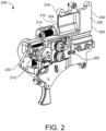
- FIG. 2 is a perspective view of a drive assembly 200, according to some embodiments.
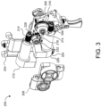
- FIG. 3 shows a partially exploded view of the drive assembly 200, according to some embodiments.
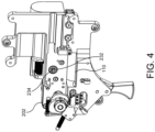
- FIG. 4 is a partially exposed perspective view of the drive assembly 200, according to some embodiments.
- FIG. 5 is a top view of the drive assembly 200, according to some embodiments.
- the tool 100 includes the drive assembly 200.
- the drive assembly 200 can be referred to as a drive apparatus or the like.
- the drive assembly 200 can include a guide block 202, a motor housing 208, a first motor assembly 204, and a drive block 206.
- the guide block 202 can be configured to mechanically couple to the clamping assembly 400.
- the guide block 202 can be configured to mechanically couple to the cartridge assembly 500 ( FIG. 1 ).
- the drive assembly 200 includes the guide block 202.
- the guide block 202 can be defined by a body and configured to receive the first motor assembly 204 and the drive block 206 onto the body.
- the guide block 202 can include any of a plurality of sizes and shapes to connect to the first motor assembly 204, the drive block 206, and other components of the drive assembly 200 and/or the tool 100.
- the geometry of the guide block 202 is shaped to conform to the housing 102 and/or to accommodate other components of the tool 100 including the first motor assembly 204 and the drive block 206. It is to be appreciated that other geometries for the guide block 202 are possible and that the illustrated shape is exemplary. Additional geometries are possible in accordance with the remaining disclosure.
- the drive assembly 200 includes the first motor assembly 204.
- the first motor assembly 204 can be configured to drive the drive block 206 to move the weldable tape through the drive assembly 200 and the tool 100.
- the first motor assembly 204 can cause a rotation of the drive block 206 in response to an operation of the trigger 108 by a user.
- the tool 100 can include a controller, the controller providing a control signal to the first motor assembly 204 to drive the drive block 206 and to move the weldable tape through the drive assembly 200 and the tool 100.
- the first motor assembly 204 can be detachably mounted to the guide block 202 on the first side 218.
- the first motor assembly 204 can be coupled to the guide block 202 with at least one fastener.
- the fastener can include, but is not limited to, screws, nuts, bolts, pins, rods, clamps, rivets, other fasteners, and any combination thereof.
- the drive assembly 200 includes the drive block 206 ( FIG. 2 ).
- the drive block 206 can be disposed in a receptacle 110 ( FIG. 4 ) on the second side of the guide block 202.
- the drive block 206 can be configured to apply a compression force onto the weldable tape and move the tape through the drive assembly 200 and the tool 100 in response to a rotation of the first motor assembly 204.
- the drive block 206 can be disposed on the second side 220 of the guide block 202.
- the drive block 206 can be coupled to the first motor assembly 204 through an aperture of the guide block 202.
- the first motor assembly 204 and the drive block 206 can be connected by a tab 234 ( FIG.
- the drive assembly 200 can include a second motor assembly 226.
- the drive assembly 200 can include a cam 210.
- the second motor assembly 226 can be disposed on the first side 218 of the guide block 202 proximal to the first motor assembly 204.
- the second motor assembly 226 can extend through an aperture of the guide block 202 and attach to the cam 210 disposed on the second side 220.
- the second motor assembly 226 can be configured to rotate the cam 210 about an axis.
- the cam 210 includes an eccentric profile and rotates about an axle of the second motor assembly 226.
- the cam 210 can be configured to be in rolling engagement with the clamping assembly 400 of the tool 100 to cause an operation of the clamping assembly 400.
- the cam 210 can be located on the first side 218 of the guide block 202. In some embodiments, the cam 210 can be located on the second side 220 of the guide block 202.
- the drive assembly 200 can include a trigger 108.
- the trigger 108 can be utilized by a user to operate the tool 100. Squeezing of trigger 108 operates a switch (not shown) electrically communicating with a control mechanism (not shown).
- the control mechanism may, for example, include a programmed microchip contained internally within the tool 100 or external to the tool 100 (e.g., the microchip and power supply can be combined together into one unit). The control mechanism provides power and instructions to the components of the tool at appropriate points during the bundling operation.
- the trigger 108 can be mounted to a bottom of the guide block 202 and at the forward end of the handle 106.
- the trigger 108 can move between a standby position and an actuated position.
- the trigger 108 further includes a control linkage movably mounted with respect to the housing 102 and movable between a first position and a second position.
- the first position can be a standby position of the tool 100.
- the second position can activate the tool 100 and cause the tool 100 to initiate a cycle of bundling the elongate articles with the weldable tape.
- the trigger 108 can be located on the first side 218 of the guide block 202.
- the trigger 108 can be located on a second side 220 of the guide block 202.
- the drive assembly 200 can include the first motor assembly 204.
- the first motor assembly 204 can be mounted to the guide block 202 and can be disposed on an opposite side of the guide block 202 from the drive block 206.
- the first motor assembly 204 cooperates with the drive block 206 for feeding the weldable tape through the drive block 206 and the tool 100.
- the drive assembly 200 feeds the weldable tape from the tape cartridge to the clamping assembly 400 of the tool 100.
- the first motor assembly 204 can include a first motor 212.
- the first motor 212 rotates a drive end of the motor in a first direction and a second direction based on a control signal.
- the first motor 212 can include a DC motor.
- the motor can include other types of motors suitable to rotatably drive the components of the drive assembly 200.
- the first motor assembly 204 can include a gear train 214.
- the gear train 214 can mechanically couple the first motor 212 to the drive block 206. Consequently, in some embodiments, the rotation of the drive end of the first motor 212 can cause a rotation of the components of the drive block 206 through the gear train 214.
- the gear train 214 can include a first worm 216.
- the first worm 216 can be connected to the drive end of the first motor 212 and rotate in a first direction and a second direction based on a rotation of the first motor 212.
- the first worm 216 can be a cylindrical member having a helical thread on an outer surface of the cylindrical member.
- the gear train 214 can include a worm gear 228.
- an outer circumference of the worm gear 228 can include a plurality of teeth to engage the helical threads of the first worm 216.
- the gear train 214 can include a drive axle 232.
- the drive axle 232 can extend through the guide block 202 and can include a first end and a second end.
- the drive axle 232 can be connected to the worm gear 228 at the first end and extend through an aperture of the guide block 202.
- the drive axle 232 can be configured to rotate about its axis relative to the guide block 202 based on a rotation of the worm gear 228 being driven by the first motor 212.
- the drive axle 232 can engage the drive block 206 to cause the drive block 206 to feed the weldable tape through the tool 100 and to tension the weldable tape during the bundling operation.
- the drive axle 232 can be a cylindrical member.
- the drive axle 232 can include a tab 234 ( FIG. 4 ) disposed at the second end of the drive axle 232.
- the drive axle 232 can engage the drive block 206 by a slot and tooth arrangement.
- the tab 234 of the drive axle 232 can be configured to engage a slot 236 on the drive block 206 as will be further discussed below.
- the guide block 202 can include a worm bearing 230 located in the aperture of the guide block 202.
- the drive axle 232 can extend through the worm bearing 230 and allow the drive axle 232 to rotate on its axis.
- the first motor assembly 204 is exemplary and not intended to be limiting. Consequently, in various embodiments, other gear trains can be used in accordance with the disclosure to convert the rotation of the drive end of the first motor 212 to cause the drive block 206 to feed the weldable tape through the tool 100.
- the tool 100 can include a controller.
- the controller can include a motor controller.
- the controller can be located in the housing 102 of the tool 100.
- the controller can be located external to the tool 100 and connected to the tool 100 by a connector.
- the controller can provide, at least in part, control signals to the first motor 212 of the first motor assembly 204 to control the motor torque.
- the controller can control the first motor 212 to control the torque applied by the drive block 206 to the weldable tape.
- the motor torque can be electronically set to apply a desired tension to the weldable tape by the drive block 206.
- the drive assembly 200 can include the second motor assembly 226 ( FIG. 3 ).
- the second motor assembly 226 can be proximally mounted adjacent the first motor assembly 204 on the same side of the guide block 202 as the first motor assembly 204.
- the second motor assembly 226 can cooperate with the clamping assembly 400 to drive the clamping assembly 400 through a sequence of steps to bundle the plurality of elongate articles with the weldable tape being fed through the tool 100 by the drive assembly 200.
- the second motor assembly 226 includes a second motor 304, a second worm 306, and a second worm gear train 308.
- the second motor 304 rotates a drive end of the motor in a first direction and a second direction based on a control signal.
- the second motor 304 can include a DC motor.
- the motor can include other types of motors suitable to drive the rotation of the worm gear.
- the second worm 306 can be connected to the drive end of the second motor 304 and rotates in the first direction and the second direction based on the rotation of the second motor 304.
- the second worm 306 can be a cylindrical member having a helical thread on an outer surface of the cylindrical member.
- the second worm gear train 308 can be in engagement with the threads of the second worm 306 and the second worm gear train 308 rotates on an axis in a corresponding direction in response to the rotation of the second worm 306 in the first direction and the second direction.
- the second worm gear train 308 extends through the guide block 202 to the opposite side of the guide block 202 through a second aperture.
- the second worm gear train 308 can include a second worm gear 310 and a second drive axle 314.
- the second worm gear 310 having an outer surface, the outer surface including a plurality of teeth to engage the helical threads of the second worm 306.
- the second drive axle 314 includes a first end and a second end.
- the second drive axle 314 can be connected to the second worm gear 310 at the first end and extends through the guide block 202 through an aperture of the guide block 202.
- the second drive axle 314 rotatably moves about the axis in relation to the guide block 202 based on a rotation of the second worm gear 310 being driven by the second motor 304.
- the guide block 202 can include the second worm bearing 312.
- the second worm bearing 312 can be disposed in the second aperture of the guide block 202 and allows the second drive axle 314 to rotate on the axis of the second worm gear train 308.
- the second drive axle 314 can include the cam 210 disposed at an end opposite the second worm gear 310.
- the cam 210 can be fixedly connected to the second end of the second worm gear 310 and rotate in response to rotation of the second drive axle 314.
- the cam 210 can include an eccentric profile and configured to provide a translational movement to the clamping assembly.
- the cam 210 can be mechanically coupled to the clamping assembly.
- the cam 210 can be in rolling engagement with the clamping assembly 400 to drive the operation of the clamping assembly.
- the cam 210 can be mounted to the second end of the second drive axle 314 and rotates on the axis of the second worm gear train 308 based on the rotation of the second drive axle 314.
- the second worm gear train 308 can include a plurality of cams fixedly mounted along the second drive axle 314 on the second side of the guide block 202, the plurality of cams rotating in response to a rotation of the second drive axle 314.
- FIG. 6 is a perspective view of a drive block 206, according to some embodiments.
- FIG. 7 is a partially exposed side view of the drive block 206, according to some embodiments.
- FIG. 8 is a partial exploded perspective view of the drive block 206, according to some embodiments.
- FIG. 9 is a partial exposed front view of the drive block 206, according to some embodiments.
- the drive assembly 200 includes the drive block 206.
- the drive block 206 includes a first bracket 238, a second bracket 240, a first wheel assembly 242, a second wheel assembly 244, and a spring element 248.
- the drive block 206 can be configured to engage the first motor assembly 204 to feed the weldable tape through the drive block 206 in response to a rotation of the first motor 212.
- the drive block 206 can be configured to feed the weldable tape around the plurality of elongate articles. In some embodiments, the drive block 206 can be further configured to tension the tape around the articles in response to an operation of the first motor assembly 204.
- the first bracket 238 can be defined by a body and can include a guide channel 250, a first wheel slot 280, and a first axle bore 252.
- the first bracket 238 can include a first portion 262 and a second portion 264.
- the first portion 262 can form the main body of the first bracket 238.
- the second portion 264 can protrude from the rear end of the first portion 262.
- the first portion 262 and the second portion 264 can integrally form the first bracket 238.
- the first bracket 238 includes the guide channel 250.
- the guide channel 250 can extend through from the front end to the rear end of the first bracket 238.
- the guide channel 250 can be sized to accommodate passage of the weldable tape through the first bracket 238. Consequently, the guide channel 250 can include dimensions sufficient to allow passage of the weldable tape through the drive block 206 while preventing buckling of the tape as it advances through the drive block 206.
- the guide channel 250 can extend through the first portion 262 and the second portion 264 of the first bracket 238.
- the first bracket 238 can include an opening disposed at a bottom of the first bracket 238 to expose at least part of the guide channel 250.
- the opening can include dimensions to allow the second wheel assembly 244 to extend, at least in part, into a bottom of the guide channel 250 to engage a bottom surface of the weldable tape disposed in the guide channel 250.
- the first bracket 238 includes the first wheel slot 280.
- the first wheel slot 280 can extend from a top of the guide channel 250 and at least partly into the first bracket 238.
- the first wheel slot 280 can include dimensions adequate to accommodate components of the first wheel assembly 242.
- the first wheel slot 280 can include dimensions to allow the components of the first wheel assembly 242 to freely rotate in the first wheel slot 280.
- the first bracket 238 can include a first axle bore 252.
- the first axle bore 252 extends through the first bracket 238 from the first side to the second side.
- the first axle bore 252 can include dimensions to accommodate components of the first wheel assembly 242.
- the first bracket 238 can include a pin bore 260.
- the pin bore 260 extends from the first side to the second side of the first bracket 238.
- the pin bore 266 can be located on the second portion 264.
- the pin bore 266 can be configured to receive a pin assembly to rotatably connect the second bracket 240 to the first bracket 238.
- the first bracket 238 can include a boss.
- the boss can protrude from the first bracket 238.
- the boss can include a shape to allow a spring element 248 to be positioned around the boss.
- the shape of the boss can include a cylindrical shape.
- the boss 258 can be configured to retain the spring element 248 disposed about the boss in a centered position relative to the boss on the first bracket 238.
- the first bracket 238 can include a first member and a second member.
- the first member and the second member can be configured to form a first side and a second side of the first body, respectively.
- each of the first member and the second member can include a plurality of bores, the plurality of bores of the first member can align with the plurality of bores of the second member to receive a plurality of fasteners to couple the first member to the second member.
- the plurality of bores can include a threaded inner surface to threadingly engage a threaded fastener.
- the geometry of the first bracket 238 can be shaped to conform to the guide block 202 and to cooperate with the second bracket 240 to engage the weldable tape of the tool 100. It is to be appreciated that other geometries for the first bracket 238 are possible and that the illustrated shape is exemplary. Additional geometries are possible in accordance with the remaining disclosure.
- the second bracket 240 can be defined by a body and include a bracket channel 270 and a second axle bore 254.
- the second bracket 240 can include a third portion 284 and a fourth portion 286.
- the third portion 284 can form a bottom portion of the second bracket 240.
- the fourth portion 286 can vertically extend upwards from the rear end of the third portion 284 to form a tab.
- the third portion 284 can include a receptacle disposed near an upper end of the fourth portion 286.
- the receptacle can be configured to receive a retaining nut, as will be further discussed below.
- the third portion 284 and the fourth portion 286 can be integrally formed to form the second bracket 240.
- the second bracket 240 can include a bracket channel 270.
- the bracket channel 270 can be sized to allow the second portion 264 of the first bracket 238 to extend at least partly therethrough to the rear end of the drive block 206.
- the second bracket 240 can include a second wheel slot 288.
- the second wheel slot 288 can include dimensions adequate to allow components of the second wheel assembly 244 to freely rotate in the second bracket 240 as will be further discussed below.
- the second bracket 240 can include a second axle bore 254.
- the second axle bore 254 can extend through the second bracket 240 from the first side to the second side of the second bracket 240.
- the second axle bore 254 can accommodate the second wheel assembly 244 to allow the second wheel assembly 244 to rotate relative to the second bracket 240 and the drive block 206.
- the second axle bore 254 can extend through the third portion 284.
- the second axle bore 254 can include a first and second bore that extend through the second bracket 240 on opposing sides of the second wheel slot 288.
- the second bracket 240 can include a pin bore 266.
- the pin bore 266 extends from the first side to the second side of the second bracket 240.
- the pin bore 266 can be configured to align with the pin bore 260 of the first bracket 238.
- the pin bore 260 and the pin bore 266 can receive the pin assembly 272.
- the second bracket 240 can pivotably move about the pin assembly 272 relative to the first bracket 238.
- the pin bore 266 can be disposed on the third portion 284.
- the second bracket 240 can include a bore 268.
- the bore 268 can be disposed on the fourth portion 286 of the second bracket 240.
- the bore 268 can extend through the fourth portion 286 to the receptacle of the fourth portion 286.
- the bore 268 can be configured to allow a retaining assembly 246 to extend through the bore 268 when the second bracket 240 can be fixed relative to the first bracket 238 by the pin assembly 272.
- the second bracket 240 can include a third member and a fourth member.
- the third member and the fourth member can be configured to form the first side and the fourth side of the second body, respectively.
- the third member and the fourth member can include a plurality of bores. The plurality of bores of the third member aligning with the plurality of bores of the fourth member and configured to receive a plurality of fasteners to couple the third member to the fourth member.
- the plurality of bores can include a threaded inner surface to threadingly engage a threaded fastener.
- the geometry of the second bracket 240 can be shaped to conform to the guide block 202 and to cooperate with the first bracket 238 to engage the weldable tape of the tool 100. It is to be appreciated that other geometries for the second bracket 240 are possible and that the illustrated shape is exemplary. Additional geometries are possible in accordance with the remaining disclosure.
- the drive block 206 includes the first wheel assembly 242.
- the first wheel assembly 242 can include a first tape axle 274, a first tape gear 276, and a first tape wheel 278.
- the first wheel assembly 242 can be configured to rotate relative to the first bracket 238 in the first axle bore 252.
- the first wheel assembly 242 can be configured to engage the drive axle 232 using a slot and tooth arrangement and rotate in response to a rotation of the motor 212.
- the first wheel assembly 242 can extend through the first axle bore 252.
- the first tape axle 274 can include a first end and a second end and extend from the first side to the second side of the first bracket 238.
- the first tape axle 274 can be configured to engage the drive axle 232 at the first end of the first tape axle 274. In some embodiments, the first tape axle 274 can rotate the first tape gear 276 and the first tape wheel 278 in response to a rotation of the drive axle 232. In some embodiments, the first tape axle 274 can include the slot 236 disposed at the first end. The slot 236 can engage the tab 234 located on the drive axle 232 and can rotate the first tape axle 274 in response to the rotation of the tab 234 of the drive axle 232. In some embodiments, the first tape axle 274 can be a cylindrical member.
- the first tape gear 276 can be fixedly mounted onto the first tape axle 274 at the second end.
- the first tape gear 276 can be configured to rotate relative to the first bracket 238 in response to a rotation of the first tape axle 274.
- an outer circumference of the first tape gear 276 can include a plurality of teeth for engaging a face of the second wheel assembly 244 as will be further discussed below.
- the first tape gear 276 can be configured to receive a fastener to connect the first tape gear 276 to the first tape axle 274.
- the fastener can include a set screw, screw, clip, bolt, nut, other fasteners, and combinations thereof.
- the circumference of the first tape axle 274 can include an eccentric shape.
- the second end of the first tape axle 274 can include the eccentric shape.
- the first tape gear 276 can include an inner bore having a profile corresponding to the eccentric shape of the second end of the first tape axle 274 to retain the position of the first tape gear 276 as the first tape axle 274 rotates about its axis.
- the first tape wheel 278 can be fixedly mounted to the first tape axle 274 at the first wheel slot 280 of the first bracket 238.
- the first tape wheel 278 can be configured to rotate relative to the first bracket 238 in response to a rotation of the first tape axle 274.
- the first tape wheel 278 can include a diameter sized to extend a portion of the first tape wheel 278 into the guide channel 250 to engage an upper surface of the weldable tape located in the guide channel 250.
- the first tape wheel 278 includes an outer circumference having a surface that can contact the weldable tape located in the guide channel 250.
- the outer surface of the first tape wheel 278 can be substantially smooth and can feed the tape through the guide channel 250 based on friction and the compression force.
- the outer surface of the first tape wheel 278 can include a plurality of ridges to engage a surface of the weldable tape and feed the tape through the guide channel 250.
- the drive block 206 includes the second wheel assembly 244.
- the second wheel assembly 244 can be configured to rotate relative to the second bracket 240 in the second axle bore 254.
- the second wheel assembly 244 can extend through the second axle bore 254.
- the second wheel assembly 244 can include a second tape axle 290, a second tape gear 292, and a second tape wheel 294.
- the second tape axle 290 can include a first end and a second end and extend from the first side to the second side of the second bracket 240.
- the second tape axle 290 can rotate the second tape wheel 294 in response to a rotation of the second tape gear 292.
- the second tape axle 290 can include the slot 236 disposed at the first end.
- the slot 236 can engage the tab 234 located on the drive axle 232 and can rotate the first tape axle 274 in response to the rotation of the tab 234 of the drive axle 232.
- the second tape axle 290 can be a cylindrical member.
- the second tape gear 292 can be fixedly mounted onto the second tape axle 290 at the second end.
- an outer circumference of the second tape gear 292 can include a plurality of teeth for engaging a face of the first tape gear 276. Consequently, in some embodiments, the first tape gear 276 can be configured to rotate relative to the first bracket 238 in response to a rotation of the first tape gear 276.
- the second tape gear 292 can be configured to receive a fastener to connect the second tape gear 292 to the second tape axle 290.
- the fastener can include a set screw, screw, clip, bolt, nut, other fasteners, and combinations thereof.
- the circumference of the second tape axle 290 can include an eccentric shape.
- the second end of the second tape axle 290 can include the eccentric shape.
- the second tape gear 292 can include an inner bore having a profile corresponding to the eccentric shape of the second end of the second tape axle 290 to retain the second tape gear 292 in a fixed position relative to the second tape axle 290 as the second tape axle 290 rotates about its axis.
- the second tape wheel 294 can be fixedly mounted to the first tape axle 274 at the second wheel slot 288 of the second bracket 240.
- the second tape wheel 294 can be configured to rotate relative to the second bracket 240 in response to a rotation of the first tape axle 274.
- the second tape wheel 294 can include a diameter sized to extend a portion of the second tape wheel 294 into the guide channel 250 to engage a bottom surface of the weldable tape located in the guide channel 250.
- the second tape wheel 294 can include an outer circumference having a surface that can contact the weldable tape located in the guide channel 250.
- an outer surface of the second tape wheel 294 can be substantially smooth and can feed the tape through the guide channel 250 based on friction and compression forces.
- the outer surface of the second tape wheel 294 can include a plurality of ridges to engage a surface of the weldable tape and feed the tape through the guide channel 250.
- the drive block 206 can include a retaining assembly 246.
- the retaining assembly 246 can be configured to be disposed opposite the spring element 248 from the boss on the first bracket 238.
- the retaining assembly 246 can be disposed at the receptable of the second bracket 240 and configured retain a position of the spring element 248 relative to an axis of the boss based on the position of the first bracket 238 and the second bracket 240.
- the retaining assembly 246 can include a retaining member having a retaining nut and a boss member.
- the boss member and the retaining nut can be integrally formed, the boss member protruding from an end of the retaining nut.
- the retaining nut can be configured to be disposed in the receptacle of the second bracket 240.
- the retaining nut can include a threaded bore opposite the boss member.
- the threaded bore extends at least partly through the retaining member.
- the retaining assembly 246 can include a screw element configured to threadingly engage the threaded bore.
- the screw element can extend through the bore 268 of the second bracket 240.
- the screw element can include a screw, set screw, bolt, nut, clip, rivet, clamp, other elements, and combinations thereof.
- the screw element can be configured to extend through the bore 268 when the second bracket 240 is fixed relative to the first bracket 238 by the pin assembly 272.
- the distance the screw element protrudes from the retaining assembly 246 can be adjusted to adjust the compression force of the spring element 248. Consequently, in some embodiments, the compression force of the spring element 248 can be adjusted by screwing the screw element in or out of the threaded bore. For example, unscrewing the screw element further out from the retaining nut can decrease the compression force.
- the retaining nut can include any of a plurality of shapes to be disposed in a receptacle and to prevent a rotation of the retaining assembly 246.
- the retaining nut can include a square nut. In some embodiments, the retaining nut can include at least three sides.
- the drive block 206 includes the spring element 248.
- the spring element 248 can be configured to allow the force from a driving of the first motor assembly 204 to move the weldable tape in the drive block 206 with minimal slippage to control a tension of the weldable tape around the plurality of elongate articles during the bundling operation.
- the spring element 248 can be located between the first bracket 238 and the second bracket 240. In some embodiments, the spring element 248 can be disposed between the first portion 262 and the fourth portion 286. In some embodiments, the retaining assembly 246 can extend from the first bracket 238 to the second bracket 240 and through an interior of the spring element 248.
- the spring element 248 provides a compression force against the first bracket 238 and the second bracket 240, the first bracket 238 being fixed relative to the guide block 202 and the second bracket 240 pivotably rotating about the pin assembly 272.
- the compression force from the spring element 248 can be translated to the first tape wheel 278 and the second tape wheel 294 to engage a surface of the weldable tape disposed in the guide channel 250 to allow the tape to be fed through the drive block 206.
- the compression force of the spring element 248 can be adjusted by adjusting the retaining assembly 246.
- the compression force can be adjusted by replacing the spring element 248.
- the spring element 248 can include a spring.
- the spring element 248 can include a compression spring. In some embodiments, the spring element 248 can include any of a plurality of members including, but not limited to, a leaf spring, a coil spring, a torsion spring, a clip, other spring elements, and combinations thereof.
Landscapes
- Engineering & Computer Science (AREA)
- Mechanical Engineering (AREA)
- Basic Packing Technique (AREA)
Applications Claiming Priority (1)
| Application Number | Priority Date | Filing Date | Title |
|---|---|---|---|
| US17/814,227 US20240025584A1 (en) | 2022-07-21 | 2022-07-21 | Drive assembly |
Publications (1)
| Publication Number | Publication Date |
|---|---|
| EP4332007A1 true EP4332007A1 (de) | 2024-03-06 |
Family
ID=87377691
Family Applications (1)
| Application Number | Title | Priority Date | Filing Date |
|---|---|---|---|
| EP23185764.0A Withdrawn EP4332007A1 (de) | 2022-07-21 | 2023-07-17 | Antriebsanordnung |
Country Status (4)
| Country | Link |
|---|---|
| US (1) | US20240025584A1 (de) |
| EP (1) | EP4332007A1 (de) |
| CA (1) | CA3204902A1 (de) |
| MX (1) | MX2023008539A (de) |
Families Citing this family (1)
| Publication number | Priority date | Publication date | Assignee | Title |
|---|---|---|---|---|
| US20250083846A1 (en) * | 2023-09-08 | 2025-03-13 | Abb Schweiz Ag | Drive assembly and motor assembly for strap tensioning |
Citations (4)
| Publication number | Priority date | Publication date | Assignee | Title |
|---|---|---|---|---|
| US2933261A (en) * | 1954-05-11 | 1960-04-19 | Acme Steel Co | Coil unreeler |
| CA2253605A1 (en) * | 1997-03-07 | 1998-09-11 | Thomas & Betts International, Inc. | Improved ultrasonic tieing tool |
| US20130276415A1 (en) * | 2012-04-24 | 2013-10-24 | Illinois Tool Works Inc. | Modular strapping machine for steel strap |
| CN205819628U (zh) * | 2016-01-04 | 2016-12-21 | 深圳市施威德自动化科技有限公司 | 一种用于狭小空间自动扎带的工具 |
Family Cites Families (31)
| Publication number | Priority date | Publication date | Assignee | Title |
|---|---|---|---|---|
| US4265687A (en) * | 1977-12-27 | 1981-05-05 | The Boeing Company | Ultrasonic tape tie strapping method and apparatus |
| US4534817A (en) * | 1983-04-08 | 1985-08-13 | Sullivan Denis P O | Automatic bundle-tying tool |
| JPH0310830A (ja) * | 1989-05-25 | 1991-01-18 | Akzo Nv | ループ形成装置 |
| US5509994A (en) * | 1994-06-02 | 1996-04-23 | Anorad Corporation | Gun for tie wrapping bundles of elongated articles |
| US6136118A (en) * | 1997-08-12 | 2000-10-24 | Thomas & Betts International, Inc. | Ultrasonic tying tool |
| JP3680804B2 (ja) * | 2002-03-12 | 2005-08-10 | マックス株式会社 | 鉄筋結束機 |
| DE10218135B4 (de) * | 2002-04-23 | 2006-07-27 | Titan Umreifungstechnik Gmbh & Co Kg | Vorrichtung zum Umreifen von Warenstücken mit Band |
| JP2004142813A (ja) * | 2002-10-28 | 2004-05-20 | Max Co Ltd | 鉄筋結束機 |
| JP4807282B2 (ja) * | 2007-02-28 | 2011-11-02 | マックス株式会社 | コイル成形機及び用紙処理装置 |
| US8051881B2 (en) * | 2008-04-01 | 2011-11-08 | Panduit Corp. | Metal retained tension tie tool |
| SMT202400349T1 (it) * | 2015-07-22 | 2024-11-15 | Max Co Ltd | Bobina per macchina legatrice |
| EP4707184A2 (de) * | 2015-07-22 | 2026-03-11 | Max Co., Ltd. | Bindemaschine |
| JP6972552B2 (ja) * | 2016-12-29 | 2021-11-24 | マックス株式会社 | 結束機 |
| WO2018131218A1 (ja) * | 2017-01-10 | 2018-07-19 | 株式会社マキタ | 結束機 |
| JP6999297B2 (ja) * | 2017-06-21 | 2022-01-18 | 株式会社マキタ | ワイヤリールおよびワイヤリールの製造方法 |
| HUE058703T2 (hu) * | 2018-02-02 | 2022-09-28 | Shenzhen Swift Automation Tech Co Ltd | Kötõszerszám anyag-elõtoló, elosztó és nyomó szerkezete, automatizált kötõszerszám, és automatizált kötési eljárás |
| ES2910036T3 (es) * | 2019-02-15 | 2022-05-11 | Titan Umreifungstechnik Gmbh & Co Kg | Dispositivo de fleje |
| JP7459454B2 (ja) * | 2019-03-11 | 2024-04-02 | マックス株式会社 | 結束機 |
| EP4545732A3 (de) * | 2019-03-11 | 2025-05-07 | Max Co., Ltd. | Bindemaschine |
| US12098560B2 (en) * | 2019-10-11 | 2024-09-24 | Makita Corporation | Rebar tying tool |
| KR20230036121A (ko) * | 2020-07-13 | 2023-03-14 | 시그노드 인더스트리얼 그룹 엘엘씨 | 스트래핑 도구 |
| JP7632020B2 (ja) * | 2020-07-31 | 2025-02-19 | マックス株式会社 | 結束機 |
| US12479613B2 (en) * | 2020-10-05 | 2025-11-25 | Max Co., Ltd. | Binding facility, wire feeding mechanism and binding machine |
| JP7697247B2 (ja) * | 2021-03-31 | 2025-06-24 | マックス株式会社 | 結束機 |
| CA3155528A1 (en) * | 2021-04-16 | 2022-10-16 | Max Co., Ltd. | Binding machine |
| JP7661762B2 (ja) * | 2021-04-16 | 2025-04-15 | マックス株式会社 | 結束機 |
| JP7771550B2 (ja) * | 2021-07-30 | 2025-11-18 | マックス株式会社 | 結束機 |
| US12509260B2 (en) * | 2022-01-11 | 2025-12-30 | Illinois Tool Works Inc. | Cable tie tool |
| JP2023110995A (ja) * | 2022-01-31 | 2023-08-10 | マックス株式会社 | 結束機 |
| JP2023184171A (ja) * | 2022-06-17 | 2023-12-28 | 株式会社マキタ | 鉄筋結束機 |
| WO2024010851A1 (en) * | 2022-07-06 | 2024-01-11 | Daniels Manufacturing Corporation | Apparatus for tensioning a cable lacing tape |
-
2022
- 2022-07-21 US US17/814,227 patent/US20240025584A1/en not_active Abandoned
-
2023
- 2023-06-26 CA CA3204902A patent/CA3204902A1/en active Pending
- 2023-07-17 EP EP23185764.0A patent/EP4332007A1/de not_active Withdrawn
- 2023-07-19 MX MX2023008539A patent/MX2023008539A/es unknown
Patent Citations (4)
| Publication number | Priority date | Publication date | Assignee | Title |
|---|---|---|---|---|
| US2933261A (en) * | 1954-05-11 | 1960-04-19 | Acme Steel Co | Coil unreeler |
| CA2253605A1 (en) * | 1997-03-07 | 1998-09-11 | Thomas & Betts International, Inc. | Improved ultrasonic tieing tool |
| US20130276415A1 (en) * | 2012-04-24 | 2013-10-24 | Illinois Tool Works Inc. | Modular strapping machine for steel strap |
| CN205819628U (zh) * | 2016-01-04 | 2016-12-21 | 深圳市施威德自动化科技有限公司 | 一种用于狭小空间自动扎带的工具 |
Also Published As
| Publication number | Publication date |
|---|---|
| CA3204902A1 (en) | 2024-01-21 |
| MX2023008539A (es) | 2024-01-22 |
| US20240025584A1 (en) | 2024-01-25 |
Similar Documents
| Publication | Publication Date | Title |
|---|---|---|
| US7458398B2 (en) | Metal tie tool with rotary gripper and ball setting device | |
| EP1948513B1 (de) | Metallzugwerkzeug mit drehgriff und kugelförmiger einstellungsvorrichtung | |
| US6003578A (en) | Portable electrical wrapping apparatus | |
| EP1776202B1 (de) | Fördereinrichtung eines schweissdrahts | |
| DE112013000471T5 (de) | Spann-/Schneidwerkzeug für Schlauchklemmen | |
| US20160376041A1 (en) | Battery powered flat tensioner tool | |
| US20240025584A1 (en) | Drive assembly | |
| US20250083846A1 (en) | Drive assembly and motor assembly for strap tensioning | |
| US11021282B2 (en) | Strapping device configured to carry out a strap-attachment check cycle | |
| DE19714482B4 (de) | Drahtheftmaschine | |
| JPH08108376A (ja) | 連結ネジ用ネジ締め機におけるネジ供給装置 | |
| US6148525A (en) | Chain tension device in a chain saw | |
| CN216581195U (zh) | 扎带钳 | |
| US5033283A (en) | Press ram | |
| CN115924179B (zh) | 针对各种单件式扎带厚度优化的自动捆扎工具设备 | |
| US5163482A (en) | Tool for applying clamping bands | |
| EP4345014A1 (de) | Klemmvorrichtung | |
| WO2019222326A1 (en) | Tool for tensioning metal locking ties | |
| CN212978198U (zh) | 延长把手 | |
| JP2998882B2 (ja) | 連結ネジ用ネジ締め機におけるネジ送り機構 | |
| JPH09110010A (ja) | 可搬式電動結束バンド引締め装置 | |
| US3249131A (en) | Power strap tensioning tool | |
| CN223891271U (zh) | 一种全自动扎带安装机头模组 | |
| JP3206935B2 (ja) | 結束装置 | |
| DE69829550T2 (de) | Ultraschall-bindewerkzeug |
Legal Events
| Date | Code | Title | Description |
|---|---|---|---|
| PUAI | Public reference made under article 153(3) epc to a published international application that has entered the european phase |
Free format text: ORIGINAL CODE: 0009012 |
|
| STAA | Information on the status of an ep patent application or granted ep patent |
Free format text: STATUS: THE APPLICATION HAS BEEN PUBLISHED |
|
| AK | Designated contracting states |
Kind code of ref document: A1 Designated state(s): AL AT BE BG CH CY CZ DE DK EE ES FI FR GB GR HR HU IE IS IT LI LT LU LV MC ME MK MT NL NO PL PT RO RS SE SI SK SM TR |
|
| STAA | Information on the status of an ep patent application or granted ep patent |
Free format text: STATUS: THE APPLICATION IS DEEMED TO BE WITHDRAWN |
|
| 18D | Application deemed to be withdrawn |
Effective date: 20240907 |