EP4332286A1 - Flachstrickmaschine für polstricken und polstrickverfahren - Google Patents
Flachstrickmaschine für polstricken und polstrickverfahren Download PDFInfo
- Publication number
- EP4332286A1 EP4332286A1 EP23194340.8A EP23194340A EP4332286A1 EP 4332286 A1 EP4332286 A1 EP 4332286A1 EP 23194340 A EP23194340 A EP 23194340A EP 4332286 A1 EP4332286 A1 EP 4332286A1
- Authority
- EP
- European Patent Office
- Prior art keywords
- yarn
- knitting
- pile
- needle bed
- sinker
- Prior art date
- Legal status (The legal status is an assumption and is not a legal conclusion. Google has not performed a legal analysis and makes no representation as to the accuracy of the status listed.)
- Granted
Links
Images





Classifications
-
- D—TEXTILES; PAPER
- D04—BRAIDING; LACE-MAKING; KNITTING; TRIMMINGS; NON-WOVEN FABRICS
- D04B—KNITTING
- D04B15/00—Details of, or auxiliary devices incorporated in, weft knitting machines, restricted to machines of this kind
- D04B15/66—Devices for determining or controlling patterns ; Program-control arrangements
- D04B15/68—Devices for determining or controlling patterns ; Program-control arrangements characterised by the knitting instruments used
- D04B15/70—Devices for determining or controlling patterns ; Program-control arrangements characterised by the knitting instruments used in flat-bed knitting machines
-
- D—TEXTILES; PAPER
- D04—BRAIDING; LACE-MAKING; KNITTING; TRIMMINGS; NON-WOVEN FABRICS
- D04B—KNITTING
- D04B15/00—Details of, or auxiliary devices incorporated in, weft knitting machines, restricted to machines of this kind
- D04B15/32—Cam systems or assemblies for operating knitting instruments
- D04B15/36—Cam systems or assemblies for operating knitting instruments for flat-bed knitting machines
-
- D—TEXTILES; PAPER
- D04—BRAIDING; LACE-MAKING; KNITTING; TRIMMINGS; NON-WOVEN FABRICS
- D04B—KNITTING
- D04B1/00—Weft knitting processes for the production of fabrics or articles not dependent on the use of particular machines; Fabrics or articles defined by such processes
- D04B1/02—Pile fabrics or articles having similar surface features
-
- D—TEXTILES; PAPER
- D04—BRAIDING; LACE-MAKING; KNITTING; TRIMMINGS; NON-WOVEN FABRICS
- D04B—KNITTING
- D04B15/00—Details of, or auxiliary devices incorporated in, weft knitting machines, restricted to machines of this kind
-
- D—TEXTILES; PAPER
- D04—BRAIDING; LACE-MAKING; KNITTING; TRIMMINGS; NON-WOVEN FABRICS
- D04B—KNITTING
- D04B15/00—Details of, or auxiliary devices incorporated in, weft knitting machines, restricted to machines of this kind
- D04B15/06—Sinkers
-
- D—TEXTILES; PAPER
- D04—BRAIDING; LACE-MAKING; KNITTING; TRIMMINGS; NON-WOVEN FABRICS
- D04B—KNITTING
- D04B15/00—Details of, or auxiliary devices incorporated in, weft knitting machines, restricted to machines of this kind
- D04B15/10—Needle beds
-
- D—TEXTILES; PAPER
- D04—BRAIDING; LACE-MAKING; KNITTING; TRIMMINGS; NON-WOVEN FABRICS
- D04B—KNITTING
- D04B15/00—Details of, or auxiliary devices incorporated in, weft knitting machines, restricted to machines of this kind
- D04B15/32—Cam systems or assemblies for operating knitting instruments
- D04B15/36—Cam systems or assemblies for operating knitting instruments for flat-bed knitting machines
- D04B15/362—Cam systems or assemblies for operating knitting instruments for flat-bed knitting machines with two needle beds in V-formation
-
- D—TEXTILES; PAPER
- D04—BRAIDING; LACE-MAKING; KNITTING; TRIMMINGS; NON-WOVEN FABRICS
- D04B—KNITTING
- D04B15/00—Details of, or auxiliary devices incorporated in, weft knitting machines, restricted to machines of this kind
- D04B15/38—Devices for supplying, feeding, or guiding threads to needles
- D04B15/48—Thread-feeding devices
- D04B15/52—Thread-feeding devices for straight-bar knitting machines
-
- D—TEXTILES; PAPER
- D04—BRAIDING; LACE-MAKING; KNITTING; TRIMMINGS; NON-WOVEN FABRICS
- D04B—KNITTING
- D04B35/00—Details of, or auxiliary devices incorporated in, knitting machines, not otherwise provided for
- D04B35/02—Knitting tools or instruments not provided for in group D04B15/00 or D04B27/00
-
- D—TEXTILES; PAPER
- D04—BRAIDING; LACE-MAKING; KNITTING; TRIMMINGS; NON-WOVEN FABRICS
- D04B—KNITTING
- D04B7/00—Flat-bed knitting machines with independently-movable needles
- D04B7/02—Flat-bed knitting machines with independently-movable needles with one set of needles
-
- D—TEXTILES; PAPER
- D04—BRAIDING; LACE-MAKING; KNITTING; TRIMMINGS; NON-WOVEN FABRICS
- D04B—KNITTING
- D04B7/00—Flat-bed knitting machines with independently-movable needles
- D04B7/12—Flat-bed knitting machines with independently-movable needles with provision for incorporating pile threads
Definitions
- the present invention relates to a flatbed knitting machine for performing pile knitting with ground yarn and pile yarn, and a pile knitting method.
- a flatbed knitting machine for performing pile knitting catches ground yarn first and pile yarn later fed from above in a needle bed gap to which one long side of substantially rectangular shaped needle bed, where tips of needle beds face each other along longitudinal direction parallel to the long side direction, with knitting needles for pile knitting arranged in parallel in the longitudinal direction of the needle bed.
- the needle bed which houses the knitting needles in needle grooves arranged in parallel in the longitudinal direction, is inclined, with the needle bed gap side being higher and gradually decreasing in height towards the side away from the needle bed gap.
- the knitting needle for pile knitting is a latch needle, which has a latch for opening and closing a hook provided at the tip corresponding to the needle bed gap side when the needle is housed in the needle groove, and further has a locking hook for knitting yarn on the inner edge where the latch faces the hook.
- the knitting needle for pile knitting is made to advance to the limit in the needle bed gap while being raised and thereafter made to retreat therefrom while being lowered, whereby the ground yarn is locked with the locking hook for knitting yarn.
- a tip of a sinker for pile knitting is made to advance to and retreat from between the knitting needles for pile knitting.
- the sinker for pile knitting includes, at the tip, a claw for pile yarn capable of locking pile yarn on the upper side, and a claw for ground yarn capable of locking ground yarn on the lower side.
- the sinker when advancing to between the knitting needles for pile knitting forms pile fabric while separating the ground yarn and the pile yarn with the tip.
- the flatbed knitting machine which performs such a pile knitting method, is capable of forming a pile loop by making a sinker loop with the pile yarn longer than a sinker loop with the ground yarn (refer to, for example, Patent Citation 1).
- the pile fabric glove disclosed in Patent Citation 1 is knitted in a manner that the whole part including fingertips to a wrist part is knitted by pile knitting, elastic yarn is inserted to the wrist part by tucking, and the fabric has pile loops on the inner surface.
- Some function may be imparted to such a glove, for example, waterproof function and/or cold protection function may be imparted by coating its outside with latex, further cut resistance and/or heat resistance may be imparted by using aramid fiber or the like as pile yarn and forming piles on the outer side.
- Pile fabric may be knitted as a sock, for example, cold protection function may be imparted by forming pile loops on the inner side.
- Patent Citation 1 requires knitting needles for pile knitting having a locking hook for knitting yarn on the inner edges of the latches, and sinkers for pile knitting capable of separating ground yarn and pile yarn with the tip advancing to and retreating from between the knitting needles.
- the arrangement of the locking hook for knitting yarn on the latch increases costs for producing a knitting needle, neither the plain knitting nor the rib knitting, which is in many cases performed in a flatbed knitting machine, requires the locking hook for knitting yarn.
- the object of the present invention is to provide a flatbed knitting machine for pile knitting and a pile knitting method, enabling pile knitting even using knitting needles without locking hooks for knitting yarn.
- the present invention is a flatbed knitting machine for pile knitting provided with:
- said capturing up-and-down means is switchable between driving the sinkers within a range covering a knitting width and not driving the sinkers outside the range.
- said capturing up-and-down means switches to drive said sinkers per group with a plurality of the sinkers adjacent in said long side direction.
- said capturing up-and-down means includes a rising cam configured to raise said sinkers upwards in said needle bed gap.
- said rising cam is arranged on movement paths for said sinkers advancing to and retreating from between said knitting needles.
- said capturing up-and-down means includes select jacks, which are arranged between said sinkers and said movement paths, allowing selection of either intermediary positions for raising the tips of the sinkers upwards in said needle bed gap for said rising cam or non-intermediary positions for not raising the tips of the sinkers upwards in the needle bed gap for the rising cam, on the movement paths.
- pile knitting and plain knitting using said ground yarn and said pile yarn as knitting yarn are switchable, by switching between an operation of feeding the ground yarn first and the pile yarn later by placing said yarn feeder for ground yarn in front, with a gap, followed by said yarn feeder for pile yarn, or an operation of hooking the ground yarn and the pile yarn with said claw for ground yarn of the sinker by placing the yarn feeders with a narrower gap.
- said tip of said sinker has a pushing part for pushing said knitting yarn into said needle bed gap below said claw for ground yarn, when advancing to between said knitting needles, and said sinker advancing retreating mechanism, after said hook of said knitting needle having been fed with the knitting yarn retreats from the needle bed gap to form stitch and to decide stitch density, drives the sinker to retreat from the needle bed gap and re-advance to the needle bed gap.
- the present invention is a pile knitting method comprising the steps of:
- a sinker advancing retreating mechanism includes capturing up-and-down means configured to, prior to separating ground yarn and pile yarn, drive sinkers to raise their tips upwards in a needle bed gap, capture the ground yarn fed through a yarn feeder between claws for ground yarn and claws for pile yarn, and draw the ground yarn below the needle bed gap. Since the ground yarn is captured and drawn by the sinkers and thereafter separated from the pile yarn, pile knitting can be performed even when using knitting needles without locking hooks for knitting yarn.
- the sinkers being stopped with their tips raised upwards in the needle bed gap may interfere with the yarn feeders. If the yarn feeders are arranged higher in position in order to avoid such interference, the conditions for yarn feeding to the knitting needles are worsened. Although the interference may be avoided also by lowering all the sinkers and thereafter stopping the driving for one knitting course, knitting efficiency is lowered. Such lowering of knitting efficiency can be prevented by the capturing up-and-down means, which shall be switched so as not to drive the sinkers outside the range covering the knitting width.
- the mechanism is simpler compared to the selection mechanism required in case of switching for each sinker.
- the rising cam raises the sinkers upwards in the needle bed gap and lowers the sinkers, whereby the ground yarn is captured with the tips of the sinkers.
- the rising cam is arranged on the movement path for the sinkers advancing to and retreating from between the knitting needles, the rising cam is capable of raising the tips of the sinkers so as to interlock with the advancing and retreating of the sinkers.
- the action of raising the tip of the sinker is performed by the rising cam and transmitted to the sinker via the select jack.
- the select jack is provided between the sinkers and the movement path, and the select jack allows selection of either an intermediary position for the rising cam or a non-intermediary position, on the movement path. Accordingly, the selection of the select jack leads to switching whether to drive the sinker by the capturing up-and-down means.
- the pile knit and the plain knit can be switched per course so as to be mixed in the wale direction. Even in the middle of one course, the pile knit and the plain knit can be switched by once stopping the knitting, changing the gap between the yarn feeders, and restarting the knitting.
- the tip of the sinker having once retreated from the needle bed gap re-advances thereto, whereby the pushing part arranged at the tip of the sinker pushes the old loop below the needle bed gap.
- the sinkers prior to separating the ground yarn and the pile yarn with the tips of the sinkers, the sinkers are driven so as to raise the tips upwards in the needle bed gap, capture the ground yarn fed through the yarn feeder between the claws for ground yarn and the claws for pile yarn, and draw the ground yarn below the needle bed gap. Accordingly, the pile knitting is performed even when using the knitting needle without the locking hook for knitting yarn because the sinker captures and draws the ground yarn.
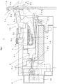
- Fig.1 to Fig.10 show the structure and operation of the flatbed knitting machine for pile knitting 1 serving as the example 1 according to the present invention.
- Fig.11 shows the structure of the capturing up-and-down means 30 in the flatbed knitting machine for pile knitting 21 serving as the example 2 according to the present invention.
- the corresponding portions in respective figures are denoted by common reference signs, and thus a duplicate description may be omitted. A portion not shown in a target figure for the sake of convenience, if any, may be described based on the reference sign in another figure.
- Fig.1 shows simplified major portions of the structure in the flatbed knitting machine for pile knitting 1 serving as the example 1 according to the present invention.
- the flatbed knitting machine for pile knitting 1 has needle beds 2 as shown in Fig.9 and Fig.10 , which are omitted to show in Fig.1 .
- the needle beds 2 are disposed in the manner that the front and rear needle beds 2 face each other and sandwich a needle bed gap 1a, so as to be planar symmetric with respect to a needle bed gap center plane 1b shown in Fig.1 .
- the portion of the needle bed gap 1a sandwiched by the front and rear needle beds 2 has an elongated rectangle shape, which is long in the depth direction in the figure when viewed from above.
- Each of the needle beds 2 which has a substantially rectangular shape with short sides and long sides, has needle grooves 2a parallel to the short side arranged in the longitudinal direction parallel to the long sides, and has one long side facing the needle bed gap 1a.
- the knitting needle 3 shown in Fig. 1 is housed in one of the needle grooves 2a.
- the knitting needle 3 has a hook 3a at its tip.
- Each of the knitting needles 3 to be housed in the needle grooves 2a is slidable so that the hook 3a advances to and retreats from the needle bed gap 1a.
- Fig. 1 shows the state of the needle grooves 2a inclined at the angle where the sliding direction of the knitting needles 3 corresponds to the vertical direction.
- Each of the knitting needles 3 is a latch needle which has the hook 3a and a latch 3b configured to open and close the hook 3a, but the latch 3b has no locking hook for knitting yarn, unlike Patent Citation 1.
- the flatbed knitting machine for pile knitting 1 includes the movable sinkers 4.
- Each of the sinkers 4 has a claw for ground yarn 4a, a claw for pile yarn 4b, and a pushing part 4c, which are disposed at the tip advancing to and retreating from between the knitting needles 3.
- Each of the sinkers 4 further has a spring 4d, a middle driving part 4e, and a tail driving part 4f, which are formed integrally.
- the spring 4d may be combined with a separate wire spring.
- a sinker bed 5 is provided above the needle beds 2 and has sinker grooves 5a arranged in parallel in the longitudinal direction, and the sinkers 4 are housed in the sinker grooves 5a, respectively.
- a carriage 6 reciprocates in the longitudinal direction, with respect to the needle beds 2 and the sinker bed 5.
- the carriage 6 is provided with a sinker advancing retreating mechanism 7.
- the sinker advancing retreating mechanism 7 includes an advancing retreating cam 7a.
- the advancing retreating cam 7a drives the sinkers 4 so that their tips advance to and retreat from between the knitting needles 3.
- the ground yarn 8a and the pile yarn 8b as knitting yarn are fed through a preceding yarn feeder 9a and a following yarn feeder 9b, respectively, to the needle bed gap 1a where the hooks 3a of the knitting needles 3 and the tips of the sinkers 4 advance and retreat.
- the sinker advancing retreating mechanism 7 in the present example 1 further includes the capturing up-and-down means 10.
- the capturing up-and-down means 10 prior to separating the ground yarn and the pile yarn, drives the sinker 4 to raise the tip in the needle bed gap 1a, and capture the ground yarn 8a fed through the yarn feeder 9a between the claw for ground yarn 4a and the claw for pile yarn 4b and thereafter draw the ground yarn 8a below the needle bed gap 1a.
- the sinker 4 which is at the time when driven to capture the ground yarn, is shown with the full line, and the knitting needle 3 at the same phase.
- the dashed lines show the state before the tip of the sinker 4 advances to between the knitting needles 3.
- the two-dot chain lines show the sinker 4 at the time when the pushing part 4c pushes an old loop, and the knitting needle 3 at the same phase.
- This state of the knitting needle 3 also corresponds to the sinker 4 shown by the dashed lines.
- the pushing operation is performed after the separation of the ground yarn 8a and the pile yarn 8b, the stitch formation by yarn drawing with the hook 3a, and stitch density decision.
- the sinker 4 is driven so that the tip once retreats from between the knitting needles 3 and re-advances to between the knitting needles 3, whereby the pushing part 4c can push the old loop staying in the vicinity of the needle bed gap 1a below the needle bed gap 1a.
- the sinker 4 In the pushing operation with the re-advancing, the sinker 4 is driven so that the tip advances over the bottom surface of the knitting needle 3 toward the needle bed gap 1a.
- the sinker advancing retreating mechanism 7 is able to separate the ground yarn 8a from the pile yarn 8b after the capturing up-and-down means 10 drives the sinker 4 to capture and draw the ground yarn 8a. Accordingly, it is possible to perform the pile knitting even when using the knitting needles 3 without a locking hook for knitting yarn.
- the knitting needle 3 may be a compound needle without the latch 3b.
- the capturing up-and-down means 10 in the present example 1 includes a rising cam 11 which raises the sinker 4 upwards in the needle bed gap 1a against the downward force by the spring 4d.
- the capturing up-and-down means 10 further includes a rising control cam 12 which controls the rising cam 11 not to rise excessively and ensures the rising and lowering.
- the capturing up-and-down means 10 may not include the rising control cam 12. In case of the sinker 4 without the spring 4d, the capturing up-and-down means 10 requires a cam for lowering the sinker 4.
- the rising cam 11 is arranged on the movement path for guiding the sinker 4 in advancing to and retreating from between the knitting needles 3, that is, in the sinker groove 5a of the sinker bed 5, so as to raise the tip of the sinker 4 upwards in the needle bed gap 1a.
- the ground yarn 8a is captured with the tip of the sinker 4 in conjunction with the advancing and retreating of the sinker 4.
- the rising control cam 12 pushes, from above, the middle driving part 4e of the sinker 4 raised by the rising cam 11.
- the part pushed by the rising control cam 12 is further away from the needle bed gap 1a than the part of the sinker 4 raised by the rising cam 11, whereby the tip of the sinker 4 rises while swinging.
- the spring 4d pushes the sinker 4 in the direction of lowering the tip of the sinker 4, and the tip of the sinker 4 is thus lowered when the sinker 4 is released from the raising force by the rising cam 11.
- To drive the sinkers 4 by the capturing up-and-down means 10 can be performed individually, if a selection mechanism similar to the needle selection mechanism for individually selecting the knitting needles 3 may be provided to select the sinkers 4 individually.
- the capturing up-and-down means 10 is switched between the operation of driving the sinkers 4 within a range covering the knitting width and not driving the sinkers 4 outside the range.
- the sinkers 4 being stopped with their tips raised upwards in the needle bed gap 1a may interfere with the yarn feeders 9a, 9b. In order to avoid the interference, all the sinkers 4 need to be lowered and the driving for one knitting course needs to be stopped. This lowers knitting efficiency. To prevent the lowering of knitting efficiency, the capturing up-and-down means 10 shall stop driving the sinkers 4 outside the range covering the knitting width.
- the interference between the sinkers 4 and the yarn feeders 9a, 9b may be avoided by the method of raising one feeder to be moved for switching in position in the yarn feeders 9a, 9b, or other method, whereby the conditions for yarn feeding are worsened.
- the interference may be avoided also by the method of using the mechanism for switching the yarn feeders 9a, 9b in height, whereby the mechanisms of the yarn feeders 9a, 9b are complicate.
- the capturing up-and-down means 10 in the present example 1 includes a pushing cam 13 and select jacks 14.
- the select jack 14 is provided between the sinker 4 and the bottom of the sinker groove 5a, and the select jack 14 allows selection of either an intermediary position for raising the tip of the sinker 4 upwards in needle bed gap 1a for the rising cam 11 or a non-intermediary position for not raising the tip of the sinker 4 upwards in the needle bed gap 1a for the rising cam 11, on the movement path.
- the select jack 14 has a selection part 14a on its tail side, and a pushing part 14b and a pressured part 14c on its upper tip side and its lower tip side, respectively.
- the selection part 14a receives selecting action performed by a switching cam 15.
- the pushing cam 13 ensures the selecting action by the switching cam 15, by pushing the selection part 14a downwards, but can be omitted.
- the full lines in the figure show the state where the selected select jack 14 receives the upward pressure by the rising cam 11 on the pressured part 14c, and thereby pushes the sinker 4 upwards with the pushing part 14b.
- the dashed lines show the select jack 14 when not selected.
- the select jack 14 is selected when the switching cam 15 is in the state shown by the full lines.
- An actuator 16 swings the switching cam 15, and the select jack 14 is not selected when the switching cam 15 is in the state shown by the one-dot chain lines in the figure.
- the switching cam 15 is used in two stages, and a select jack 14A and a select jack 14B shown in Fig.8 are used, so that it is possible for the sinkers 4 to be divided into two groups for selection.
- the select jack 14A having the selection part 14a on the upper side is subjected to the selection by the switching cam 15 when positioned upwards
- the select jack 14B having the selection part 14a on the lower side is subjected to the selection by the switching cam 15 positioned downwards.
- Each of the groups is formed with a plurality of sinkers adjacent in the longitudinal direction, where the number of groups may be three or greater, and the select jacks 14 and the switching cam 15 shall be provided according to the number of the groups.
- the sinkers 4 adjacent in the longitudinal direction may be selected individually.
- the sinkers 4 may be selected individually by a mechanism like a needle selection mechanism including a needle selection actuator to individually select a knitting needle 3.
- the selection mechanism selectively using the select jacks 14 for each group is simpler compared to the mechanism required in individual switching. In case of the pile knitting for a glove as in Patent Citation 1, the pile knitting is performed for each finger pouch. In this case, when the select jacks 14 are divided into two groups so that adjacent finger pouches belong to different groups, the select jacks 14 positioned outside the knitting width for a target finger pouch are not selected.
- Fig. 2 shows a state in which the select jack 14 is not selected by the capturing up-and-down means 10 shown in Fig. 1 .
- Fig. 3 shows a state in which the select jack 14 is selected by the capturing up-and-down means 10 shown in Fig. 1 .
- the select jack 14 when not selected is kept at a base-state position, while the sinker 4 advances and retreats.
- the select jack 14 when selected is moved by the switching cam 15 from the base-state position to the position where the pressured part 14c receives the push-up action performed by the rising cam 11.
- the select jack 14 acts as an intermediary to push up the sinker 4 with the pushing part 14b.
- the sinker 4 When the sinker 4 is pushed up while advancing into the needle bed gap 1a, the tip thereof is thus raised upwards in the needle bed gap 1a, whereby the sinker 4 can capture the ground yarn 8a fed through the yarn feeder 9a between the claw for ground yarn 4a and the claw for pile yarn 4b.
- the select jack 14 acting as an intermediary as in the present example 1 or the case of using the mechanism for directly selecting the sinker 4
- the sinker 4 when not selected performs the action of making the tip linearly advance to and retreat from the needle bed gap 1a, without performing the action of capturing the ground yarn 8a with the tip raised upwards in the needle bed gap 1a.
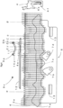
- Fig.4 is a plan view of the flatbed knitting machine for pile knitting 1 shown in Fig.1 , to show the trajectory of the sinkers 4, and a cam layout in the pile knitting.
- Fig.5 is a plan view of the flatbed knitting machine for pile knitting 1 shown in Fig. 1 , to show the trajectory of the knitting needles 3, and a cam layout in the pile knitting.
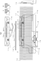
- Fig.6 is a plan view of the flatbed knitting machine for pile knitting 1 shown in Fig.1 , to show the trajectory of the select jacks 14 and a cam layout in the pile knitting. In each of the figures, it is assumed that the carriage 6 moves in the left direction, and the trajectory accordingly shifts in the right direction.
- an advancing retreating cam 7a and auxiliary movable cams 7b, 7c, 7d are mounted to drive the sinkers 4.
- the sinkers 4 advance into the needle bed gap 1a in response to the pressure by the cam surface shown on the upper side of the advancing retreating cam 7a in Fig.4 , and by the movable cams 7b, 7d.
- the pressure by the advancing retreating cam 7a is received on the part connected to the right side of the middle driving part 4e, in the side view shown on the right side of Fig.4 .
- the pressure by the movable cams 7b, 7d is received on the part on the lower side of the tail driving part 4f, in the side view on the right side of Fig.4 .
- a knitting cam 18 is further mounted to drive the knitting needles 3.
- Each of the knitting needles 3 is formed by the combination of a main body 3c having a hook 3a and a latch 3b, and a needle jack 3d connected to the tail part of the main body 3c.
- the knitting cam 18 includes a needle raising cam 18a, a center cam 18b, a retractable cam for set up 18c, a stitch cam 18d, a guide cam 18e, and an elastic raising cam 18f, which act on a butt 3e of the needle jack 3d.
- the retractable cam for set up 18c protrudes in setting up and drives the knitting needles 3 when the carriage 6 moves in the right direction.
- the elastic raising cam 18f is used for tucking with elastic yarn fed through a yarn feeder 9c.
- the rising cam 11 includes returning cam surfaces 11b, 11c for returning the select jacks 14 having moved toward the needle bed gap 1a in response to the action by the switching cam 15, to the base-state position corresponding to the position shown in Fig.2 .
- the rising control cam 12 pushes the middle driving part 4e of the sinker 4.
- An arrow A-A and an arrow B-B shown on the upper side of Fig.6 show a sectional view A and a sectional view B related to a rising cam surface 11a, respectively.
- Fig.4 and Fig.5 show major phases ⁇ , ⁇ , ⁇ , ⁇ , ⁇ , ⁇ , ⁇ , ⁇ , ⁇ related to the sinkers 4 driven by the capturing up-and-down means 10.
- the dashed lines in Fig.1 correspond to the phase ⁇ ; the full lines correspond to the phase ⁇ ; and the two-dot chain lines correspond to the phase ⁇ , respectively.
- the phase ⁇ also corresponds to the dashed lines in Fig.3
- the full lines in Fig. 3 correspond to the phase ⁇ .
- a glove as in Patent Citation 1
- basically a bag-shaped fabric is knitted by alternate using the needle beds 2 facing each other.
- the opposed side needle bed 2 is used, and a similar basic cam layout is used.
- the sinker 4 is capable of capturing the ground yarn 8a, whereby the pile knitting is performed.
- the sinker 4 when raised is capable of capturing both the ground yarn 8a and the pile yarn 8b, whereby the plain knitting is performed.
- the plain knitting which is performed by capturing both the ground yarn 8a and the pile yarn 8b, is performed also when the yarn feeders 9a, 9b are changed in position.
- the phase ⁇ corresponds to the phase just before the completion of stitch density decision after the stitch formation by the drawing action performed by the stitch cam 18c.
- the sinker 4 is driven so that the tip briefly retreats from between the knitting needles 3.
- the sinker 4 is driven so that the tip re-advances to between the knitting needles 3.
- an old loop having been knocked over may stay in the vicinity of the needle bed gap 1a.
- the pushing part 4c provided at the tip of the sinker 4 pushes the old loop below the needle bed gap, so that stable knitting can be performed.
- the yarn feeders 9a, 9b may be a coupling type feeder which moves together with the carriage 6 moving, the yarn feeders 9a, 9b preferably move independently from the carriage 6.
- the use of the independently movable yarn feeders 9a, 9b leads to an increase in efficiency.
- the pile knit and the plain knit may be switched per course so as to be mixed in the wale direction. Even in the middle of one course, the pile knitting and the plain knitting may be switched by once stopping the knitting, changing the gap between the yarn feeders 9a, 9b, and restarting the knitting.
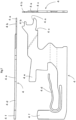
- Fig.7 and Fig.8 show shapes of the sinker 4 and the select jack 14 shown in Fig. 1 , respectively.
- the sinker 4 separates the ground yarn 8a and the pile yarn 8b with the tip, basically as in Patent Citation 1.
- the pushing part 4c is preferably formed in a hook shape, alternatively, the pushing part 4c for pushing the old loop may be formed in a flat wall shape or a smooth curve shape.
- the select jack 14 includes several types respectively having the selection parts 14a formed in different shapes corresponding to respective groups.
- the switching cam 15 when positioned higher or lower shown in Fig.1 selects either group of the select jacks 14A each having the selection part 14a on the upper side and the select jacks 14B each having the selection part 14a on the lower side, by dividing them into two groups.
- the select jacks 14 may be divided into two groups.
- select jacks 14C each having the selection part 14a as in the figure may be selected by the switching cam 15 whether positioned higher or lower.
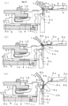
- Fig.9 and Fig. 10 show the flatbed knitting machine for pile knitting 1 shown in Fig. 1 , to operate the sinker 4 for capturing the ground yarn 8a at the phases ⁇ , ⁇ , ⁇ , and for separation at the phases ⁇ , ⁇ , ⁇ , respectively.
- the yarn feeders 9a, 9b are changed in moving direction, in the manner that the yarn feeders 9a, 9b first move in the direction toward the front perpendicular to the sheet surface, and the ground yarn 8a and the pile yarn 8b are fed to the hook 3a of the last knitting needle 3 in the knitting width in the rear needle bed 2 shown on the right side of the figures, and thereafter, the yarn feeders 9a, 9b move in the direction toward the back perpendicular to the sheet surface, to perform the pile knitting by use of the front needle bed 2 shown on the left side of the figures.
- the knitting needles 3 are respectively housed in the needle grooves 2a of the front and rear needle beds 2. At the phase ⁇ , the tip of the sinker 4 is raised.
- the yarn feeder 9a has already passed to the back perpendicular to the sheet surface, and the ground yarn 8a fed through the yarn feeder 9a is hung and hooked by the hook 3a of the knitting needle 3 in the rear needle bed 2.
- the sinker 4 is driven so that the tip advances into the needle bed gap 1a and captures the ground yarn 8a between the claw for ground yarn 4a and the claw for pile yarn 4b.
- the sinker 4 is driven to lower the tip, start drawing the ground yarn 8a downwards, and complete the capturing.
- the pile yarn 8b fed through the yarn feeder 9b is hooked by the hook 3a of the rear knitting needle 3 and hung above the claw for pile yarn 4b and is accordingly separated from the ground yarn 8a captured under the claw for pile yarn 4b.
- the hook 3a of the knitting needle 3 starts drawing.
- the knitting needle 3 keeps drawing, and an old loop is knocked over when the latch 3b is closed, and this is just before the completion of stitch density decision.
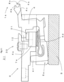
- Fig. 11 shows a simplified structure of capturing up-and-down means 30 in the example 2 according to the present invention.
- the capturing up-and-down means 30 in the flatbed knitting machine for pile knitting 21 serving as the present example 2 the advancing retreating cam 7a is equipped with a rising cam 31. Since the capturing up-and-down means 30 has no mechanism for selecting the sinkers 4, all the sinkers 4 are uniformly raised to capture the ground yarn 8a. In the case where all the sinkers 4 are driven to capture the ground yarn 8a, the capturing up-and-down means 30 has a simple configuration. In order to drive the sinker 4 to capture the ground yarn 8a, the bottom of the sinker groove 5a may be formed in a curved shape similar to the shape of the rising cam.
- the sinker 4 may be guided along a guide groove, in the manner that the guide groove is provided on the side surface of the sinker groove 5a, and that a pin is arranged to protrude from the side surface of the sinker 4.
- the sinker 4 advances and retreats linearly, and additionally rises and swings in the middle of the linear moving to capture the ground yarn 8a.
- the sinker 4 while swinging may capture the ground yarn 8a.
Landscapes
- Engineering & Computer Science (AREA)
- Textile Engineering (AREA)
- Knitting Machines (AREA)
- Knitting Of Fabric (AREA)
Applications Claiming Priority (1)
| Application Number | Priority Date | Filing Date | Title |
|---|---|---|---|
| JP2022138749A JP7580433B2 (ja) | 2022-08-31 | 2022-08-31 | パイル編成用横編機およびパイル編成方法 |
Publications (2)
| Publication Number | Publication Date |
|---|---|
| EP4332286A1 true EP4332286A1 (de) | 2024-03-06 |
| EP4332286B1 EP4332286B1 (de) | 2024-09-11 |
Family
ID=87863167
Family Applications (1)
| Application Number | Title | Priority Date | Filing Date |
|---|---|---|---|
| EP23194340.8A Active EP4332286B1 (de) | 2022-08-31 | 2023-08-30 | Flachstrickmaschine für polstricken und polstrickverfahren |
Country Status (4)
| Country | Link |
|---|---|
| EP (1) | EP4332286B1 (de) |
| JP (1) | JP7580433B2 (de) |
| KR (1) | KR102880772B1 (de) |
| CN (1) | CN117626518A (de) |
Cited By (1)
| Publication number | Priority date | Publication date | Assignee | Title |
|---|---|---|---|---|
| US20260103829A1 (en) * | 2024-10-14 | 2026-04-16 | Pai Lung Machinery Mill Co., Ltd. | Circular knitting machine for knitting double-sided yarn-dyed fabric |
Families Citing this family (1)
| Publication number | Priority date | Publication date | Assignee | Title |
|---|---|---|---|---|
| CN118792798B (zh) * | 2024-08-05 | 2025-09-09 | 浙江睿丰智能科技有限公司 | 一种沉降片控制方法 |
Citations (4)
| Publication number | Priority date | Publication date | Assignee | Title |
|---|---|---|---|---|
| US3643472A (en) * | 1968-08-13 | 1972-02-22 | Harry Apprich | Apparatus for producing a looped fabric |
| JPS5643454A (en) * | 1979-09-13 | 1981-04-22 | Shima Idea Center | Pile knitting method |
| JPS5658037A (en) * | 1979-10-17 | 1981-05-20 | Shima Idea Center | Pile hand glove and knitting same |
| DE10349845A1 (de) * | 2002-11-01 | 2004-05-13 | Precision Fukuhara Works, Ltd., Kobe | Strickverfahren für Jacquardflor und für Platinen, die in dem Verfahren verwendet werden |
Family Cites Families (5)
| Publication number | Priority date | Publication date | Assignee | Title |
|---|---|---|---|---|
| JP4176038B2 (ja) * | 2004-03-31 | 2008-11-05 | 株式会社島精機製作所 | 横編機の可動シンカー装置 |
| KR101209644B1 (ko) * | 2005-12-27 | 2012-12-07 | 가부시키가이샤 시마세이키 세이사쿠쇼 | 횡편기의 선침장치 |
| JP6177263B2 (ja) * | 2015-02-03 | 2017-08-09 | 株式会社島精機製作所 | 可動シンカーを備える横編機 |
| JP7271398B2 (ja) * | 2019-11-15 | 2023-05-11 | 株式会社島精機製作所 | パイル編み用横編機および編成方法 |
| JP7438011B2 (ja) * | 2020-04-30 | 2024-02-26 | 株式会社島精機製作所 | 横編機によるパイル編地の編成方法 |
-
2022
- 2022-08-31 JP JP2022138749A patent/JP7580433B2/ja active Active
-
2023
- 2023-08-30 CN CN202311107515.7A patent/CN117626518A/zh active Pending
- 2023-08-30 KR KR1020230114480A patent/KR102880772B1/ko active Active
- 2023-08-30 EP EP23194340.8A patent/EP4332286B1/de active Active
Patent Citations (5)
| Publication number | Priority date | Publication date | Assignee | Title |
|---|---|---|---|---|
| US3643472A (en) * | 1968-08-13 | 1972-02-22 | Harry Apprich | Apparatus for producing a looped fabric |
| JPS5643454A (en) * | 1979-09-13 | 1981-04-22 | Shima Idea Center | Pile knitting method |
| JPS5658037A (en) * | 1979-10-17 | 1981-05-20 | Shima Idea Center | Pile hand glove and knitting same |
| JPS6120668B2 (de) | 1979-10-17 | 1986-05-23 | Shima Idea Center Co Ltd | |
| DE10349845A1 (de) * | 2002-11-01 | 2004-05-13 | Precision Fukuhara Works, Ltd., Kobe | Strickverfahren für Jacquardflor und für Platinen, die in dem Verfahren verwendet werden |
Cited By (1)
| Publication number | Priority date | Publication date | Assignee | Title |
|---|---|---|---|---|
| US20260103829A1 (en) * | 2024-10-14 | 2026-04-16 | Pai Lung Machinery Mill Co., Ltd. | Circular knitting machine for knitting double-sided yarn-dyed fabric |
Also Published As
| Publication number | Publication date |
|---|---|
| JP2024034491A (ja) | 2024-03-13 |
| JP7580433B2 (ja) | 2024-11-11 |
| KR20240031145A (ko) | 2024-03-07 |
| CN117626518A (zh) | 2024-03-01 |
| KR102880772B1 (ko) | 2025-11-03 |
| EP4332286B1 (de) | 2024-09-11 |
Similar Documents
| Publication | Publication Date | Title |
|---|---|---|
| US6079233A (en) | Flat knitting machine with movable loop forming plates | |
| EP4332286B1 (de) | Flachstrickmaschine für polstricken und polstrickverfahren | |
| US7207194B2 (en) | Weft knitting machine with movable yarn guide member | |
| KR100249119B1 (ko) | 눈옮김장치를 가진 횡편기 | |
| JP7483257B2 (ja) | 丸編機におけるジャカード編地編成機構、その編成機構を用いた編成方法及びその編成機構で用いられるシンカー | |
| KR102226578B1 (ko) | 횡편기 | |
| CN101351587B (zh) | 横机的选针装置 | |
| EP2570535B1 (de) | Flachstrickmaschine mit Schiebernadel, sowie Verfahren zur Betätigung des Schiebers für eine Flachstrickmaschine | |
| EP2942428B1 (de) | Verfahren zum split-stricken | |
| EP0751248A1 (de) | Strick- und Umhängeschlossteil für Flachstrickmaschine | |
| KR101065245B1 (ko) | 편사의 지지절단 방법 및 장치 | |
| EP2390395B1 (de) | Flachstrickmaschine und dazugehöriges maschenübertragungsverfahren | |
| EP2002043B1 (de) | Zweizylindrige rundstrickmaschine für miederwaren und andere strickwaren | |
| CN110678593B (zh) | 横机中的添纱编织方法 | |
| KR100768347B1 (ko) | 코이동 기구를 구비하는 횡편기 및 코이동 방법 | |
| CN105239264B (zh) | 一种复合三角系统 | |
| JPH07324259A (ja) | インターシャ編地の編成方法及びそれを実施するためのカムロック | |
| KR102745800B1 (ko) | 파일편성용 횡편기 및 싱커, 및 횡편기에 의한 파일편성방법 | |
| EP4306698A1 (de) | Verfahren zum stricken von durch eine flachstrickmaschine hergestellten maschenketten-gestricken | |
| CN115074897B (zh) | 由横编机编织的绒头编织物的编织方法 |
Legal Events
| Date | Code | Title | Description |
|---|---|---|---|
| PUAI | Public reference made under article 153(3) epc to a published international application that has entered the european phase |
Free format text: ORIGINAL CODE: 0009012 |
|
| STAA | Information on the status of an ep patent application or granted ep patent |
Free format text: STATUS: THE APPLICATION HAS BEEN PUBLISHED |
|
| AK | Designated contracting states |
Kind code of ref document: A1 Designated state(s): AL AT BE BG CH CY CZ DE DK EE ES FI FR GB GR HR HU IE IS IT LI LT LU LV MC ME MK MT NL NO PL PT RO RS SE SI SK SM TR |
|
| STAA | Information on the status of an ep patent application or granted ep patent |
Free format text: STATUS: REQUEST FOR EXAMINATION WAS MADE |
|
| REG | Reference to a national code |
Ref country code: DE Ref legal event code: R079 Free format text: PREVIOUS MAIN CLASS: D04B0007120000 Ipc: D04B0035020000 Ref country code: DE Ref legal event code: R079 Ref document number: 602023000541 Country of ref document: DE Free format text: PREVIOUS MAIN CLASS: D04B0007120000 Ipc: D04B0035020000 |
|
| 17P | Request for examination filed |
Effective date: 20240326 |
|
| RBV | Designated contracting states (corrected) |
Designated state(s): AL AT BE BG CH CY CZ DE DK EE ES FI FR GB GR HR HU IE IS IT LI LT LU LV MC ME MK MT NL NO PL PT RO RS SE SI SK SM TR |
|
| GRAP | Despatch of communication of intention to grant a patent |
Free format text: ORIGINAL CODE: EPIDOSNIGR1 |
|
| STAA | Information on the status of an ep patent application or granted ep patent |
Free format text: STATUS: GRANT OF PATENT IS INTENDED |
|
| RIC1 | Information provided on ipc code assigned before grant |
Ipc: D04B 15/70 20060101ALI20240412BHEP Ipc: D04B 15/36 20060101ALI20240412BHEP Ipc: D04B 15/06 20060101ALI20240412BHEP Ipc: D04B 7/12 20060101ALI20240412BHEP Ipc: D04B 35/02 20060101AFI20240412BHEP |
|
| INTG | Intention to grant announced |
Effective date: 20240503 |
|
| GRAS | Grant fee paid |
Free format text: ORIGINAL CODE: EPIDOSNIGR3 |
|
| GRAA | (expected) grant |
Free format text: ORIGINAL CODE: 0009210 |
|
| STAA | Information on the status of an ep patent application or granted ep patent |
Free format text: STATUS: THE PATENT HAS BEEN GRANTED |
|
| AK | Designated contracting states |
Kind code of ref document: B1 Designated state(s): AL AT BE BG CH CY CZ DE DK EE ES FI FR GB GR HR HU IE IS IT LI LT LU LV MC ME MK MT NL NO PL PT RO RS SE SI SK SM TR |
|
| REG | Reference to a national code |
Ref country code: GB Ref legal event code: FG4D |
|
| REG | Reference to a national code |
Ref country code: CH Ref legal event code: EP |
|
| REG | Reference to a national code |
Ref country code: DE Ref legal event code: R096 Ref document number: 602023000541 Country of ref document: DE |
|
| REG | Reference to a national code |
Ref country code: IE Ref legal event code: FG4D |
|
| REG | Reference to a national code |
Ref country code: LT Ref legal event code: MG9D |
|
| PG25 | Lapsed in a contracting state [announced via postgrant information from national office to epo] |
Ref country code: NO Free format text: LAPSE BECAUSE OF FAILURE TO SUBMIT A TRANSLATION OF THE DESCRIPTION OR TO PAY THE FEE WITHIN THE PRESCRIBED TIME-LIMIT Effective date: 20241211 |
|
| REG | Reference to a national code |
Ref country code: NL Ref legal event code: MP Effective date: 20240911 |
|
| PG25 | Lapsed in a contracting state [announced via postgrant information from national office to epo] |
Ref country code: GR Free format text: LAPSE BECAUSE OF FAILURE TO SUBMIT A TRANSLATION OF THE DESCRIPTION OR TO PAY THE FEE WITHIN THE PRESCRIBED TIME-LIMIT Effective date: 20241212 Ref country code: FI Free format text: LAPSE BECAUSE OF FAILURE TO SUBMIT A TRANSLATION OF THE DESCRIPTION OR TO PAY THE FEE WITHIN THE PRESCRIBED TIME-LIMIT Effective date: 20240911 |
|
| PG25 | Lapsed in a contracting state [announced via postgrant information from national office to epo] |
Ref country code: BG Free format text: LAPSE BECAUSE OF FAILURE TO SUBMIT A TRANSLATION OF THE DESCRIPTION OR TO PAY THE FEE WITHIN THE PRESCRIBED TIME-LIMIT Effective date: 20240911 |
|
| PG25 | Lapsed in a contracting state [announced via postgrant information from national office to epo] |
Ref country code: LV Free format text: LAPSE BECAUSE OF FAILURE TO SUBMIT A TRANSLATION OF THE DESCRIPTION OR TO PAY THE FEE WITHIN THE PRESCRIBED TIME-LIMIT Effective date: 20240911 |
|
| PG25 | Lapsed in a contracting state [announced via postgrant information from national office to epo] |
Ref country code: HR Free format text: LAPSE BECAUSE OF FAILURE TO SUBMIT A TRANSLATION OF THE DESCRIPTION OR TO PAY THE FEE WITHIN THE PRESCRIBED TIME-LIMIT Effective date: 20240911 |
|
| PG25 | Lapsed in a contracting state [announced via postgrant information from national office to epo] |
Ref country code: ES Free format text: LAPSE BECAUSE OF FAILURE TO SUBMIT A TRANSLATION OF THE DESCRIPTION OR TO PAY THE FEE WITHIN THE PRESCRIBED TIME-LIMIT Effective date: 20240911 Ref country code: RS Free format text: LAPSE BECAUSE OF FAILURE TO SUBMIT A TRANSLATION OF THE DESCRIPTION OR TO PAY THE FEE WITHIN THE PRESCRIBED TIME-LIMIT Effective date: 20241211 |
|
| PG25 | Lapsed in a contracting state [announced via postgrant information from national office to epo] |
Ref country code: RS Free format text: LAPSE BECAUSE OF FAILURE TO SUBMIT A TRANSLATION OF THE DESCRIPTION OR TO PAY THE FEE WITHIN THE PRESCRIBED TIME-LIMIT Effective date: 20241211 Ref country code: NO Free format text: LAPSE BECAUSE OF FAILURE TO SUBMIT A TRANSLATION OF THE DESCRIPTION OR TO PAY THE FEE WITHIN THE PRESCRIBED TIME-LIMIT Effective date: 20241211 Ref country code: LV Free format text: LAPSE BECAUSE OF FAILURE TO SUBMIT A TRANSLATION OF THE DESCRIPTION OR TO PAY THE FEE WITHIN THE PRESCRIBED TIME-LIMIT Effective date: 20240911 Ref country code: HR Free format text: LAPSE BECAUSE OF FAILURE TO SUBMIT A TRANSLATION OF THE DESCRIPTION OR TO PAY THE FEE WITHIN THE PRESCRIBED TIME-LIMIT Effective date: 20240911 Ref country code: GR Free format text: LAPSE BECAUSE OF FAILURE TO SUBMIT A TRANSLATION OF THE DESCRIPTION OR TO PAY THE FEE WITHIN THE PRESCRIBED TIME-LIMIT Effective date: 20241212 Ref country code: FI Free format text: LAPSE BECAUSE OF FAILURE TO SUBMIT A TRANSLATION OF THE DESCRIPTION OR TO PAY THE FEE WITHIN THE PRESCRIBED TIME-LIMIT Effective date: 20240911 Ref country code: ES Free format text: LAPSE BECAUSE OF FAILURE TO SUBMIT A TRANSLATION OF THE DESCRIPTION OR TO PAY THE FEE WITHIN THE PRESCRIBED TIME-LIMIT Effective date: 20240911 Ref country code: BG Free format text: LAPSE BECAUSE OF FAILURE TO SUBMIT A TRANSLATION OF THE DESCRIPTION OR TO PAY THE FEE WITHIN THE PRESCRIBED TIME-LIMIT Effective date: 20240911 |
|
| REG | Reference to a national code |
Ref country code: AT Ref legal event code: MK05 Ref document number: 1722751 Country of ref document: AT Kind code of ref document: T Effective date: 20240911 |
|
| PG25 | Lapsed in a contracting state [announced via postgrant information from national office to epo] |
Ref country code: NL Free format text: LAPSE BECAUSE OF FAILURE TO SUBMIT A TRANSLATION OF THE DESCRIPTION OR TO PAY THE FEE WITHIN THE PRESCRIBED TIME-LIMIT Effective date: 20240911 |
|
| PG25 | Lapsed in a contracting state [announced via postgrant information from national office to epo] |
Ref country code: IS Free format text: LAPSE BECAUSE OF FAILURE TO SUBMIT A TRANSLATION OF THE DESCRIPTION OR TO PAY THE FEE WITHIN THE PRESCRIBED TIME-LIMIT Effective date: 20250111 Ref country code: PT Free format text: LAPSE BECAUSE OF FAILURE TO SUBMIT A TRANSLATION OF THE DESCRIPTION OR TO PAY THE FEE WITHIN THE PRESCRIBED TIME-LIMIT Effective date: 20250113 |
|
| PG25 | Lapsed in a contracting state [announced via postgrant information from national office to epo] |
Ref country code: RO Free format text: LAPSE BECAUSE OF FAILURE TO SUBMIT A TRANSLATION OF THE DESCRIPTION OR TO PAY THE FEE WITHIN THE PRESCRIBED TIME-LIMIT Effective date: 20240911 Ref country code: SM Free format text: LAPSE BECAUSE OF FAILURE TO SUBMIT A TRANSLATION OF THE DESCRIPTION OR TO PAY THE FEE WITHIN THE PRESCRIBED TIME-LIMIT Effective date: 20240911 |
|
| PG25 | Lapsed in a contracting state [announced via postgrant information from national office to epo] |
Ref country code: AT Free format text: LAPSE BECAUSE OF FAILURE TO SUBMIT A TRANSLATION OF THE DESCRIPTION OR TO PAY THE FEE WITHIN THE PRESCRIBED TIME-LIMIT Effective date: 20240911 Ref country code: EE Free format text: LAPSE BECAUSE OF FAILURE TO SUBMIT A TRANSLATION OF THE DESCRIPTION OR TO PAY THE FEE WITHIN THE PRESCRIBED TIME-LIMIT Effective date: 20240911 |
|
| PG25 | Lapsed in a contracting state [announced via postgrant information from national office to epo] |
Ref country code: CZ Free format text: LAPSE BECAUSE OF FAILURE TO SUBMIT A TRANSLATION OF THE DESCRIPTION OR TO PAY THE FEE WITHIN THE PRESCRIBED TIME-LIMIT Effective date: 20240911 Ref country code: PL Free format text: LAPSE BECAUSE OF FAILURE TO SUBMIT A TRANSLATION OF THE DESCRIPTION OR TO PAY THE FEE WITHIN THE PRESCRIBED TIME-LIMIT Effective date: 20240911 |
|
| PG25 | Lapsed in a contracting state [announced via postgrant information from national office to epo] |
Ref country code: SK Free format text: LAPSE BECAUSE OF FAILURE TO SUBMIT A TRANSLATION OF THE DESCRIPTION OR TO PAY THE FEE WITHIN THE PRESCRIBED TIME-LIMIT Effective date: 20240911 |
|
| REG | Reference to a national code |
Ref country code: DE Ref legal event code: R097 Ref document number: 602023000541 Country of ref document: DE |
|
| PG25 | Lapsed in a contracting state [announced via postgrant information from national office to epo] |
Ref country code: DK Free format text: LAPSE BECAUSE OF FAILURE TO SUBMIT A TRANSLATION OF THE DESCRIPTION OR TO PAY THE FEE WITHIN THE PRESCRIBED TIME-LIMIT Effective date: 20240911 |
|
| PLBE | No opposition filed within time limit |
Free format text: ORIGINAL CODE: 0009261 |
|
| STAA | Information on the status of an ep patent application or granted ep patent |
Free format text: STATUS: NO OPPOSITION FILED WITHIN TIME LIMIT |
|
| 26N | No opposition filed |
Effective date: 20250612 |
|
| PG25 | Lapsed in a contracting state [announced via postgrant information from national office to epo] |
Ref country code: SE Free format text: LAPSE BECAUSE OF FAILURE TO SUBMIT A TRANSLATION OF THE DESCRIPTION OR TO PAY THE FEE WITHIN THE PRESCRIBED TIME-LIMIT Effective date: 20240911 |
|
| PGFP | Annual fee paid to national office [announced via postgrant information from national office to epo] |
Ref country code: DE Payment date: 20250702 Year of fee payment: 3 |
|
| PGFP | Annual fee paid to national office [announced via postgrant information from national office to epo] |
Ref country code: IT Payment date: 20250901 Year of fee payment: 3 |
|
| PG25 | Lapsed in a contracting state [announced via postgrant information from national office to epo] |
Ref country code: MC Free format text: LAPSE BECAUSE OF FAILURE TO SUBMIT A TRANSLATION OF THE DESCRIPTION OR TO PAY THE FEE WITHIN THE PRESCRIBED TIME-LIMIT Effective date: 20240911 |
|
| PG25 | Lapsed in a contracting state [announced via postgrant information from national office to epo] |
Ref country code: LU Free format text: LAPSE BECAUSE OF NON-PAYMENT OF DUE FEES Effective date: 20250830 |