EP4332527A2 - Dispositif comprenant un compartiment pour contenir un liquide - Google Patents
Dispositif comprenant un compartiment pour contenir un liquide Download PDFInfo
- Publication number
- EP4332527A2 EP4332527A2 EP23215969.9A EP23215969A EP4332527A2 EP 4332527 A2 EP4332527 A2 EP 4332527A2 EP 23215969 A EP23215969 A EP 23215969A EP 4332527 A2 EP4332527 A2 EP 4332527A2
- Authority
- EP
- European Patent Office
- Prior art keywords
- base body
- holding groove
- longitudinal holding
- temperature sensor
- body segment
- Prior art date
- Legal status (The legal status is an assumption and is not a legal conclusion. Google has not performed a legal analysis and makes no representation as to the accuracy of the status listed.)
- Pending
Links
Images


Classifications
-
- G—PHYSICS
- G01—MEASURING; TESTING
- G01K—MEASURING TEMPERATURE; MEASURING QUANTITY OF HEAT; THERMALLY-SENSITIVE ELEMENTS NOT OTHERWISE PROVIDED FOR
- G01K1/00—Details of thermometers not specially adapted for particular types of thermometer
- G01K1/14—Supports; Fastening devices; Arrangements for mounting thermometers in particular locations
-
- F—MECHANICAL ENGINEERING; LIGHTING; HEATING; WEAPONS; BLASTING
- F24—HEATING; RANGES; VENTILATING
- F24F—AIR-CONDITIONING; AIR-HUMIDIFICATION; VENTILATION; USE OF AIR CURRENTS FOR SCREENING
- F24F11/00—Control or safety arrangements
- F24F11/89—Arrangement or mounting of control or safety devices
-
- F—MECHANICAL ENGINEERING; LIGHTING; HEATING; WEAPONS; BLASTING
- F24—HEATING; RANGES; VENTILATING
- F24H—FLUID HEATERS, e.g. WATER OR AIR HEATERS, HAVING HEAT-GENERATING MEANS, e.g. HEAT PUMPS, IN GENERAL
- F24H3/00—Air heaters
- F24H3/002—Air heaters using electric energy supply
-
- F—MECHANICAL ENGINEERING; LIGHTING; HEATING; WEAPONS; BLASTING
- F24—HEATING; RANGES; VENTILATING
- F24H—FLUID HEATERS, e.g. WATER OR AIR HEATERS, HAVING HEAT-GENERATING MEANS, e.g. HEAT PUMPS, IN GENERAL
- F24H9/00—Details
- F24H9/20—Arrangement or mounting of control or safety devices
- F24H9/2007—Arrangement or mounting of control or safety devices for water heaters
-
- G—PHYSICS
- G01—MEASURING; TESTING
- G01K—MEASURING TEMPERATURE; MEASURING QUANTITY OF HEAT; THERMALLY-SENSITIVE ELEMENTS NOT OTHERWISE PROVIDED FOR
- G01K13/00—Thermometers specially adapted for specific purposes
- G01K13/02—Thermometers specially adapted for specific purposes for measuring temperature of moving fluids or granular materials capable of flow
- G01K13/026—Thermometers specially adapted for specific purposes for measuring temperature of moving fluids or granular materials capable of flow of moving liquids
-
- F—MECHANICAL ENGINEERING; LIGHTING; HEATING; WEAPONS; BLASTING
- F24—HEATING; RANGES; VENTILATING
- F24D—DOMESTIC- OR SPACE-HEATING SYSTEMS, e.g. CENTRAL HEATING SYSTEMS; DOMESTIC HOT-WATER SUPPLY SYSTEMS; ELEMENTS OR COMPONENTS THEREFOR
- F24D3/00—Hot-water central heating systems
- F24D3/08—Hot-water central heating systems in combination with systems for domestic hot-water supply
- F24D3/082—Hot water storage tanks specially adapted therefor
-
- F—MECHANICAL ENGINEERING; LIGHTING; HEATING; WEAPONS; BLASTING
- F24—HEATING; RANGES; VENTILATING
- F24F—AIR-CONDITIONING; AIR-HUMIDIFICATION; VENTILATION; USE OF AIR CURRENTS FOR SCREENING
- F24F13/00—Details common to, or for air-conditioning, air-humidification, ventilation or use of air currents for screening
- F24F13/32—Supports for air-conditioning, air-humidification or ventilation units
-
- F—MECHANICAL ENGINEERING; LIGHTING; HEATING; WEAPONS; BLASTING
- F24—HEATING; RANGES; VENTILATING
- F24F—AIR-CONDITIONING; AIR-HUMIDIFICATION; VENTILATION; USE OF AIR CURRENTS FOR SCREENING
- F24F5/00—Air-conditioning systems or apparatus not covered by F24F1/00 or F24F3/00, e.g. using solar heat or combined with household units such as an oven or water heater
- F24F5/0007—Air-conditioning systems or apparatus not covered by F24F1/00 or F24F3/00, e.g. using solar heat or combined with household units such as an oven or water heater cooling apparatus specially adapted for use in air-conditioning
- F24F5/0017—Air-conditioning systems or apparatus not covered by F24F1/00 or F24F3/00, e.g. using solar heat or combined with household units such as an oven or water heater cooling apparatus specially adapted for use in air-conditioning using cold storage bodies, e.g. ice
- F24F2005/0025—Air-conditioning systems or apparatus not covered by F24F1/00 or F24F3/00, e.g. using solar heat or combined with household units such as an oven or water heater cooling apparatus specially adapted for use in air-conditioning using cold storage bodies, e.g. ice using heat exchange fluid storage tanks
Definitions
- the invention relates to a device with a receiving space for a liquid and a temperature measuring device located in the receiving space, which has an immersion tube with at least one temperature sensor, a holding device for the at least one temperature sensor being inserted into the interior of the immersion tube, which holding device has at least one elongated base body segment with at least one longitudinal holding groove, wherein the at least one temperature sensor is accommodated in the at least one longitudinal holding groove of the at least one base body segment, wherein a temperature sensor head of the temperature sensor protrudes at least partially from the longitudinal holding groove of the base body segment.
- Immersion tubes with temperature sensors inside are used to measure the temperature of a liquid, for example in the receiving space of a hot water tank.
- a temperature sensor within a dip tube and to transmit the temperature of the liquid to the temperature sensor as unaltered as possible, various methods and devices are known from the prior art.
- the fixing device has the shape of a star, and a temperature sensor can be accommodated in the recesses between the protruding points. Due to the resilient effect of the sheet metal, the temperature sensors are pressed against the inner wall of the immersion tube.
- a disadvantage of the prior art is that the temperature sensors are displaced from their original position in the immersion tube when forces are applied, for example vibrations or during assembly work. As a result, the temperature of the surrounding liquid is no longer measured at the actually intended location. Furthermore, in the state of the art, inserting the temperature sensors into the immersion tubes is relatively complicated and sometimes prone to errors. This makes it more difficult to replace defective temperature sensors and leads to increased effort and costs during installation. In addition, with the state of the art, the exact placement of the temperature sensors within the immersion tube is difficult or not possible at all, which is, however, of essential importance, especially in metrological applications in which it is important to measure the temperature at a specific point.
- the object of the present invention to alleviate or completely eliminate the disadvantages of the prior art.
- the temperature sensor can first be inserted into the longitudinal holding groove and then the base body segment can be inserted into the dip tube together with the temperature sensor, whereby the insertion and positioning of the temperature sensor can be done in a simple manner can.
- the temperature sensor can be provided that the temperature sensor is received in the longitudinal holding groove in a frictional and/or form-fitting manner.
- the position of the temperature sensor in the longitudinal holding groove is essentially maintained during insertion, whereby the position of the temperature sensor can be precisely specified by positioning the base body segment in the immersion tube.
- the temperature sensor can also be glued into the longitudinal holding groove or attached in some other way.
- the base body segment can - apart from the longitudinal holding groove - essentially be cylindrical. However, it would also be conceivable for the base body segment to have a different shape, for example a cuboid shape.
- the shape of the base body segment primarily depends on the shape of the immersion tube into which the base body segment is to be inserted.
- the base body segment can be designed as a solid part, ie without internal cavities.
- the base body segment is elongated in shape, which means that the base body segment has the greatest extent along the axis along which the base body segment is inserted into the dip tube during assembly. This axis is also referred to as the longitudinal axis of the base body segment.
- the base body segment is preferably made of plastic.
- the holding device can in principle consist of a single base body segment or of several, in particular similar, base body segments.
- the longitudinal holding groove has an opening on the outside of the base body segment and is therefore open to the outside, that is, away from the longitudinal axis, so that a temperature sensor can be inserted into the longitudinal holding groove from this side.
- the cross section of the longitudinal holding groove can have different shapes, for example round or n-square. However, it is preferably provided that the longitudinal holding groove is at least partially round, in particular partially circular.
- the cross section of the longitudinal holding groove can be the same along its entire length.
- the longitudinal holding groove is straight (ie free of bends) and runs essentially parallel to the longitudinal axis of the base segment.
- the longitudinal holding groove it would also be conceivable for the longitudinal holding groove to run obliquely or skewed to the longitudinal axis or to be wound helically around the longitudinal axis.
- the base body segment has several similar longitudinal holding grooves.
- a temperature sensor can be inserted into each individual longitudinal holding groove.
- the longitudinal holding grooves can in particular be arranged at a regular distance from one another along the outer circumference of the base body segment.
- the diameter of the base segment is preferably less than 200 mm, even more preferably less than 150 mm, less than 100 mm, less than 50 mm, less than 30 mm or less than 20 mm.
- the longitudinal holding groove extends from a lower end of the base body segment to an upper end of the base body segment.
- the temperature sensor can thereby be placed at any position along the base body segment in the longitudinal holding groove.
- the cover surfaces on the end faces of the base body segment at the upper and lower ends can each have openings in the longitudinal holding groove.
- Temperature sensors usually have cables for forwarding data signals. These cables should also run at a specific point in the holding device.
- the base body segment has at least one, in particular at least two or three, further longitudinal retaining groove(s), preferably running substantially parallel to the longitudinal holding groove, the further longitudinal retaining groove(s) preferably having a cross-sectional shape that is different from the longitudinal holding groove Cross-sectional shape and / or has a different diameter from the diameter of the longitudinal holding groove.
- the further longitudinal holding groove can, for example, be intended to accommodate cables from temperature sensors of other base body segments.
- the further longitudinal holding groove can have the same cross section as the longitudinal holding groove. In this case, a temperature sensor can also be inserted into the additional longitudinal holding groove.
- the further longitudinal holding groove has a different cross section from the longitudinal holding groove.
- the further longitudinal holding groove also preferably runs from the lower end of the base body segment to the upper end of the base body segment. Viewed in the cross section of the base body segment, the longitudinal retaining groove(s) and the further longitudinal retaining grooves can in particular be arranged at a regular distance from one another along the outer circumference of the base body segment.
- the cable of a temperature sensor inserted in the longitudinal holding groove of a first base body segment can first run in the longitudinal holding groove of the first base body segment and then be continued in a further longitudinal holding groove (or alternatively in a longitudinal holding groove) of another base body segment.
- the further longitudinal holding groove(s) preferably has a different, in particular smaller, cross section and/or diameter than the longitudinal holding groove.
- the cross section of the further longitudinal holding grooves can be adapted to the cross section of the cables.
- the openings of the longitudinal holding groove are arranged on the outside of the base body segment.
- the opening of the longitudinal holding groove therefore points radially outwards, viewed from the longitudinal axis of the base body segment.
- the opening of the further longitudinal holding groove can also be arranged on the outside of the base body segment.
- the longitudinal grooves are understood to mean both longitudinal holding grooves and further longitudinal holding grooves.
- the base body segments can be joined directly to one another with their end faces. However, intermediate elements or play between the base body segments can also be provided. It is particularly preferred in this embodiment if the longitudinal holding groove of a base body segment is arranged in alignment with a further longitudinal holding groove with a preferably reduced cross section of a further base body segment.
- aligned means that the longitudinal grooves are arranged essentially without rotation relative to one another. If the longitudinal grooves are straight (unbent), that means “aligned” that the longitudinal grooves are arranged along an imaginary straight line.
- a temperature sensor can be inserted into the longitudinal holding groove of one base body segment and its cable can first run in the longitudinal holding groove and then in the further longitudinal holding groove or in the longitudinal holding groove of the other base body segment. This form of arrangement ensures a stable connection of the individual base body segments.
- the base body segments can also have different lengths.
- the edge of the cross section of the longitudinal holding groove is designed to be substantially round, preferably substantially at least semicircular, at least in sections. Furthermore, it can be provided that the edge of the cross section of the longitudinal holding groove is also designed to be essentially round, preferably essentially at least semicircular, at least in sections.
- the essentially round shape of the longitudinal holding grooves or further longitudinal holding grooves, at least in sections is advantageous because temperature sensors or their cables are usually also round in shape. “At least semicircular” in this context means that shapes that are closer to the completely closed circular shape, for example a three-quarter circle, can also be provided. However, a quarter circle shape does not fall under the expression "at least semicircular”.
- the cross-sectional shape of the longitudinal holding groove and/or the further longitudinal holding groove corresponds to a sector of a circle, with the circular arc of the sector of a circle having at least 180°, even more preferably at least 200°.
- the cross section of the longitudinal holding groove and/or the further longitudinal holding groove is essentially the same along their entire length.
- the longitudinal holding groove has at least one clamping lug for positive and/or frictional reception of the temperature sensor in the longitudinal holding groove. It can be provided that the temperature sensor is clipped into the longitudinal holding groove. To insert or clip the temperature sensor into the longitudinal holding groove, the clamping lug can be briefly elastically deformed by applying force. Preferably the longitudinal holding groove forms the clamping lug itself. It is particularly advantageous if the clamping lug is formed by a longitudinal edge of the longitudinal holding groove which delimits the opening of the longitudinal holding groove. The further longitudinal holding groove can also have at least one such clamping lug. The temperature sensor is held, in particular wedged, in the longitudinal holding groove by the clamping nose.
- a positioning element is provided in the longitudinal holding groove for positioning the temperature sensor.
- the positioning element can also preferably be inserted into the longitudinal holding groove in a form-fitting and/or friction-locking manner.
- At least one temperature sensor is accommodated in the longitudinal holding groove, preferably in a form-fitting and/or friction-locking manner.
- the temperature sensor head of the temperature sensor is preferably arranged adjacent to the lower or upper end of the base body segment.
- an end face of the temperature sensor head can be flush with one of the end faces of the base body segment.
- the temperature sensor in particular a temperature sensor head
- the temperature sensor can come into contact with the internal migration of the dip tube when inserted into the dip tube and thereby measure the temperature of the liquid particularly precisely.
- the temperature sensor (head) can come into frictional contact with the dip tube.
- the temperature sensor head is the part of the temperature sensor that contains the actual temperature sensor, usually in a housing part.
- the cross-sectional shape of the longitudinal holding groove corresponds at least partially to the cross-sectional shape of the temperature sensor, with a diameter of the longitudinal holding groove preferably essentially corresponding to a diameter of the temperature sensor.
- immersion tubes with temperature sensors inside are used to measure temperatures in liquids.
- the invention therefore also relates to an immersion tube with at least one temperature sensor, the temperature sensor being arranged in a longitudinal holding groove of a holding device inserted into the immersion tube according to the above statements.
- One or more base body segments can be arranged within the immersion tube.
- One or more temperature sensors can in turn be inserted into a base body segment.
- the base body segment(s) can be fixed in the immersion tube by positive and/or frictional engagement or can be inserted loosely.
- the dip tube can have a connecting part, in particular a connecting flange.
- the cable(s) of the temperature sensor can be routed along the holding device to the connection flange.
- a holding device according to the above statements with at least two base body segments is inserted into the interior of the immersion tube, the base body segments being inserted one behind the other when viewed in the longitudinal direction of the immersion tube, with a temperature sensor in each of the longitudinal holding grooves of the base body segments is recorded.
- the base body segments each have at least one further longitudinal holding groove, the base body segments being arranged relative to one another in such a way that a longitudinal holding groove of a base body segment is connected to a further longitudinal holding groove with a cross section which is preferably smaller than the longitudinal holding groove other base body segment is particularly aligned.
- this is particularly advantageous for wiring temperature sensors.
- the cable of a temperature sensor can thus first be routed along the longitudinal holding groove of that base body segment into which the temperature sensor is inserted, via the further longitudinal holding groove of the other base body segment to a connecting part, for example a connecting flange.
- a cable of the temperature sensor of a base body segment runs in the longitudinal holding groove of the relevant base body segment and in the further longitudinal holding groove of another base body segment. If more than two base body segments are provided, it can of course be provided that the cable also runs in the further longitudinal holding grooves of further base body segments. This form of arrangement ensures a stable connection of the individual base body segments.
- the number of longitudinal grooves of one, in particular each, base body segment corresponds to the number of temperature sensors in the dip tube.
- longitudinal grooves are to be understood as meaning both longitudinal holding grooves and further longitudinal holding grooves.
- the holding devices can be held by friction with an inner wall of the immersion tube. Additionally or alternatively, it can also be provided that the temperature sensors, in particular their temperature sensor heads, protrude at least partially from the longitudinal holding grooves and come into frictional contact with the inner wall of the immersion tube when the holding device is inserted.
- Immersion tubes of the type described are often used in devices which have a receiving space that is at least partially filled with liquid. Hot water tanks are an example of such a device.
- the invention also relates to a device with a receiving space that can be filled with a liquid.
- the device In order to determine the temperature of the liquid in the receiving space, the device usually has a temperature measuring device.
- the temperature measuring device can have an immersion tube of the type described above.
- the dip tube is arranged vertically in the receiving space.
- the immersion tube is arranged horizontally in the receiving space in order to determine temperatures of the liquid at different points on a plane.
- Embodiment 1 Holding device for at least one temperature sensor, which can be inserted into a tube, in particular into an immersion tube, wherein at least one elongated base body segment is provided with at least one longitudinal holding groove, preferably running essentially parallel to the longitudinal axis of the base body segment, in which longitudinal holding groove at least one temperature sensor is preferably provided is received in a form-fitting and/or friction-locking manner, with a temperature sensor head of the temperature sensor protruding at least partially from the longitudinal holding groove of the base body segment.
- Embodiment 2 Holding device according to embodiment 1, wherein the longitudinal holding groove extends from a lower end of the base body segment to an upper end of the base body segment and/or wherein an opening of the longitudinal holding groove is arranged on an outside of the base body segment.
- Embodiment 3 Holding device according to embodiment 1 or 2, wherein the base body segment has at least one, in particular at least two or three, further longitudinal holding groove(s) running essentially parallel to the longitudinal holding groove, the further longitudinal holding groove(s) preferably having a different cross-sectional shape of the longitudinal holding groove Cross-sectional shape and / or has a different diameter from the diameter of the longitudinal holding groove.
- Embodiment 4 Holding device according to embodiment 3, wherein at least two preferably similar base body segments are provided, which are aligned along an imaginary straight line to one another arranged, preferably directly or indirectly joined together, so that the longitudinal grooves merge into one another, in particular in alignment.
- Embodiment 5 Holding device according to one of embodiments 1 to 4, wherein the longitudinal holding groove has at least one clamping lug for positive and/or frictional reception of the temperature sensor in the longitudinal holding groove.
- Embodiment 6 Holding device according to one of embodiments 1 to 5, wherein a positioning element is provided in the longitudinal holding groove for positioning the temperature sensor.
- Embodiment 7 Holding device according to one of embodiments 1 to 6, wherein the cross-sectional shape of the longitudinal holding groove corresponds at least partially to the cross-sectional shape of the temperature sensor, wherein a diameter of the longitudinal holding groove preferably corresponds essentially to a diameter of the temperature sensor.
- Embodiment 8 Immersion tube, in particular for a hot water tank, with at least one temperature sensor, a holding device according to one of embodiments 1 to 7 being inserted into the interior of the immersion tube, the temperature sensor being accommodated in the longitudinal holding groove of the base body segment.
- Embodiment 9 Immersion tube according to embodiment 8, wherein at least two base body segments are provided, the base body segments being inserted one behind the other when viewed in the longitudinal direction of the immersion tube, with a temperature sensor each being accommodated in the longitudinal holding grooves of the base body segments.
- Embodiment 10 Immersion tube according to embodiment 9, wherein the base body segments each have at least one further longitudinal holding groove, the base body segments being arranged relative to one another in such a way that a longitudinal holding groove of a base body segment adjoins a further longitudinal holding groove with a cross section of another base body segment, which is preferably reduced compared to the longitudinal holding groove, in particular in alignment.
- Embodiment 11 Immersion tube according to embodiment 9, wherein a cable of the temperature sensor of a base body segment runs in the longitudinal holding groove of the corresponding base body segment and in the further longitudinal holding groove of another base body segment.
- Embodiment 12 Immersion tube according to one of embodiments 9 to 11, wherein the number of longitudinal grooves of one, in particular each, base body segment corresponds to the number of temperature sensors in the immersion tube.
- Embodiment 13 Immersion tube according to one of embodiments 8 to 12, wherein the holding device is held by friction with an inner wall of the immersion tube.
- Embodiment 14 Device with a receiving space for a liquid, in particular a hot water tank, with a temperature measuring device located in the receiving space, the temperature measuring device having a preferably substantially vertically arranged dip tube according to one of embodiments 8 to 13.
- Embodiment 15 Device according to embodiment 14, wherein the temperature measuring device is set up to determine the temperature of the liquid in at least one, preferably at different heights, in the receiving space.
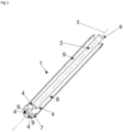
- Fig. 1 shows a holding device 1 for receiving at least one temperature sensor 2 (not shown, see Fig. 5 to 9 ).
- the holding device shown consists of an elongated base body segment 3, which is inserted into an immersion tube 15 (see also Fig. 5 to 9 ) can be introduced.
- the base body segment 3 has a total of four essentially straight, ie unbent, longitudinal grooves 4, which run parallel to the longitudinal axis 5 of the base body segment 3 from a lower end 6 to an upper end 7 of the base body segment 3.
- one of the four longitudinal grooves 4 is designed as a longitudinal holding groove 8, which can accommodate a temperature sensor 2.
- the remaining three longitudinal grooves 4 are referred to as further longitudinal holding grooves 9 and are designed to accommodate cables from temperature sensors 2 of further base body segments.
- temperature sensors 2 in particular the temperature sensor heads 27, are adjacent to the lower 6 or upper end 7 of the base body segment 3 in the longitudinal holding groove 8 arranged and are accommodated there in a positive and/or frictional manner.
- the base body segment 3 has a substantially cylindrical shape - except for the longitudinal grooves 4 - and is designed as a solid part without cavities.
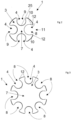
- Fig. 2 shows a view of the upper end 7 of the base body segment 3 according to FIG Fig. 1 embodiment shown. It can be seen that both the longitudinal holding groove 8 and the further longitudinal holding grooves 9 have an at least partially round edge 25 when viewed in cross section. Furthermore, it can be seen that the longitudinal grooves 4 (i.e. the holding longitudinal groove 8 and the further holding longitudinal grooves 9) are arranged at a regular distance from one another along the outer circumference of the base body segment 3. In the embodiment shown, the longitudinal holding groove 8 has a larger cross section than the other longitudinal holding grooves 9. The cross section of the longitudinal holding groove 8 can be adapted to a cross section of a temperature sensor 2.
- the cross section of the longitudinal holding groove 8 and the cross sections of the further longitudinal holding grooves 9 are essentially identical or that several longitudinal holding grooves 8 are provided on the base body segment 3.
- a temperature sensor 2 can be inserted into each of the longitudinal grooves 4.
- the cross sections of the further longitudinal holding grooves 9 are smaller than the cross section of the longitudinal holding groove 8, so that temperature sensors 2 cannot be inserted into the further longitudinal holding grooves 9 (but only into the longitudinal holding groove 8).
- the longitudinal holding groove 8 forms a clamping lug 12 on the longitudinal edges 10 delimiting the opening 11. The clamping lugs 12 prevent an inserted temperature sensor 2 from being accidentally released from the longitudinal holding groove 8.
- the clamping lugs 12 hold the temperature sensor 2 in the longitudinal holding groove 8 in a form-fitting and/or frictional manner.
- the frictional or positive fit ensures that the temperature sensor 2 is held in the intended location and cannot accidentally fall out of the longitudinal holding groove 8 or slip in the axial direction.
- the other longitudinal holding grooves 9 can also form clamping lugs.
- the temperature sensor 2 can be clipped into the longitudinal holding groove 8.
- the clamping lugs 12 become temporary pushed outwards. In principle, the temperature sensor 2 can be clipped in at any point along the longitudinal holding groove 8.
- Fig 3 shows an alternative embodiment of the base body segment 3 with a total of eight longitudinal grooves 4.
- the longitudinal grooves 4 all have the same cross section and are designed as holding longitudinal grooves 8, so that a temperature sensor 2 can be inserted into each of the longitudinal grooves 4.
- one or more of the longitudinal grooves 4 are designed as a longitudinal holding groove 8 and the remaining longitudinal grooves 4 are designed as further longitudinal holding grooves 9 with a smaller cross section.
- Fig. 4 shows a holding device 1 with two similar basic body segments 3 and 3 '. Additional base body segments could also be added.
- Each of the base body segments 3, 3' has a longitudinal holding groove 8, 8' and three further longitudinal holding grooves 9, 9' with a reduced cross section compared to the longitudinal holding groove 8, 8'.
- the base body segments 3, 3' are joined together in such a way that the longitudinal grooves 4, 4' merge into one another in alignment.
- the base body segments 3, 3' are oriented in such a way that the longitudinal holding groove 8 of the base body segment 3 is arranged in alignment with a further longitudinal holding groove 9' of the base body segment 3'.
- the further longitudinal holding grooves 9, 9' have a smaller cross section than the longitudinal holding groove 8, 8'.
- a temperature sensor 2, 2' is inserted into each longitudinal holding groove 8, 8 'of a base body segment 3, 3'.
- the cable 13 of the temperature sensor 2 for example, initially runs in the longitudinal holding groove 8 of the base body segment 3 and is then guided in one of the further longitudinal holding grooves 9 'of the base body segment 3'.
- the cable 13' of the temperature sensor 2' is also initially guided in the longitudinal holding groove 8' of the base body segment 3'. If another base body segment 3" were attached to the base body segment 3', the cables 13, 13' could each be continued in a further longitudinal holding groove 9" of this base body segment 3".
- the principle can be expanded as required. It is expedient if the number of longitudinal grooves 4 corresponds at least to the number of temperature sensors 2 of the holding device 1. In the embodiment according to Fig. 4 A distinction is made between longitudinal holding grooves 8 and further longitudinal holding grooves 9. In an alternative embodiment, it can also be provided that all longitudinal grooves 4 of each base body segment 3, 3 ', 3'' etc. are designed as similar longitudinal holding grooves 8, ie no further longitudinal holding grooves 9 are provided.
- Fig. 5A shows, with a view to the upper end 7, a base body segment 3 with a longitudinal holding groove 8 and three further longitudinal holding grooves 9, a temperature sensor 2 being inserted into the longitudinal holding groove 8.
- the further longitudinal holding grooves 9 of the base body segment 3 are unoccupied within the course of the base body segment 3 and therefore partially allow a view of temperature sensor heads 27 ', 27 "and 27''', which are in the longitudinal holding grooves 8', 8" and 8''' from on Base body segment 3 in the longitudinal direction attached base body segments 3', 3" and 3' are inserted. It can be seen that the temperature sensor heads 27', 27" and 27' are partially covered by the further longitudinal holding grooves 9 of the base body segment 3.
- the positions of the temperature sensor heads 27', 27" and 27''' are indicated by dashed lines.
- the sensor cables 13, 13', 13" and 13'' are not visible in this view, but run as shown in Fig. 4 principle shown.
- the temperature sensor 2 more precisely the temperature sensor head 27, protrudes from the opening 11 of the longitudinal holding groove 8 and comes into frictional contact with an inner wall 14 of an immersion tube 15.
- the base body segment is in no contact with the inner wall 14 of the immersion tube 15. This is in the Detail view Fig. 5B visible.
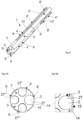
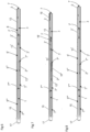
- Fig. 6 shows a schematic representation of a dip tube 15 shown in half section with several base body segments 3, 3 ', 3'', 3' arranged therein.
- a connecting flange 17 is provided at the lower end of the dip tube 15.
- the Basic body segments 3, 3', 3'', 3' are according to the scheme of Fig. 4 inserted into the dip tube 15.
- a temperature sensor 2, 2', 2", 2" is accommodated in each base body segment 3, 3', 3", 3".
- the cable 13 of the temperature sensor 2 is arranged at the opposite end of the connecting flange 17
- Base body segment 3 first runs in the longitudinal holding groove 8 of the base body segment 3 and is then guided in the further longitudinal holding grooves 9 ', 9'', 9′′′ of the remaining base body segments 3', 3'', 3′′′ up to the connecting flange 17.
- the Cable 13' and 13" of the temperature sensors 2' and 2" are routed to the connection flange 17.
- the cable 13′′′ of the temperature sensor 2′′′ in the base body segment 3′′′ is only routed in the longitudinal holding groove 8′′′ up to the connection flange 17.
- the temperature sensors 2, 2' , 2", 2" or their sensor heads are flush with the upper end 7, 7', 7", 7" of the respective base body segment 3, 3', 3", 3" opposite the connecting flange 17.
- Fig. 7 also shows a schematic representation of a dip tube 15 shown in half section with several base body segments 3, 3 ', 3'', 3''' arranged therein.
- positioning elements 18 are used to position the temperature sensors 2.
- the positioning elements 18, 18', 18", 18" close flush with the upper end 7, 7', 7'', 7''' of the respective base body segment 3, 3', 3", 3, which is opposite the connecting flange 17 ''' away.
- Fig. 8 also shows a schematic representation of a dip tube 15 shown in half section with several base body segments 3, 3 ', 3'', 3''' arranged therein.
- base body segments 3, 3', 3'', 3' of different lengths are used here.
- the temperature sensors 2, 2′, 2′′, 2′′′ or their sensor heads close again flush with the upper end 7, 7′, 7′′, 7′′′ of the respective base body segment 3, 3′, 3, which is opposite the connecting flange 17 '', 3′′′ from. Due to the different lengths of the base body segments, the temperature sensors 2, 2 ', 2'', 2′′′ or their sensor heads are located compared to the embodiment of Fig. 6 in another position.
- Fig. 9A also shows a schematic representation of a dip tube 15 (shown in half section) with a base body segment 3 arranged therein.
- the base body segment 3 has a plurality of similar, parallel holding longitudinal grooves 8, which are arranged at regular intervals from one another along the outer circumference of the base body segment 3.
- a temperature sensor 2 is inserted into each of the longitudinal holding grooves 8.
- the temperature sensor heads of the temperature sensors 2 are flush with the end face at the upper end 7 of the base body segment 3.
- the cables 13 of the temperature sensors 2 run in the respective longitudinal holding groove 8 to the connecting flange 17.
- Fig. 9B also shows a schematic representation of a dip tube 15 shown in half section with a base body segment 3 arranged therein.
- the base body segment 3 has, as in Fig. 9 executed, several similar, parallel holding longitudinal grooves 8, which are arranged at regular intervals from one another along the outer circumference of the base body segment 3.
- a temperature sensor 2 is inserted into each of the longitudinal holding grooves 8.
- the temperature sensors 2 are placed at different heights by means of positioning elements 18, which in turn are flush with the upper end 7 of the base body segment 3 opposite the connecting flange 17.
- the positioning elements 18 can have different lengths.
- the cables 13 of the temperature sensors 2 run in the longitudinal holding groove 8.
- Fig. 10A shows a hot water tank 19, in the receiving space 20 of which a temperature measuring device 21 in the form of a dip tube 15 with at least one holding device 1 and at least one temperature sensor 2 is arranged vertically. If there is a liquid in the receiving space 20, the temperature of the liquid can be determined using the temperature sensor 2. If several temperature sensors 2 are arranged in the immersion tube 15, the temperature of the liquid can be different heights can be determined. Alternatively, it can also be provided that the dip tube 15 is arranged horizontally in the receiving space 19 (cf. Fig. 10B ).
Landscapes
- Engineering & Computer Science (AREA)
- Physics & Mathematics (AREA)
- Chemical & Material Sciences (AREA)
- Combustion & Propulsion (AREA)
- Mechanical Engineering (AREA)
- General Engineering & Computer Science (AREA)
- Thermal Sciences (AREA)
- General Physics & Mathematics (AREA)
- Measuring Temperature Or Quantity Of Heat (AREA)
Applications Claiming Priority (2)
| Application Number | Priority Date | Filing Date | Title |
|---|---|---|---|
| ATA51157/2019A AT523312B1 (de) | 2019-12-27 | 2019-12-27 | Haltevorrichtung für einen Temperaturfühler, Tauchrohr mit einer solchen Haltevorrichtung sowie Vorrichtung mit einem solchen Tauchrohr |
| EP20216777.1A EP3842774B8 (fr) | 2019-12-27 | 2020-12-23 | Dispositif de maintien pour une sonde de température, tube d'immersion doté d'un tel dispositif de maintien ainsi que dispositif doté d'un tel tube d'immersion |
Related Parent Applications (2)
| Application Number | Title | Priority Date | Filing Date |
|---|---|---|---|
| EP20216777.1A Division-Into EP3842774B8 (fr) | 2019-12-27 | 2020-12-23 | Dispositif de maintien pour une sonde de température, tube d'immersion doté d'un tel dispositif de maintien ainsi que dispositif doté d'un tel tube d'immersion |
| EP20216777.1A Division EP3842774B8 (fr) | 2019-12-27 | 2020-12-23 | Dispositif de maintien pour une sonde de température, tube d'immersion doté d'un tel dispositif de maintien ainsi que dispositif doté d'un tel tube d'immersion |
Publications (2)
| Publication Number | Publication Date |
|---|---|
| EP4332527A2 true EP4332527A2 (fr) | 2024-03-06 |
| EP4332527A3 EP4332527A3 (fr) | 2024-05-22 |
Family
ID=73856956
Family Applications (2)
| Application Number | Title | Priority Date | Filing Date |
|---|---|---|---|
| EP20216777.1A Active EP3842774B8 (fr) | 2019-12-27 | 2020-12-23 | Dispositif de maintien pour une sonde de température, tube d'immersion doté d'un tel dispositif de maintien ainsi que dispositif doté d'un tel tube d'immersion |
| EP23215969.9A Pending EP4332527A3 (fr) | 2019-12-27 | 2020-12-23 | Dispositif comprenant un compartiment pour contenir un liquide |
Family Applications Before (1)
| Application Number | Title | Priority Date | Filing Date |
|---|---|---|---|
| EP20216777.1A Active EP3842774B8 (fr) | 2019-12-27 | 2020-12-23 | Dispositif de maintien pour une sonde de température, tube d'immersion doté d'un tel dispositif de maintien ainsi que dispositif doté d'un tel tube d'immersion |
Country Status (2)
| Country | Link |
|---|---|
| EP (2) | EP3842774B8 (fr) |
| AT (1) | AT523312B1 (fr) |
Families Citing this family (2)
| Publication number | Priority date | Publication date | Assignee | Title |
|---|---|---|---|---|
| SI26368A (sl) * | 2022-06-16 | 2023-12-29 | Gorenje, d.o.o. | Razporeditev tipala v pečici |
| FR3159436B1 (fr) | 2024-02-21 | 2026-01-16 | Viessmann Climate Solutions Se | Dispositif support pour capteur, dispositif de mesure ou de suivi de température pour contenant à liquide et contenant les comprenant |
Citations (5)
| Publication number | Priority date | Publication date | Assignee | Title |
|---|---|---|---|---|
| DE1473158A1 (de) | 1963-08-19 | 1968-10-24 | Greene Norman D | Verfahren und Vorrichtung zum Messen von Stroemungsverhaeltnissen sowie Verfahren zum Herstellen der Messvorrichtung |
| DE1648217A1 (de) | 1966-09-06 | 1971-05-27 | Gen Electric | Temperaturmessfuehler |
| DE8631832U1 (de) | 1986-11-27 | 1987-02-19 | Viessmann Werke Kg, 3559 Allendorf | Tauchhülse mit Fühler |
| DE29706390U1 (de) | 1997-04-10 | 1997-05-22 | Buderus Heiztechnik Gmbh, 35576 Wetzlar | Halter für einen Temperaturfühler |
| DE202007017515U1 (de) | 2007-12-15 | 2009-04-16 | Robert Bosch Gmbh | Fixiervorrichtung für Temperaturfühler in einer Tauchhülse |
Family Cites Families (7)
| Publication number | Priority date | Publication date | Assignee | Title |
|---|---|---|---|---|
| CH690381A5 (de) * | 1996-03-14 | 2000-08-15 | Etheco Europ Thermostat Compan | Anordnung mit einem Schutzrohr zur Messung mindestens einer Temperatur, wobei im Schutzrohr ein oder mehrere parallele, längliche Temperaturfühler angeordnet sind. |
| DE29820671U1 (de) * | 1998-11-19 | 1999-02-18 | Stiebel Eltron Gmbh & Co Kg, 37603 Holzminden | Halter für einen Temperaturfühler |
| DE202006018576U1 (de) * | 2006-12-06 | 2008-04-17 | Günther Heisskanaltechnik Gmbh | Heisskanaldüse mit Temperaturfühler |
| JP4539777B2 (ja) * | 2008-02-01 | 2010-09-08 | ダイキン工業株式会社 | 貯湯式給湯機および貯湯式暖房給湯機 |
| DE102009001557A1 (de) * | 2009-03-13 | 2010-09-23 | BSH Bosch und Siemens Hausgeräte GmbH | Warmwasserspeicher mit Sensorsystem |
| CA2813250C (fr) * | 2010-10-01 | 2019-09-24 | Afl Telecommunications Llc | Cable de detection |
| JP2015075460A (ja) * | 2013-10-11 | 2015-04-20 | 三菱重工業株式会社 | 状態量の検出装置及び検出方法 |
-
2019
- 2019-12-27 AT ATA51157/2019A patent/AT523312B1/de active
-
2020
- 2020-12-23 EP EP20216777.1A patent/EP3842774B8/fr active Active
- 2020-12-23 EP EP23215969.9A patent/EP4332527A3/fr active Pending
Patent Citations (5)
| Publication number | Priority date | Publication date | Assignee | Title |
|---|---|---|---|---|
| DE1473158A1 (de) | 1963-08-19 | 1968-10-24 | Greene Norman D | Verfahren und Vorrichtung zum Messen von Stroemungsverhaeltnissen sowie Verfahren zum Herstellen der Messvorrichtung |
| DE1648217A1 (de) | 1966-09-06 | 1971-05-27 | Gen Electric | Temperaturmessfuehler |
| DE8631832U1 (de) | 1986-11-27 | 1987-02-19 | Viessmann Werke Kg, 3559 Allendorf | Tauchhülse mit Fühler |
| DE29706390U1 (de) | 1997-04-10 | 1997-05-22 | Buderus Heiztechnik Gmbh, 35576 Wetzlar | Halter für einen Temperaturfühler |
| DE202007017515U1 (de) | 2007-12-15 | 2009-04-16 | Robert Bosch Gmbh | Fixiervorrichtung für Temperaturfühler in einer Tauchhülse |
Also Published As
| Publication number | Publication date |
|---|---|
| EP3842774B8 (fr) | 2024-03-27 |
| EP4332527A3 (fr) | 2024-05-22 |
| AT523312B1 (de) | 2022-12-15 |
| EP3842774A1 (fr) | 2021-06-30 |
| EP3842774C0 (fr) | 2024-01-24 |
| AT523312A1 (de) | 2021-07-15 |
| EP3842774B1 (fr) | 2024-01-24 |
Similar Documents
| Publication | Publication Date | Title |
|---|---|---|
| DE102007016822A1 (de) | Gestängekupplung mit Zapfen | |
| DE102007037684A1 (de) | Positionierungsvorrichtung für eine stabförmige Messeinrichtung | |
| EP3842774B1 (fr) | Dispositif de maintien pour une sonde de température, tube d'immersion doté d'un tel dispositif de maintien ainsi que dispositif doté d'un tel tube d'immersion | |
| DE68907211T2 (de) | Markierungsanordnung. | |
| DE1925171A1 (de) | Verbindungsvorrichtung oder Kupplung | |
| DE102015116421A1 (de) | Kippdübel | |
| EP3422901B1 (fr) | Procédé de fabrication d'une coulisse | |
| DE102015006216A1 (de) | Verbindungsvorrichtung zum elektrischen Verbinden einer elektrischen Maschine mit einer Leistungselektronik | |
| DE2930833C3 (de) | Klemmuffe | |
| DE202007004065U1 (de) | Vorrichtung zur Anbringung einer Markierung an Rohrenden | |
| DE102014221578A1 (de) | Anordnung zur verdrehsicheren Befestigung eines Kabelschuhs eines Kabels an einer Klemmplatte | |
| DE102013101491A1 (de) | Höheneinstellbare Rundstangenführung | |
| DE8329408U1 (de) | Befestigungsvorrichtung fuer sensoren | |
| DE102012003817A1 (de) | Bauteilverbinder zum Verbinden von zylindrischen Bauteilen | |
| DE202016104763U1 (de) | Fahrradpedal mit einfach montierbarem Dorn | |
| DE102016101941A1 (de) | Armatur für Gas- oder Wasserrohre | |
| DE202018005969U1 (de) | Schraubeneinführhilfe und Set aus Schraubeneinführhilfe und Schraube | |
| EP3258171B1 (fr) | Système d'assemblage de deux tuyaux d'échappement insérés partiellement l'un dans l'autre | |
| EP3079214A2 (fr) | Bouchon de fermeture pour passe-cables ou tube de pose de cables | |
| DE202005020788U1 (de) | Marknagel aus Metall | |
| DE102016202654B4 (de) | Kupplungseinrichtung, umfassend zwei Bauteile, die mittels eines Bajonett-Verschlusses lösbar miteinander verbunden sind | |
| DE102016214938A1 (de) | Steckmutter | |
| DE102013018439A1 (de) | Vorrichtung zum Montieren einer Stütz- und Dehnmuffe für Rohrleitungen | |
| DE102025114659A1 (de) | Rohrabschnitt eines Messrohrs in einer verfahrenstechnischen Prozessanlage für Hygieneanwendungen und Anordnung in einer solchen Prozessanlage | |
| DE102016003692A1 (de) | Führungselement zum Führen wenigstens eines in einem Fahrzeug zu verbauenden Leitungselements, sowie Fahrzeug mit einem solchen Führungselement |
Legal Events
| Date | Code | Title | Description |
|---|---|---|---|
| PUAI | Public reference made under article 153(3) epc to a published international application that has entered the european phase |
Free format text: ORIGINAL CODE: 0009012 |
|
| STAA | Information on the status of an ep patent application or granted ep patent |
Free format text: STATUS: THE APPLICATION HAS BEEN PUBLISHED |
|
| AC | Divisional application: reference to earlier application |
Ref document number: 3842774 Country of ref document: EP Kind code of ref document: P |
|
| AK | Designated contracting states |
Kind code of ref document: A2 Designated state(s): AL AT BE BG CH CY CZ DE DK EE ES FI FR GB GR HR HU IE IS IT LI LT LU LV MC MK MT NL NO PL PT RO RS SE SI SK SM TR |
|
| REG | Reference to a national code |
Ref country code: DE Ref legal event code: R079 Free format text: PREVIOUS MAIN CLASS: G01K0013020000 Ipc: G01K0001140000 |
|
| PUAL | Search report despatched |
Free format text: ORIGINAL CODE: 0009013 |
|
| AK | Designated contracting states |
Kind code of ref document: A3 Designated state(s): AL AT BE BG CH CY CZ DE DK EE ES FI FR GB GR HR HU IE IS IT LI LT LU LV MC MK MT NL NO PL PT RO RS SE SI SK SM TR |
|
| RIC1 | Information provided on ipc code assigned before grant |
Ipc: G01K 13/02 20210101ALI20240417BHEP Ipc: G01K 1/14 20210101AFI20240417BHEP |
|
| STAA | Information on the status of an ep patent application or granted ep patent |
Free format text: STATUS: REQUEST FOR EXAMINATION WAS MADE |
|
| 17P | Request for examination filed |
Effective date: 20240705 |
|
| RBV | Designated contracting states (corrected) |
Designated state(s): AL AT BE BG CH CY CZ DE DK EE ES FI FR GB GR HR HU IE IS IT LI LT LU LV MC MK MT NL NO PL PT RO RS SE SI SK SM TR |
|
| STAA | Information on the status of an ep patent application or granted ep patent |
Free format text: STATUS: EXAMINATION IS IN PROGRESS |
|
| 17Q | First examination report despatched |
Effective date: 20251027 |