EP4332536A1 - Dispositif de vérification d'une liaison d'une bande de garantie et/ou d'au moins un moyen de raccordement d'un couvercle de fermeture doté d'un corps de base de couvercle et de vérification d'une étanchéité du corps de base de couvercle - Google Patents
Dispositif de vérification d'une liaison d'une bande de garantie et/ou d'au moins un moyen de raccordement d'un couvercle de fermeture doté d'un corps de base de couvercle et de vérification d'une étanchéité du corps de base de couvercle Download PDFInfo
- Publication number
- EP4332536A1 EP4332536A1 EP22193757.6A EP22193757A EP4332536A1 EP 4332536 A1 EP4332536 A1 EP 4332536A1 EP 22193757 A EP22193757 A EP 22193757A EP 4332536 A1 EP4332536 A1 EP 4332536A1
- Authority
- EP
- European Patent Office
- Prior art keywords
- base body
- lid base
- lid
- guarantee band
- testing
- Prior art date
- Legal status (The legal status is an assumption and is not a legal conclusion. Google has not performed a legal analysis and makes no representation as to the accuracy of the status listed.)
- Granted
Links
Images


Classifications
-
- G—PHYSICS
- G01—MEASURING; TESTING
- G01M—TESTING STATIC OR DYNAMIC BALANCE OF MACHINES OR STRUCTURES; TESTING OF STRUCTURES OR APPARATUS, NOT OTHERWISE PROVIDED FOR
- G01M3/00—Investigating fluid-tightness of structures
- G01M3/02—Investigating fluid-tightness of structures by using fluid or vacuum
- G01M3/26—Investigating fluid-tightness of structures by using fluid or vacuum by measuring rate of loss or gain of fluid, e.g. by pressure-responsive devices, by flow detectors
-
- G—PHYSICS
- G01—MEASURING; TESTING
- G01M—TESTING STATIC OR DYNAMIC BALANCE OF MACHINES OR STRUCTURES; TESTING OF STRUCTURES OR APPARATUS, NOT OTHERWISE PROVIDED FOR
- G01M99/00—Subject matter not provided for in other groups of this subclass
- G01M99/007—Subject matter not provided for in other groups of this subclass by applying a load, e.g. for resistance or wear testing
Definitions
- the invention relates to a device for testing a connection of a guarantee band and/or at least one connection means of a closure lid with a lid base body and for testing a tightness of the lid base body, comprising a driving element for gripping the guarantee band and/or the at least one connection means, a contact element for the lid base body , wherein the driving element and the contact element are movable relative to one another in an interaction direction in such a way that a tear-off force can be exerted on connecting elements between the lid base body and the guarantee band and/or the binding means and a force measuring device for measuring the tear-off force during the relative movement between the guarantee band and/or the binding means and the lid base body.
- the invention further relates to a system for cutting a guarantee band and/or at least one connection means of a closure lid and a method for testing a connection of a guarantee band and/or at least one connection means of a closure lid with a lid base body and for testing a tightness of the lid base body.
- closure lids e.g. B. bottle caps with lids made of plastic or sheet metal, with guarantee bands and / or with binding means. Guarantee tapes are used to ensure originality and ensure that it is immediately recognizable if the sealing lid has been removed after a container has been filled for the first time has since been removed and reinstalled. This could be an indication of replacement or contamination of the container contents and indicates to the user that they should not use the container contents - for example, not consume food.
- Guarantee bands are arranged over a weakening line on a base body of the closure lid.
- the guarantee band interacts with a counterpart on the container in such a way that it is torn off from the lid base body and/or severed along its circumference.
- the sealing cover has been (temporarily) removed.
- Known guarantee bands are attached to the lid base body via a plurality of connecting elements (e.g. webs or bridges), the base body, the connecting elements and the ring being formed in one piece. They further include a circumferential bead-like projection on the container, which holds back the guarantee band when the lid is removed.
- the weakening line can be introduced during the shaping of the lid or only in a subsequent cut, e.g. B. by introducing suitable slots.
- Tethers ensure that the closure lid remains attached to the container even after it has been opened and removed. This prevents the cap from being lost or carelessly thrown away, which leads to unwanted waste.
- the connecting means generally run between a ring that remains on the container (e.g. on the bottle neck), in particular the guarantee ring, and the base body of the closure lid. They are designed like a band and are created when the closure lid is opened due to a suitable slot geometry on the closure lid. There are known binding agents with a single such compound and those with multiple compounds.
- the guarantee bands meet the requirements (e.g. with regard to a removal or force required for tearing or production).
- covers are randomly taken from production and checked.
- the test was usually carried out manually or with manually operated, specially equipped tension-strain measuring devices, whereby the tear-off force was measured using a force sensor and the force required for tearing off (or tearing open) was determined. If this force is outside a specified range (which depends, among other things, on the type of container and the material as well as the geometry of the lid), there is an error in the manufacturing process that must be corrected, e.g. B. by adjusting operating parameters and/or exchanging tools.
- the present applicant describes a device for checking a connection of a guarantee band of a tamper-evident device of a closure lid with a lid base body, comprising a driving element for gripping the guarantee band, a stop element for the lid base body, wherein the driving element and the stop element are movable relative to one another in such a way that a tear-off force is applied the guarantee band can be exercised, a force measuring device for measuring the tear-off force during the relative movement of the guarantee band and the lid base body and a separating device for cutting the guarantee band after it has been torn off from the lid base body.
- closure lids must meet additional requirements. Another property required of closure lids is tightness. On the one hand, the escape of gases, especially carbon dioxide in carbonated drinks, should be prevented; on the other hand, the penetration of gases from the environment is also undesirable. Specific devices are available for leak testing.
- the object of the invention is to create a device belonging to the technical field mentioned at the outset, which simplifies the testing of closure lids.
- the device has a sealing stamp with a sealing structure, so that a sealed chamber can be formed between the contact element and the lid base body.
- the device further comprises a device for setting a predetermined gas pressure in the chamber and a device for detecting a gas exit from the chamber and/or a gas entry into the chamber.
- the driving element and the sealing stamp are arranged together on a carrier that is movable in the interaction direction and spaced perpendicularly to the interaction direction.
- the sealing stamp interacts with the inside of the lid, namely with the bottom of the lid base body and/or with its jacket. In particular, it interacts with corresponding sealing lips to seal the closure lid from the bottle neck.
- the sealing structure is arranged in particular on the front side of the sealing stamp. It interacts with the inside of the closure lid to achieve sealing of the chamber.
- the sealing structure is a structure running around the front or casing with a constant profile.
- the sealing structure can be formed by a material portion of the sealing stamp, i.e. in one piece with it, or by a separate element that is arranged on the sealing stamp.
- the distance between the centers of the driving element and the sealing stamp perpendicular to the direction of interaction exceeds in particular the diameter of the closure lid to be tested, so that in a first position of the closure lid its tightness is tested with the help of the sealing stamp and in a second, in particular subsequent, position the tear-off force is tested by means of the driving element can be done without hindering the other element.
- a tear-off force is understood here as a force that attacks the guarantee band or the binding means and acts in such a direction that - at one sufficient value (the "force required to tear off") - the guarantee band or the binding means or an element thereof is torn off from the lid base body and / or torn open along its circumference.
- this is a force in which a bridge connection between the base body and the guarantee ring or a connection of the connecting means between the base body and the ring breaks.
- the measurement of the tear-off force preferably includes recording a force-time or force-distance curve at least up to the tear-off point.
- the device according to the invention can be used to test both the tightness of a closure lid and the properties of its guarantee band and/or binding means. However, it can only be used for leak testing or testing the properties of the strap/binding means in relation to an individual closure cap or an entire lot. Both modalities do not necessarily have to be tested in every case, but the test steps “tightness”, “guarantee band” and/or “binding means” can preferably be activated and deactivated selectively.
- the device according to the invention enables the - in particular automatic - measurement of both the tightness and the properties of guarantee bands and / or binding means. Because the driving element and the sealing stamp are arranged together on a carrier, only a single drive is necessary for the corresponding movement of both elements. whereby the design effort for the device is reduced.
- the contact element is preferably arranged in a stationary manner.
- the driving element and the sealing stamp are moved so that the required relative movement to the contact element results.
- the contact element is formed on the end face of a mandrel, and the driving element is linearly movable relative to the mandrel along the interaction direction.
- the mandrel is particularly stationary and the driving element is designed to be movable.
- the mandrel has - at least in the area of contact with the closure lid - in particular the geometry of a straight circular cylinder, with the diameter being slightly smaller than the inner diameter of the closure lid.
- the front surface of the mandrel is designed in such a way that it can interact with the lid base body over a large area.
- the bottom or another part of the lid base body interacts with the front surface on the inside of the lid and defines the axial position of the lid base body.
- the driving element can be a bead-like structure, which essentially corresponds to the structure on the container with which the closure lid is intended to interact.
- the driving element can also be provided by several spaced-apart structures, e.g. B. cams can be formed.
- the closure lid with the attached guarantee band or binding means and the driving element are positioned relative to one another before the tear-off force is measured in such a way that the guarantee band or binding means at least touches the driving element partially intervened.
- the closure cover with a guarantee band or binding means can be pushed over the driving element or the driving element can be pushed into the closure cover.
- Driving elements with variable shapes e.g. B. with radially movable claws, can be inserted into the interior of the lid and are only then spread.
- gripping elements e.g. B. with pliers-like clamping mechanisms, which grip the guarantee band all around or at spaced points.
- the driving element is designed in particular as a sleeve which is guided coaxially with respect to the mandrel. In this way, a constant, uniform interaction is achieved between the driving element and the guarantee band or binding means.
- the coaxial arrangement of the mandrel and the sleeve-shaped driving element also enables a stable and simple storage of the driving element and a defined further movement of the separated guarantee band, in that it is guided further by the mandrel and initially remains threaded on it.
- a longitudinal direction of the mandrel has an angle of at least 30° to a horizontal plane, the movement for measuring the tear-off force taking place upwards and the device comprising a collecting device for the lid base body and the torn off guarantee band.
- the lid base and the guarantee band can be conveyed away from the mandrel using gravity. Additional funding in the immediate vicinity of the mandrel (such as suction devices or magnets when processing closure lids made of ferromagnetic materials) is unnecessary.
- the collecting device ensures that the base bodies and belts falling down from the mandrel are safely caught for transport. Instead of gravity or to support it - as explained below - compressed air can be used to blow off the base body in particular.
- the collecting device advantageously has a collecting surface that is inclined in the collecting position, so that the collected lid base body and the collected guarantee band are automatically further conveyed due to gravity. This means that separate funding that interacts with the collecting device can be avoided.
- the longitudinal direction of the mandrel has an inclination of 10-80° to the horizontal plane, and the collecting surface of the collecting device is perpendicular to the longitudinal direction of the mandrel in the collecting position.
- the oblique arrangement of the mandrel and the collecting surface of the collecting device enables a particularly simple construction, in which in particular a unit which includes the mandrel and the bearing of the collecting device can be installed inclined to a horizontal.
- the inclined arrangement also makes it possible for the feed direction for the closure caps in the longitudinal direction of the mandrel and the discharge direction for the base bodies and guarantee bands, which is directed vertically downwards due to gravity, to be different. Possible conflicts between the supply and the discharge can be constructively minimized.
- An inclined arrangement can also be advantageous for the support for the lid base body, especially if this serves to provide the closure lid to be tested.
- the lid can be conveyed onto the support with the help of gravity (e.g. against stops as positioning devices), so that structurally complex conveying devices in the area of the support are avoided.
- an entire assembly of the device with feed, mandrel and discharge is arranged obliquely as a whole. In this way, the design effort can be minimized.
- a vertical or almost vertical arrangement of the mandrel is also possible:
- the material to be removed can be transported away from the feed path for the closure lids, for example with the help of a blow-out device, and by cutting the guarantee band into a sufficient number of parts (e.g. at least 2 or 3 parts) can be ensured that the band does not remain on the mandrel, but falls onto the collecting device due to gravity.
- a horizontal arrangement of the mandrel or an inclined arrangement with an angle of less than 10° is also possible possible. In this case, it may make sense to provide a separate device for releasing the lid base body from the mandrel, e.g. B.
- a mechanical ejection mechanism mounted in the mandrel or an outlet for compressed air opening into the face of the mandrel.
- the guarantee band is cut in several places so that all parts can be safely removed from the mandrel.
- a limiting device is preferably present which can be selectively moved, in particular pivoted, into an area in front of a free end of the contact element. Accordingly, in the context of the method according to the invention, after the lid base body has been gripped by the driving element, a limiting device is advantageously moved into an area in front of a free end of the contact element, in particular pivoted in.
- the limiting device prevents the lid base body from tilting when forces are exerted on one side by the driving element. It is moved accordingly, in particular into the area mentioned, before a connection means of the closure cover can be torn off. Instead of a pivoting movement, the limiting device can also be moved into the area in front of the free end of the contact element and out of it with a linear movement, in particular in a direction perpendicular to the interaction direction.
- the limiting device is preferably designed as a plate which has a flat surface facing the contact element in a plane perpendicular to the interaction direction. The distance of this surface from the end face of the contact element is in particular a maximum of a third, preferably a maximum of a sixth, of the outside diameter of the cover base body.
- the collecting device and the limiting device can advantageously be pivoted about the same pivot axis. This enables a particularly simple and compact design, whereby elements of the pivot axis can be used for both the collecting device and the limiting device.
- the device advantageously comprises a selectively activatable stop for the lid base body, which is arranged in a feed for the lid base body is that the lid base body is positioned in a first position when the stop is activated, in which the sealing stamp can interact with the lid base body to form the sealed chamber.
- the stop can, for example, be activated pneumatically and comprise elements which can be selectively moved into and out of a feed path for the lid base body, e.g. B. laterally, in a horizontal direction, or vertically up and/or down.
- the lid base body may be arranged in the feed for the lid base body in such a way that it positions the lid base body in a second position in which the driving element can grip the guarantee band.
- the second stop can be arranged fixedly on the device, but its position is preferably at least manually adjustable, so that the device can be easily adapted to different outer diameters of the closure lid.
- the device for detecting the gas exit or entry preferably comprises a pressure measuring device for measuring a chamber pressure.
- This device can measure the pressure in particular on the inlet side. With their help, it can first be ensured that a predetermined desired overpressure or negative pressure is generated in the chamber, then the chamber is isolated from the compressed air source together with a pressure sensor of the pressure measuring device and the pressure drop or increase in pressure is recorded during a predetermined time (or until it is reached). a predetermined value). The tightness can therefore be quantified directly. If the residual pressure is sufficiently high after the specified time, i.e. the pressure drop is sufficiently low, the sealing lid has passed the leak test. (Similarly, it can be assumed that the test has been passed if a certain minimum time has elapsed until the specified residual pressure is reached.)
- the compressed gas reservoir in which the predetermined pressure prevails, can remain connected to the chamber via a bypass line with a small cross-section after the supply line has been disconnected, with a flow measurement being carried out in the bypass is carried out, e.g. B. with the help of a calorimetric flow sensor.
- the flow indicates that air must flow in to maintain the chamber pressure, whereby the amount of air flowing in is in turn a measure of the (leaking) tightness.
- the device for detecting the gas exit or entry comprises a sniffer probe instead of or in addition to the pressure measuring device.
- a suitable test gas e.g. a mixture of nitrogen and hydrogen
- the device advantageously comprises a blow-out device for removing the lid base body and/or the guarantee band.
- the blow-out device can in particular comprise laterally directed air nozzles, so that the lid base body and/or the guarantee band can be moved laterally over the collecting device with a blast of air.
- the device advantageously comprises a separating device for cutting through the guarantee band after it has been torn off from the lid base body.
- Cutting the guarantee band leads to a considerable simplification of the removal of the guarantee band from the testing device, especially if the testing device is designed in such a way that the torn guarantee bands are threaded onto an element. Cutting through then enables removal, which does not necessarily have to take place axially along the element. In principle, an unlimited number of measurements can be carried out. This is in contrast to the case in which several guarantee rings initially remain threaded onto the element.
- Cutting makes sense not only when the guarantee band is torn off as a whole from the lid base body, but also when it is cut along the circumference during the opening process in such a way that sections remain that describe an angle of more than 180°.
- the separating device preferably comprises at least one cutting knife arranged in the peripheral region of the mandrel, which is designed in such a way that the guarantee band is severed by moving the cutting blade along the longitudinal direction of the mandrel.
- the guarantee band is mounted on the driving element, so that a safe cut is made when the cutting knife is advanced accordingly.
- the cutting knife can be arranged in a fixed manner relative to the mandrel; the necessary relative movement results from the axial movement of the driving element relative to the mandrel (and thus to the cutting knife).
- movable cutting knives or cutting disks or other types of cutting tools e.g. B. heated swords or laser tools are used.
- the cutting device preferably comprises at least two cutting knives, which are arranged in such a way that the guarantee band is cut at two circumferentially spaced locations.
- two cutting knives can be provided, which are arranged opposite one another (i.e. enclose an angle of 180°). It is also possible to use three or more cutting knives, which are preferably arranged evenly along the circumference.
- Two or more parts of the guarantee band resulting from cutting can be removed much more easily and reliably than a single (cut) band. If you cut into several parts, these can also be easily vacuumed off.
- a sleeve-shaped driving element advantageously has at least one groove in the longitudinal direction of the mandrel, which interacts with the at least one cutting knife.
- the groove on the outside of the driving element allows the cutting knife to easily pass through without the driving element or the cutting knife having to have moving parts. Compared to a multi-part driving element, the parts of which are each arranged between the cutting blades, the result is a simpler construction with improved stability.
- the device advantageously further comprises an evaluation unit for receiving measured values of the tear-off force measurements, for determining based on these measured values, whether the connection of the guarantee band and/or the at least one connecting means to the lid base body fulfills predetermined properties and to output the results of this determination.
- the evaluation unit also receives measured values from the device for detecting the gas exit or entry and processes these to determine whether the seal meets the requirements.
- the results can be output via an integrated output device.
- the result can be displayed optically on a screen and/or output acoustically via a loudspeaker.
- the output can also take place via an interface that can be connected to an output device, a device for further processing and/or storage of the information or to a machine control.
- the value of the tear-off force that led to the tearing or cutting of the guarantee band or the binding means is determined and output or forwarded. This is usually the maximum force value that was measured during a test process. (As a rule, the maximum force occurs before the actual tearing or cutting. Nevertheless, the maximum force is a suitable measure for assessing the correct formation of the connection between the guarantee band or binding means and the base body.)
- the evaluation unit can now also determine on the basis of several received measured values for the same connection whether one of several webs of the connection to the guarantee band and/or one element of several elements of the connecting means has a significantly reduced or increased tear-off force compared to other webs or elements having.
- several force values are determined and analyzed.
- the early or delayed tearing of a web or element is usually manifested by several (local) force maxima or a gradual drop in the measured force. If these are present and they have a certain minimum distance in the force-distance or force-time curve, it can be concluded that there is non-standard tearing and thus a possible production error.
- the multiple measured values received can be pre-processed before analysis, e.g. B. an averaging can take place, it can be a Standard deviation or derivative are calculated or other statistical calculations are made.
- the binding means are removed together with the guarantee band and/or with the lid base body, depending on where the tearing took place. It is also possible that the binding means tear in a central area, so that one part with the guarantee band and another part with the lid base body is removed.
- the device can be used fully automatically and, in particular, can be directly coupled to a system for producing closure lids with guarantee bands and/or binding means.
- closure caps are periodically removed (e.g. with the help of a blowing unit) and guided to the feed device of the device.
- a check can be carried out every minute or every 30 s (or even more frequently).
- up to 5 sealing lids per minute (or even more) can be tested both in terms of tightness and in terms of the connection quality of the guarantee ring and the connecting means.
- Traditional manual checks were often only carried out every half hour or even hourly. At a production rate of up to 3,500 lids per minute, the possible waste in the worst case was up to 210,000 closure lids.
- control device is designed in such a way that a processing parameter of the cutting device, in particular a temperature of a cutting knife of the cutting device, can be influenced depending on the transmitted results.
- the sharpness of the cutting knife which changes during operation due to wear
- the temperature of the cutting knife which can be influenced with the help of a controllable heater
- a loss of sharpness of the cutting knife can be compensated to a certain extent by increasing the temperature. If less deep or incomplete slots result due to a loss of sharpness, this leads to an increased tear-off force, which is necessary to separate or cut the guarantee band or to create the binding means. This is determined by the testing device and transmitted to the system's control device. The latter can then Turn up the heating of the cutting knife to increase the temperature of the cutting knife until satisfactory tear-off force values are achieved again. If the tear-off force of the binding means and/or the guarantee band is too small, this can indicate a wrong cut.
- a knife change or a regrinding process for the knife can be triggered when non-standard sealing lids are detected. These measures can be carried out automatically in the cutting device or manually.
- the delivery of the cutting knife can also be controlled depending on the transmitted results.
- a non-compliant pull-off force may indicate a problem with the cavity of an injection mold or compression molding mold used to produce the cap.
- the assignment to the cavity is carried out in particular by optically detecting the relevant closure lid using a camera before testing the guarantee band or binding means in such a way that an identifier of the cavity engraved in the lid can be read out and passed on to the testing device or directly to a higher-level controller.
- the testing device according to the invention can be used not only in connection with cutting devices, but also with other manufacturing devices of guarantee bands and binding devices, e.g. B. punching devices or injection molding machines.
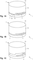
- the Figures 1A-1C show oblique images of a closure cap with a guarantee band and binding means in the initial state, after the guarantee ring has been separated and after being removed from the bottle neck.
- the closure lid 1 has a lid base body 2, which is formed from a circular cylindrical jacket 2a and a base 2b, as well as a guarantee band 3 with a band-shaped part, which is connected to the jacket 2a of the lid base body 2 via several webs 3a.
- the geometry of the web area is such that after the webs 3a have been torn open, the guarantee band 3 remains connected to the lid base body 2 via a connection 4 (cf. Figure 1B ). This connection remains even if the cap 1 is screwed on further and finally separated from the bottle neck.
- the lid base body is therefore still held via the connections via the guarantee band 3 remaining on the bottle neck, even after opening.
- the band-shaped part is thickened inwards, so that an undercut is created behind the band-shaped part in the direction of the bottom 2b.
- the closure lid 1 is made of plastic (in particular polyethylene PE or polypropylene PP) and has an internal thread in a manner known per se for screwing onto a bottle, in particular a beverage bottle made of PET or glass.
- the closure lid 1 is manufactured using the injection molding process, the guarantee band 3 is then manufactured by using a cutting device to make slots 3b between the remaining webs 3a and by folding a lower section of the band-shaped part inwards, so that the thickening results.
- the invention can also be used with other types of lids, e.g. B. with those made of sheet metal or with those in which the guarantee band and / or the binding means is already formed during injection molding without an additional cutting process. Instead of a single connection, several connections can remain after the webs have been severed in order to continue to hold the lid base body 2 on the bottle neck.
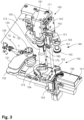
- the Figure 2 is a side view of an embodiment of the device according to the invention for testing a connection of a guarantee band and a connecting means of a closure lid with a lid base body and for testing a tightness of the lid base body.
- the Figure 3 shows a first oblique view Figure 4 a second oblique view and the Figure 5 a detailed view of the interaction area of the device with the closure lid.
- the device is used to test closure lids with a guarantee band 3 and connections 4 of a tether.
- the testing device 100 includes a testing unit 150, which is arranged on a base plate 155.
- the base plate 155 forms an inclined support surface for the test unit 150; its main plane is oriented vertically.
- a rail 161 of a linear guide 160 is attached to the support surface of the base plate 155.
- a spindle 165 with the associated drive, a servo motor 166 is also mounted at its upper end on the base plate 155 and at its lower end on a base plate (not shown here) of the testing device 100.
- the servo motor 166 (or alternatively a stepper motor) is arranged below the base plate, its output is connected to the spindle 165.
- the longitudinal axis of the spindle 165 runs parallel to the support surface and thus to the rail 161 of the linear guide 160.
- the spindle 165 cooperates with a ball recirculating system which is arranged on a carriage 162.
- the carriage 162 has guide elements that cooperate with the rail 161. By actuating the spindle 165 using the servo motor 166, the carriage can be moved along the rail 161.
- the testing unit 150 further comprises a circular cylindrical mandrel 170, which is connected to the base plate 155 via a force measuring unit 171.
- the longitudinal extent of the mandrel 170 runs parallel to the support surface, to the rail 161 and to the spindle 165.
- the force measuring unit 171 measures compressive forces transmitted to the end face of the mandrel 170.
- the mandrel 170 comprises a shaft 172 and a head 173 formed at the free end on the shaft 172. In the area of the head 173, the diameter of the mandrel increases Mandrel 170 so that it essentially corresponds to the free inside diameter of the closure lid.
- a carrier 181 is connected to the carriage 162, which can be moved along the rail 161 with the aid of the linear guide 160.
- a driving sleeve 180 is arranged on a first leg of the same. An oblique image of the same is in the Figure 6 shown.
- the driving sleeve 180 has a cylindrical section with a contact area 180a for a closure cover, in which a bead 180b is formed for gripping behind the guarantee band.
- a shaft area 180c At the rear of the contact area 180a there is a shaft area 180c, which merges into a fastening flange 180d.
- the driving sleeve 180 is attached to the carrier 181 in an interchangeable manner using the fastening flange 180d.
- the driving sleeve 180 has two axial grooves 180e, 180f, which are arranged opposite one another on the outer jacket, running from the fastening flange 180d over the shaft area 180c to the contact area 180a.
- the driving sleeve 180 encloses the mandrel 170 coaxially. With the help of the linear guide 160, the driving sleeve 180 can be moved along the mandrel 170.
- a holder 193 on the base plate 155 Arranged via a holder 193 on the base plate 155 are two cutting knives 191, 192, the cutting edges of which extend parallel to the jacket of the mandrel 170 at a predetermined distance. The distance can be adjusted manually to adapt to different cap diameters.
- the cutting knives 191, 192 are fastened in radial guides.
- the cutting knives 191, 192 like the mandrel 170, are arranged stationary and all three elements have a fixed location reference.
- the cutting knives 191, 192 and the driving sleeve 180 are arranged so that the cutting edges of the cutting knives 191, 192 are received in the grooves of the driving sleeve 180 when the driving sleeve 180 is moved over the area of the cutting knives 191, 192.
- the driving sleeve 180 can thus be moved from a position completely below the cutting blades 191, 192 to a position completely above the cutting blades 191, 192. If a guarantee band is taken along by the driving sleeve 180 by the bead 180b interacting with the inwardly projecting section or the thickening of the guarantee band, this will be the case Band cut at two diametrically opposite points by the two cutting knives 191, 192, so that two arcuate sections of 180 ° each are formed.
- the testing device 150 further comprises a sealing stamp 140.
- This includes a shaft 141 and a head 142 arranged on the front side, at the free end.
- the shaft 141 is fastened at its rear end to a second leg of the carrier 181.
- the sealing stamp 140 and the driving sleeve 180 are therefore always moved together in the vertical direction.
- the head 142 has an external geometry that essentially corresponds to that of a bottle neck and neck in the section that interacts with the inside of a closure lid.
- a gas supply 146 is arranged centrally in the shaft and opens into a cylindrical recess 147 in the head 142.
- the recess 147 is surrounded by a circular wall 148 (cf. Figure 4 ).
- the testing device 150 further comprises a table 151.
- a feed channel 156 with a rectangular cross section is arranged on this, through which the closure cover is guided over the surface of the table 151.
- a first stop 152 is arranged on the table and includes two stop plates for positioning the closure lid in a first position.
- the feed channel 156 has an opening at the top in this area so that the sealing stamp 140 can be inserted into the closure lid from above.
- the first stop 152 can be raised by means of a pneumatic cylinder 153, so that the closure lid is released and its further transport in the feed channel 156 is made possible.
- a second stop 154 is also attached to the table.
- the second stop 154 is used to position the closure lid in a second position in which the driving sleeve 180 can penetrate into the closure lid.
- the feed channel 156 has a cutout at its end facing the second stop 154.
- both stops 152, 154 in the feed direction of the closure lid can be adjusted manually in order to adapt the device to different closure lid diameters.
- Both stops can be provided with sensors (not shown) so that it can be determined whether a closure cover is available at the respective stop for the corresponding test.
- two elements are also pivotally mounted about a vertical axis in such a way that they can be moved selectively and individually into a position in which they cover an area which lies in the extension of the longitudinal axis of the mandrel below its free end.
- These elements are a boundary plate 131 and a discharge table 132 arranged underneath. Both are pivotally mounted on a tower 133 mounted on the table 151 at its lower end.
- the pivoting movement of the limiting plate 131 is controlled via a first pneumatic cylinder 135 arranged above the table 151, and the pivoting movement of the removal table 132 is controlled via a second pneumatic cylinder 136 arranged below the table 151.
- the test method carried out with the device according to the invention is explained below.
- the device is in the Figures 2-5 Starting position shown:
- the carrier 181 with the sealing stamp 140 and the driving sleeve 180 is in an upper, retracted position, and the first stop 152 is activated, ie in the position lowered onto the table 151.
- a closure lid is conveyed through the feed channel 156 onto the table 151. It rests with the bottom 2b of the lid base body 2 on the support surface of the table 151, the opening and the guarantee band 3 point upwards.
- the end position of the closure lid 1 is specified by the activated first stop 152. It lies centrally under the sealing stamp 140 along the direction of movement of the table 151 and the driving sleeve 180.
- the carrier 181 and thus in particular the sealing stamp 140 is lowered until the head 142 of the sealing stamp 140 penetrates into the closure lid 1 and is supported by the wall 148 on the inside of the lid.
- the closure lid 1 is clamped with its base 2b between the table 151 and the head 142 of the sealing stamp 140.
- a sealed chamber is now formed between the sealing stamp 140 and the closure lid.
- the leak test can now be carried out. Compressed air is introduced into the chamber through the gas supply 146 in the sealing stamp 140 until an excess pressure of 0.5 bar is reached. When this predetermined overpressure is reached, it is detected by a pressure measuring device in the feed and the valve in the feed is closed. After a specified waiting time of e.g. B. 5 s, the internal pressure is twice at a predetermined time interval of z. B. 1 s measured and the pressure drop between these measurements determined.
- the tightness of the sealing lid can be classified based on the pressure drop: pressure drop assessment Classification up to 0.008 bar good green 0.008 - 0.050 bar sufficient yellow over 0.050 bar insufficient red
- Additional measured values can be recorded and evaluated. For example, a series of measurements of the pressure drop can be approximated by a linear or non-linear function.
- the chamber is vented.
- the carrier 181 is then raised with the sealing stamp 140, with the head 142 of the sealing stamp 140 leaving the interior of the closure lid and releasing it.
- the first stop 152 can be moved upwards by means of the pneumatic cylinder 153, so that the closure lid can be transported further up to the second stop 154.
- the carrier 181 and thus in particular the driving sleeve 180 is moved downwards until its contact area 180a with the bead 180b has penetrated into the closure cover.
- the bead 180b temporarily pushes the inwardly projecting part of the guarantee band 3 radially outwards. Due to its elasticity, it snaps back inwards immediately after the bead 180b has passed through, so that the bead 180b is positioned behind a corresponding undercut.
- the driving sleeve 180 with the closure cover is now moved upwards with the help of the linear guide 160.
- the mandrel 170 enters the interior of the closure lid until its end face contacts the inner surface of the lid base.
- the limiting plate 131 is pivoted in. After being swiveled in, its upper main surface is parallel to the outer surface of the lid at a small distance (0.5-3 mm).
- the discharge table 132 is also swiveled in.
- a further upward movement results in a growing tear-off force between the cover base body 2 supported on the mandrel 170 and the guarantee band 3 held on the bead 180b.
- the tear-off force is measured by the force measuring unit 171, and the corresponding force values are passed on to a processing unit .
- the guarantee band 3 tears off from the lid base body 2, but the guarantee band 3 remains connected to the lid base body 2 via the connections 4 of the connecting means.
- the driving sleeve 180 is moved further upwards away from the free end of the mandrel 170 until the connections 4 also break.
- the limiting plate 131 ensures that the closure cap essentially maintains its position at the free end of the mandrel 170, especially even if only a first one of the connections 4 has broken and asymmetrical forces act on the closure cap.
- the limiting plate 131 can be pivoted back into its starting position. Accordingly, the lid base body is released by the mandrel 170.
- the driving sleeve 180 also passes the cutting knives 191, 192 with the guarantee band 3 held on the bead 180b.
- the guarantee band 3 becomes cut into two parts by the two cutting knives 191, 192. Since these are no longer held back by the bead 180b, they fall down onto the discharge table 132 due to gravity.
- v 2 , v 4 (measuring speed) ⁇ v 1 (entry speed) ⁇ v 5 (cutting speed) ⁇ v 3 (distancing, rapid traverse).
- the measuring speed is usually specified by a standard and is, for example, 2 mm/s; the other speeds can be optimized with a view to high process reliability and a quick process.
- the positions are referenced here from the maximum extended position of the driving sleeve 180, in which its free end is only a slight distance of a few mm from the support surface of the table 151.
- elements of the testing device described can be easily replaced, namely the front part of the mandrel, the sleeve and the cutting blades.
- the Figure 7 shows a force-displacement diagram of a testing process for a closure lid with a guarantee ring and a connecting means with two connections.
- the path is entered along the horizontal axis 21 and the measured tear-off force is entered along the vertical axis 22.
- the tear-off force initially increases gradually from the contact of the end face of the mandrel 170 with the bottom 2b of the lid base body 2.
- the webs between the base body and the guarantee band in particular are stretched, which requires a certain amount of force.
- the guarantee band tears off the tear-off force drops gradually, with the time-delayed tearing of the individual bars to the guarantee band.
- Relevant variables that can be determined from the course are, in particular, the forces 24.1, 24.2 measured at the local maxima and the corresponding paths 23.1, 23.2 or the force 24.3 when a second connecting element of the connection means breaks and the associated path 23.3. They can be used to evaluate the quality of the connection between the guarantee band and the base body. If the force curve is examined in more detail, it is also visible that some webs tear later than others: late tearing indicates that the cutting edges of the knives used to create the slot geometry are becoming dull. Other peculiarities of the course can indicate that the lid has been incorrectly clamped in the testing device, whereupon the result can be rejected and the measurement can be automatically repeated on the next lid.
- the invention is not limited to the exemplary embodiment shown.
- constructive details of the individual components can be designed differently. Due to the speed of the measurement process and its reproducibility, the It is also advantageous to use the test unit in manual operation. In particular, the feeding can be simplified in this case.
- the invention creates a device which simplifies the testing of closure lids.
Landscapes
- Physics & Mathematics (AREA)
- General Physics & Mathematics (AREA)
- Closures For Containers (AREA)
Priority Applications (1)
| Application Number | Priority Date | Filing Date | Title |
|---|---|---|---|
| EP22193757.6A EP4332536B1 (fr) | 2022-09-02 | 2022-09-02 | Dispositif de vérification d'une liaison d'une bande de garantie et/ou d'au moins un moyen de raccordement d'un couvercle de fermeture doté d'un corps de base de couvercle et de vérification d'une étanchéité du corps de base de couvercle |
Applications Claiming Priority (1)
| Application Number | Priority Date | Filing Date | Title |
|---|---|---|---|
| EP22193757.6A EP4332536B1 (fr) | 2022-09-02 | 2022-09-02 | Dispositif de vérification d'une liaison d'une bande de garantie et/ou d'au moins un moyen de raccordement d'un couvercle de fermeture doté d'un corps de base de couvercle et de vérification d'une étanchéité du corps de base de couvercle |
Publications (3)
| Publication Number | Publication Date |
|---|---|
| EP4332536A1 true EP4332536A1 (fr) | 2024-03-06 |
| EP4332536B1 EP4332536B1 (fr) | 2025-10-29 |
| EP4332536C0 EP4332536C0 (fr) | 2025-10-29 |
Family
ID=83192174
Family Applications (1)
| Application Number | Title | Priority Date | Filing Date |
|---|---|---|---|
| EP22193757.6A Active EP4332536B1 (fr) | 2022-09-02 | 2022-09-02 | Dispositif de vérification d'une liaison d'une bande de garantie et/ou d'au moins un moyen de raccordement d'un couvercle de fermeture doté d'un corps de base de couvercle et de vérification d'une étanchéité du corps de base de couvercle |
Country Status (1)
| Country | Link |
|---|---|
| EP (1) | EP4332536B1 (fr) |
Citations (3)
| Publication number | Priority date | Publication date | Assignee | Title |
|---|---|---|---|---|
| US4899574A (en) * | 1989-02-01 | 1990-02-13 | The Mead Corporation | Method and apparatus for detecting leaks in a sealed container |
| WO2020053286A1 (fr) | 2018-09-14 | 2020-03-19 | Packsys Global Ag | Dispositif pour vérifier une fixation d'une bande de garantie d'une protection inviolable d'un couvercle comprenant un corps principal de couvercle |
| WO2022137098A1 (fr) * | 2020-12-23 | 2022-06-30 | Sacmi Cooperativa Meccanici Imola Societa' Cooperativa | Appareil et procédé de mesure destinés à des capsules |
-
2022
- 2022-09-02 EP EP22193757.6A patent/EP4332536B1/fr active Active
Patent Citations (3)
| Publication number | Priority date | Publication date | Assignee | Title |
|---|---|---|---|---|
| US4899574A (en) * | 1989-02-01 | 1990-02-13 | The Mead Corporation | Method and apparatus for detecting leaks in a sealed container |
| WO2020053286A1 (fr) | 2018-09-14 | 2020-03-19 | Packsys Global Ag | Dispositif pour vérifier une fixation d'une bande de garantie d'une protection inviolable d'un couvercle comprenant un corps principal de couvercle |
| WO2022137098A1 (fr) * | 2020-12-23 | 2022-06-30 | Sacmi Cooperativa Meccanici Imola Societa' Cooperativa | Appareil et procédé de mesure destinés à des capsules |
Also Published As
| Publication number | Publication date |
|---|---|
| EP4332536B1 (fr) | 2025-10-29 |
| EP4332536C0 (fr) | 2025-10-29 |
Similar Documents
| Publication | Publication Date | Title |
|---|---|---|
| EP3623791B1 (fr) | Dispositif de contrôle d'un raccordement d'une bande d'inviolabilité d'une protection d'originalité d'un couvercle de fermeture avec un corps de base de couvercle | |
| DE2026964C2 (de) | Vorrichtung zum Formen, Füllen und Verschließen von Kunststoffbehältern | |
| EP3957432B1 (fr) | Mandrin | |
| WO1999011451A1 (fr) | Procede pour la fabrication d'un recipient, ainsi que recipient pourvu d'orifices d'egalisation de pression | |
| DE2255057A1 (de) | Werkzeugbruch-anzeigevorrichtung | |
| CH702396B1 (de) | Verfahren und Vorrichtung zum fortlaufenden Vereinzeln und Ausrichten von einseitig geschlossenen zylindrischen Hohlkörpern, insbesondere von Schraubverschlüssen für Flaschen. | |
| DE602004005193T2 (de) | Vorrichtung zur herstellung von verschlüssen | |
| DE202020104970U1 (de) | Maschine zum Verschließen von Flaschen mit Verschlüssen aus verformbarem Material | |
| WO1998001268A1 (fr) | Procede de fabrication d'un recipient et recipient pourvu d'ouvertures d'equilibrage de la pression | |
| EP4187225B1 (fr) | Dispositif de contrôle d'une liaison d'une bande de garantie et/ou d'au moins un moyen d'attache d'un couvercle de fermeture avec un corps de base du couvercle et de contrôle d'une étanchéité du corps de base du couvercle | |
| EP4332536A1 (fr) | Dispositif de vérification d'une liaison d'une bande de garantie et/ou d'au moins un moyen de raccordement d'un couvercle de fermeture doté d'un corps de base de couvercle et de vérification d'une étanchéité du corps de base de couvercle | |
| EP0534096A2 (fr) | Procédé et dispositif pour examiner des impuretés dans des récipients | |
| EP3380420A2 (fr) | Installation et procédé permettant de séparer et/ou de contrôler des contenants | |
| EP2965899A1 (fr) | Dispositif destiné à séparer des ébauches d'emballage souples | |
| DE4324109B4 (de) | Gewindeprüfvorrichtung | |
| DE19505474C2 (de) | Verfahren und Vorrichtung zum Prüfen von Flaschen aus Kunststoff auf Kontaminationen | |
| DE102020206845B4 (de) | Verfahren zur Verbesserung der Leckprüfung von hohlen, mit einem Mundloch versehenen Kunststoffbehältern | |
| DE2457344A1 (de) | Geblasener behaelter aus kunststoff sowie verfahren und vorrichtung zu seiner herstellung | |
| DE102011002242A1 (de) | Hochgeschwindigkeits-Druck-Prüfvorrichtung zur Durchführung von Stauchversuchen | |
| EP2291320B1 (fr) | Dispositif et procédé de vérification de l' étanchéité de capuchons de fermeture sur des corps creux utilisés dans le domaine médical | |
| DE19918639A1 (de) | Verfahren und Vorrichtung zum Transportieren von insbesondere rohrförmigen Behältern | |
| DE102016212321A1 (de) | Vorrichtung und Verfahren zum Untersuchen von Behältern auf Fremdstoffe | |
| CH720555A1 (de) | Verfahren zum Fertigen eines Innengewindes an einem Behälter | |
| DE3609216C1 (en) | Nozzle for treating a running thread | |
| DE2216278A1 (de) | Verfahren zum Entfernen des Grates von der Grundfläche eines durch Blasformen hergestellten Gegenstandes und Vorrichtung zur Durchführung dieses Verfahrens |
Legal Events
| Date | Code | Title | Description |
|---|---|---|---|
| PUAI | Public reference made under article 153(3) epc to a published international application that has entered the european phase |
Free format text: ORIGINAL CODE: 0009012 |
|
| STAA | Information on the status of an ep patent application or granted ep patent |
Free format text: STATUS: THE APPLICATION HAS BEEN PUBLISHED |
|
| AK | Designated contracting states |
Kind code of ref document: A1 Designated state(s): AL AT BE BG CH CY CZ DE DK EE ES FI FR GB GR HR HU IE IS IT LI LT LU LV MC MK MT NL NO PL PT RO RS SE SI SK SM TR |
|
| STAA | Information on the status of an ep patent application or granted ep patent |
Free format text: STATUS: REQUEST FOR EXAMINATION WAS MADE |
|
| 17P | Request for examination filed |
Effective date: 20240321 |
|
| RBV | Designated contracting states (corrected) |
Designated state(s): AL AT BE BG CH CY CZ DE DK EE ES FI FR GB GR HR HU IE IS IT LI LT LU LV MC MK MT NL NO PL PT RO RS SE SI SK SM TR |
|
| GRAP | Despatch of communication of intention to grant a patent |
Free format text: ORIGINAL CODE: EPIDOSNIGR1 |
|
| STAA | Information on the status of an ep patent application or granted ep patent |
Free format text: STATUS: GRANT OF PATENT IS INTENDED |
|
| INTG | Intention to grant announced |
Effective date: 20240719 |
|
| GRAJ | Information related to disapproval of communication of intention to grant by the applicant or resumption of examination proceedings by the epo deleted |
Free format text: ORIGINAL CODE: EPIDOSDIGR1 |
|
| STAA | Information on the status of an ep patent application or granted ep patent |
Free format text: STATUS: REQUEST FOR EXAMINATION WAS MADE |
|
| INTC | Intention to grant announced (deleted) | ||
| GRAP | Despatch of communication of intention to grant a patent |
Free format text: ORIGINAL CODE: EPIDOSNIGR1 |
|
| STAA | Information on the status of an ep patent application or granted ep patent |
Free format text: STATUS: GRANT OF PATENT IS INTENDED |
|
| INTG | Intention to grant announced |
Effective date: 20250114 |
|
| GRAJ | Information related to disapproval of communication of intention to grant by the applicant or resumption of examination proceedings by the epo deleted |
Free format text: ORIGINAL CODE: EPIDOSDIGR1 |
|
| STAA | Information on the status of an ep patent application or granted ep patent |
Free format text: STATUS: REQUEST FOR EXAMINATION WAS MADE |
|
| GRAP | Despatch of communication of intention to grant a patent |
Free format text: ORIGINAL CODE: EPIDOSNIGR1 |
|
| STAA | Information on the status of an ep patent application or granted ep patent |
Free format text: STATUS: GRANT OF PATENT IS INTENDED |
|
| INTC | Intention to grant announced (deleted) | ||
| INTG | Intention to grant announced |
Effective date: 20250424 |
|
| GRAS | Grant fee paid |
Free format text: ORIGINAL CODE: EPIDOSNIGR3 |
|
| GRAA | (expected) grant |
Free format text: ORIGINAL CODE: 0009210 |
|
| STAA | Information on the status of an ep patent application or granted ep patent |
Free format text: STATUS: THE PATENT HAS BEEN GRANTED |
|
| AK | Designated contracting states |
Kind code of ref document: B1 Designated state(s): AL AT BE BG CH CY CZ DE DK EE ES FI FR GB GR HR HU IE IS IT LI LT LU LV MC MK MT NL NO PL PT RO RS SE SI SK SM TR |
|
| REG | Reference to a national code |
Ref country code: CH Ref legal event code: F10 Free format text: ST27 STATUS EVENT CODE: U-0-0-F10-F00 (AS PROVIDED BY THE NATIONAL OFFICE) Effective date: 20251029 Ref country code: GB Ref legal event code: FG4D Free format text: NOT ENGLISH Ref country code: CH Ref legal event code: R17 Free format text: ST27 STATUS EVENT CODE: U-0-0-R10-R17 (AS PROVIDED BY THE NATIONAL OFFICE) Effective date: 20251029 |
|
| REG | Reference to a national code |
Ref country code: DE Ref legal event code: R096 Ref document number: 502022005913 Country of ref document: DE |
|
| REG | Reference to a national code |
Ref country code: IE Ref legal event code: FG4D Free format text: LANGUAGE OF EP DOCUMENT: GERMAN |
|
| U01 | Request for unitary effect filed |
Effective date: 20251029 |
|
| U07 | Unitary effect registered |
Designated state(s): AT BE BG DE DK EE FI FR IT LT LU LV MT NL PT RO SE SI Effective date: 20251105 |
|
| PG25 | Lapsed in a contracting state [announced via postgrant information from national office to epo] |
Ref country code: NO Free format text: LAPSE BECAUSE OF FAILURE TO SUBMIT A TRANSLATION OF THE DESCRIPTION OR TO PAY THE FEE WITHIN THE PRESCRIBED TIME-LIMIT Effective date: 20260129 |
|
| PG25 | Lapsed in a contracting state [announced via postgrant information from national office to epo] |
Ref country code: HR Free format text: LAPSE BECAUSE OF FAILURE TO SUBMIT A TRANSLATION OF THE DESCRIPTION OR TO PAY THE FEE WITHIN THE PRESCRIBED TIME-LIMIT Effective date: 20251029 |
|
| PG25 | Lapsed in a contracting state [announced via postgrant information from national office to epo] |
Ref country code: RS Free format text: LAPSE BECAUSE OF FAILURE TO SUBMIT A TRANSLATION OF THE DESCRIPTION OR TO PAY THE FEE WITHIN THE PRESCRIBED TIME-LIMIT Effective date: 20260129 |
|
| PG25 | Lapsed in a contracting state [announced via postgrant information from national office to epo] |
Ref country code: IS Free format text: LAPSE BECAUSE OF FAILURE TO SUBMIT A TRANSLATION OF THE DESCRIPTION OR TO PAY THE FEE WITHIN THE PRESCRIBED TIME-LIMIT Effective date: 20260228 |
|
| PG25 | Lapsed in a contracting state [announced via postgrant information from national office to epo] |
Ref country code: PL Free format text: LAPSE BECAUSE OF FAILURE TO SUBMIT A TRANSLATION OF THE DESCRIPTION OR TO PAY THE FEE WITHIN THE PRESCRIBED TIME-LIMIT Effective date: 20251029 |