EP4332587B1 - Sensormontagevorrichtung für radarprüfung - Google Patents
Sensormontagevorrichtung für radarprüfung Download PDFInfo
- Publication number
- EP4332587B1 EP4332587B1 EP22192891.4A EP22192891A EP4332587B1 EP 4332587 B1 EP4332587 B1 EP 4332587B1 EP 22192891 A EP22192891 A EP 22192891A EP 4332587 B1 EP4332587 B1 EP 4332587B1
- Authority
- EP
- European Patent Office
- Prior art keywords
- sensor
- frame
- vehicle part
- testing apparatus
- relative
- Prior art date
- Legal status (The legal status is an assumption and is not a legal conclusion. Google has not performed a legal analysis and makes no representation as to the accuracy of the status listed.)
- Active
Links
Images



Classifications
-
- G—PHYSICS
- G01—MEASURING; TESTING
- G01S—RADIO DIRECTION-FINDING; RADIO NAVIGATION; DETERMINING DISTANCE OR VELOCITY BY USE OF RADIO WAVES; LOCATING OR PRESENCE-DETECTING BY USE OF THE REFLECTION OR RERADIATION OF RADIO WAVES; ANALOGOUS ARRANGEMENTS USING OTHER WAVES
- G01S7/00—Details of systems according to groups G01S13/00, G01S15/00, G01S17/00
- G01S7/02—Details of systems according to groups G01S13/00, G01S15/00, G01S17/00 of systems according to group G01S13/00
- G01S7/40—Means for monitoring or calibrating
-
- G—PHYSICS
- G01—MEASURING; TESTING
- G01D—MEASURING NOT SPECIALLY ADAPTED FOR A SPECIFIC VARIABLE; ARRANGEMENTS FOR MEASURING TWO OR MORE VARIABLES NOT COVERED IN A SINGLE OTHER SUBCLASS; TARIFF METERING APPARATUS; MEASURING OR TESTING NOT OTHERWISE PROVIDED FOR
- G01D11/00—Component parts of measuring arrangements not specially adapted for a specific variable
- G01D11/30—Supports specially adapted for an instrument; Supports specially adapted for a set of instruments
-
- G—PHYSICS
- G01—MEASURING; TESTING
- G01R—MEASURING ELECTRIC VARIABLES; MEASURING MAGNETIC VARIABLES
- G01R29/00—Arrangements for measuring or indicating electric quantities not covered by groups G01R19/00 - G01R27/00
- G01R29/08—Measuring electromagnetic field characteristics
- G01R29/0864—Measuring electromagnetic field characteristics characterised by constructional or functional features
- G01R29/0871—Complete apparatus or systems; circuits, e.g. receivers or amplifiers
-
- F—MECHANICAL ENGINEERING; LIGHTING; HEATING; WEAPONS; BLASTING
- F16—ENGINEERING ELEMENTS AND UNITS; GENERAL MEASURES FOR PRODUCING AND MAINTAINING EFFECTIVE FUNCTIONING OF MACHINES OR INSTALLATIONS; THERMAL INSULATION IN GENERAL
- F16M—FRAMES, CASINGS OR BEDS OF ENGINES, MACHINES OR APPARATUS, NOT SPECIFIC TO ENGINES, MACHINES OR APPARATUS PROVIDED FOR ELSEWHERE; STANDS; SUPPORTS
- F16M11/00—Stands or trestles as supports for apparatus or articles placed thereon ; Stands for scientific apparatus such as gravitational force meters
- F16M11/02—Heads
- F16M11/04—Means for attachment of apparatus; Means allowing adjustment of the apparatus relatively to the stand
- F16M11/041—Allowing quick release of the apparatus
-
- F—MECHANICAL ENGINEERING; LIGHTING; HEATING; WEAPONS; BLASTING
- F16—ENGINEERING ELEMENTS AND UNITS; GENERAL MEASURES FOR PRODUCING AND MAINTAINING EFFECTIVE FUNCTIONING OF MACHINES OR INSTALLATIONS; THERMAL INSULATION IN GENERAL
- F16M—FRAMES, CASINGS OR BEDS OF ENGINES, MACHINES OR APPARATUS, NOT SPECIFIC TO ENGINES, MACHINES OR APPARATUS PROVIDED FOR ELSEWHERE; STANDS; SUPPORTS
- F16M11/00—Stands or trestles as supports for apparatus or articles placed thereon ; Stands for scientific apparatus such as gravitational force meters
- F16M11/02—Heads
- F16M11/04—Means for attachment of apparatus; Means allowing adjustment of the apparatus relatively to the stand
- F16M11/06—Means for attachment of apparatus; Means allowing adjustment of the apparatus relatively to the stand allowing pivoting
- F16M11/08—Means for attachment of apparatus; Means allowing adjustment of the apparatus relatively to the stand allowing pivoting around a vertical axis, e.g. panoramic heads
-
- F—MECHANICAL ENGINEERING; LIGHTING; HEATING; WEAPONS; BLASTING
- F16—ENGINEERING ELEMENTS AND UNITS; GENERAL MEASURES FOR PRODUCING AND MAINTAINING EFFECTIVE FUNCTIONING OF MACHINES OR INSTALLATIONS; THERMAL INSULATION IN GENERAL
- F16M—FRAMES, CASINGS OR BEDS OF ENGINES, MACHINES OR APPARATUS, NOT SPECIFIC TO ENGINES, MACHINES OR APPARATUS PROVIDED FOR ELSEWHERE; STANDS; SUPPORTS
- F16M11/00—Stands or trestles as supports for apparatus or articles placed thereon ; Stands for scientific apparatus such as gravitational force meters
- F16M11/02—Heads
- F16M11/04—Means for attachment of apparatus; Means allowing adjustment of the apparatus relatively to the stand
- F16M11/06—Means for attachment of apparatus; Means allowing adjustment of the apparatus relatively to the stand allowing pivoting
- F16M11/12—Means for attachment of apparatus; Means allowing adjustment of the apparatus relatively to the stand allowing pivoting in more than one direction
- F16M11/121—Means for attachment of apparatus; Means allowing adjustment of the apparatus relatively to the stand allowing pivoting in more than one direction constituted of several dependent joints
- F16M11/123—Means for attachment of apparatus; Means allowing adjustment of the apparatus relatively to the stand allowing pivoting in more than one direction constituted of several dependent joints the axis of rotation intersecting in a single point, e.g. by using gimbals
-
- F—MECHANICAL ENGINEERING; LIGHTING; HEATING; WEAPONS; BLASTING
- F16—ENGINEERING ELEMENTS AND UNITS; GENERAL MEASURES FOR PRODUCING AND MAINTAINING EFFECTIVE FUNCTIONING OF MACHINES OR INSTALLATIONS; THERMAL INSULATION IN GENERAL
- F16M—FRAMES, CASINGS OR BEDS OF ENGINES, MACHINES OR APPARATUS, NOT SPECIFIC TO ENGINES, MACHINES OR APPARATUS PROVIDED FOR ELSEWHERE; STANDS; SUPPORTS
- F16M11/00—Stands or trestles as supports for apparatus or articles placed thereon ; Stands for scientific apparatus such as gravitational force meters
- F16M11/20—Undercarriages with or without wheels
- F16M11/2007—Undercarriages with or without wheels comprising means allowing pivoting adjustment
- F16M11/2035—Undercarriages with or without wheels comprising means allowing pivoting adjustment in more than one direction
- F16M11/2057—Undercarriages with or without wheels comprising means allowing pivoting adjustment in more than one direction for tilting and rolling
-
- F—MECHANICAL ENGINEERING; LIGHTING; HEATING; WEAPONS; BLASTING
- F16—ENGINEERING ELEMENTS AND UNITS; GENERAL MEASURES FOR PRODUCING AND MAINTAINING EFFECTIVE FUNCTIONING OF MACHINES OR INSTALLATIONS; THERMAL INSULATION IN GENERAL
- F16M—FRAMES, CASINGS OR BEDS OF ENGINES, MACHINES OR APPARATUS, NOT SPECIFIC TO ENGINES, MACHINES OR APPARATUS PROVIDED FOR ELSEWHERE; STANDS; SUPPORTS
- F16M11/00—Stands or trestles as supports for apparatus or articles placed thereon ; Stands for scientific apparatus such as gravitational force meters
- F16M11/20—Undercarriages with or without wheels
- F16M11/2085—Undercarriages with or without wheels comprising means allowing sideward adjustment, i.e. left-right translation of the head relatively to the undercarriage
-
- F—MECHANICAL ENGINEERING; LIGHTING; HEATING; WEAPONS; BLASTING
- F16—ENGINEERING ELEMENTS AND UNITS; GENERAL MEASURES FOR PRODUCING AND MAINTAINING EFFECTIVE FUNCTIONING OF MACHINES OR INSTALLATIONS; THERMAL INSULATION IN GENERAL
- F16M—FRAMES, CASINGS OR BEDS OF ENGINES, MACHINES OR APPARATUS, NOT SPECIFIC TO ENGINES, MACHINES OR APPARATUS PROVIDED FOR ELSEWHERE; STANDS; SUPPORTS
- F16M11/00—Stands or trestles as supports for apparatus or articles placed thereon ; Stands for scientific apparatus such as gravitational force meters
- F16M11/20—Undercarriages with or without wheels
- F16M11/24—Undercarriages with or without wheels changeable in height or length of legs, also for transport only, e.g. by means of tubes screwed into each other
-
- G—PHYSICS
- G01—MEASURING; TESTING
- G01B—MEASURING LENGTH, THICKNESS OR SIMILAR LINEAR DIMENSIONS; MEASURING ANGLES; MEASURING AREAS; MEASURING IRREGULARITIES OF SURFACES OR CONTOURS
- G01B5/00—Measuring arrangements characterised by the use of mechanical techniques
- G01B5/0002—Arrangements for supporting, fixing or guiding the measuring instrument or the object to be measured
-
- G—PHYSICS
- G01—MEASURING; TESTING
- G01D—MEASURING NOT SPECIALLY ADAPTED FOR A SPECIFIC VARIABLE; ARRANGEMENTS FOR MEASURING TWO OR MORE VARIABLES NOT COVERED IN A SINGLE OTHER SUBCLASS; TARIFF METERING APPARATUS; MEASURING OR TESTING NOT OTHERWISE PROVIDED FOR
- G01D11/00—Component parts of measuring arrangements not specially adapted for a specific variable
- G01D11/24—Housings ; Casings for instruments
- G01D11/245—Housings for sensors
-
- G—PHYSICS
- G01—MEASURING; TESTING
- G01M—TESTING STATIC OR DYNAMIC BALANCE OF MACHINES OR STRUCTURES; TESTING OF STRUCTURES OR APPARATUS, NOT OTHERWISE PROVIDED FOR
- G01M17/00—Testing of vehicles
-
- G—PHYSICS
- G01—MEASURING; TESTING
- G01N—INVESTIGATING OR ANALYSING MATERIALS BY DETERMINING THEIR CHEMICAL OR PHYSICAL PROPERTIES
- G01N29/00—Investigating or analysing materials by the use of ultrasonic, sonic or infrasonic waves; Visualisation of the interior of objects by transmitting ultrasonic or sonic waves through the object
- G01N29/22—Details, e.g. general constructional or apparatus details
- G01N29/26—Arrangements for orientation or scanning by relative movement of the head and the sensor
- G01N29/265—Arrangements for orientation or scanning by relative movement of the head and the sensor by moving the sensor relative to a stationary material
-
- G—PHYSICS
- G01—MEASURING; TESTING
- G01S—RADIO DIRECTION-FINDING; RADIO NAVIGATION; DETERMINING DISTANCE OR VELOCITY BY USE OF RADIO WAVES; LOCATING OR PRESENCE-DETECTING BY USE OF THE REFLECTION OR RERADIATION OF RADIO WAVES; ANALOGOUS ARRANGEMENTS USING OTHER WAVES
- G01S13/00—Systems using the reflection or reradiation of radio waves, e.g. radar systems; Analogous systems using reflection or reradiation of waves whose nature or wavelength is irrelevant or unspecified
- G01S13/88—Radar or analogous systems specially adapted for specific applications
-
- G—PHYSICS
- G01—MEASURING; TESTING
- G01S—RADIO DIRECTION-FINDING; RADIO NAVIGATION; DETERMINING DISTANCE OR VELOCITY BY USE OF RADIO WAVES; LOCATING OR PRESENCE-DETECTING BY USE OF THE REFLECTION OR RERADIATION OF RADIO WAVES; ANALOGOUS ARRANGEMENTS USING OTHER WAVES
- G01S7/00—Details of systems according to groups G01S13/00, G01S15/00, G01S17/00
- G01S7/02—Details of systems according to groups G01S13/00, G01S15/00, G01S17/00 of systems according to group G01S13/00
- G01S7/027—Constructional details of housings, e.g. form, type, material or ruggedness
-
- G—PHYSICS
- G01—MEASURING; TESTING
- G01S—RADIO DIRECTION-FINDING; RADIO NAVIGATION; DETERMINING DISTANCE OR VELOCITY BY USE OF RADIO WAVES; LOCATING OR PRESENCE-DETECTING BY USE OF THE REFLECTION OR RERADIATION OF RADIO WAVES; ANALOGOUS ARRANGEMENTS USING OTHER WAVES
- G01S7/00—Details of systems according to groups G01S13/00, G01S15/00, G01S17/00
- G01S7/02—Details of systems according to groups G01S13/00, G01S15/00, G01S17/00 of systems according to group G01S13/00
- G01S7/40—Means for monitoring or calibrating
- G01S7/4004—Means for monitoring or calibrating of parts of a radar system
- G01S7/4039—Means for monitoring or calibrating of parts of a radar system of sensor or antenna obstruction, e.g. dirt- or ice-coating
-
- G—PHYSICS
- G01—MEASURING; TESTING
- G01S—RADIO DIRECTION-FINDING; RADIO NAVIGATION; DETERMINING DISTANCE OR VELOCITY BY USE OF RADIO WAVES; LOCATING OR PRESENCE-DETECTING BY USE OF THE REFLECTION OR RERADIATION OF RADIO WAVES; ANALOGOUS ARRANGEMENTS USING OTHER WAVES
- G01S7/00—Details of systems according to groups G01S13/00, G01S15/00, G01S17/00
- G01S7/02—Details of systems according to groups G01S13/00, G01S15/00, G01S17/00 of systems according to group G01S13/00
- G01S7/40—Means for monitoring or calibrating
- G01S7/4052—Means for monitoring or calibrating by simulation of echoes
- G01S7/4082—Means for monitoring or calibrating by simulation of echoes using externally generated reference signals, e.g. via remote reflector or transponder
- G01S7/4086—Means for monitoring or calibrating by simulation of echoes using externally generated reference signals, e.g. via remote reflector or transponder in a calibrating environment, e.g. anechoic chamber
-
- G—PHYSICS
- G21—NUCLEAR PHYSICS; NUCLEAR ENGINEERING
- G21C—NUCLEAR REACTORS
- G21C17/00—Monitoring; Testing ; Maintaining
- G21C17/017—Inspection or maintenance of pipe-lines or tubes in nuclear installations
-
- G—PHYSICS
- G01—MEASURING; TESTING
- G01R—MEASURING ELECTRIC VARIABLES; MEASURING MAGNETIC VARIABLES
- G01R31/00—Arrangements for testing electric properties; Arrangements for locating electric faults; Arrangements for electrical testing characterised by what is being tested not provided for elsewhere
- G01R31/005—Testing of electric installations on transport means
Definitions
- the present disclosure relates to a sensor mounting device and a method of mounting the same.
- the present disclosure is particularly relevant to testing of vehicular radar units.
- Modern vehicles which possess autonomous driving functionality require precise sensing of their immediate environment and beyond to be operated safely. This is often achieved by a variety of sensors, such as one or more radar sensors that are mounted to the vehicle body, e.g. behind a fascia element such as a vehicle bumper.
- sensors such as one or more radar sensors that are mounted to the vehicle body, e.g. behind a fascia element such as a vehicle bumper.
- Testing is undertaken in an isolated environment (e.g. anechoic chamber) where there is good control over target size and other parameters (speed, amplitude, position) to verify radar performance over mechanical tolerances of assembly and to fulfil functional requirements in terms of accuracy and detection range/ability.
- anechoic chamber e.g. anechoic chamber
- radar sensor tests may be performed by mounting a sensor to a robotic arm and further mounting the fascia in front of the sensor, with a positioning device for setting the distance between radar and fascia in a normal direction, i.e. one degree of freedom for adjustment.
- a positioning device for setting the distance between radar and fascia in a normal direction, i.e. one degree of freedom for adjustment.
- Three-dimensional motion of the sensor is articulated by the robot arm but additional movement of the fascia relative to the sensor is restricted.
- the test method typically involves the radar sensor unit, mounted on the robotic arm, being moved completely (e.g. azimuth elevation, translation x, y, z) within the range of field of view of the radar to measure the radar detection parameters with the fascia in place. The test is repeated with/without fascia to measure signal degradation.
- mounting device include: CN113203996A ; CN110398736A ; CN113253218A ; MIKE KOHLER ET AL: "Considerations for future automotive radar in the frequency range above 100 GHz", GERMAN MICROWAVE CONFERENCE, 2010, IEEE, PISCATAWAY, NJ, USA, 15 March 2010, pages 284-287 ; JP2016136091A ; DE102004045801B3 ; US2006/065795A1 ; US2018/120242A1 .
- a sensor mounting apparatus/device for testing comprising a first mounting device for mounting a sensor, and a second mounting device for mounting a vehicle part, wherein the second mounting device is movable in at least three directions relative to the first mounting device.
- the directions may be selected from: forward and back, left and right, up and down, roll, yaw and pitch.
- the invention facilitates, in addition to mounting of the sensor, more flexibility and control for verification tests via a mount system for the vehicle part that moves independently from the sensor.
- a mount system for the vehicle part that moves independently from the sensor.
- fascia i.e. the vehicle part
- the sensor e.g. radar
- a particular form may have five degrees of freedom of movement, namely: forward and back, left and right, up and down, yaw and pitch.
- the invention may be described in general terms as a "fascia motion frame" because it enables motion of a fascia/vehicle part relative to a sensor by the mechanism of a successive series of frames, each responsible for a degree of movement.
- the sensor testing apparatus may be in the form of a frame system.
- the vehicle body part mounting device may be comprised of a first frame located around (or extending from) and moveable relative to the first/sensor mounting element/device (e.g. being a sensor mounting plate for the radar) which is moveable relative to a second frame, that is in turn moveable relative to a third frame.
- the third frame provides a forwards/backwards tilt movement relative to the second frame, while the second frame is configured for sideways
- each frame is configured for vertical movement (up and down) movement relative to the sensor.
- the functions/order of each frame may be interchanged, so long as each provides a degree of movement.
- the third frame may include additional mounting features for supporting (e.g. connecting and/or clipping to) the vehicle part.
- additional mounting features may have further degrees of movement for mounting the vehicle part.
- the part may be mountable with one or more adjustments toward and away from, relative to, the sensor which provides for yaw adjustment. A further roll adjustment may be implemented.
- the classic example of movement in three-dimensional space can entail translational movements forward and back, left and right, and up and down; and rotational movement about the X, Y, and Z axes (defining roll, yaw and pitch respectively).
- the sensor test apparatus comprises a first frame that is moveable up and down relative to a sensor mount (which is in turn attachable to a robotic arm), e.g. by adjustment of a threaded element arranged vertically at one side of the frame, applying force against an adjacent face of the sensor mount, and causing (vertical) guide rods extending from an opposite side of the sensor mount to move through openings in the first frame, thereby enabling controlled translational vertical/up/down movement between the first frame and sensor mount.
- a sensor mount which is in turn attachable to a robotic arm
- a second frame is provided, moveable left and right (sideways) relative to the first frame and sensor mount, e.g. by adjustment of another threaded member, arranged on a horizontal axis, at one side of the second frame, acting against an adjacent face of the first frame, while (horizontal) guide rods extending from an opposite side of the first frame move through openings in the second frame to enable controlled translational sideways/left/right movement between the second frame and both the first frame and sensor mount.
- a third frame may be provided, moveable for pitch rotation relative to the first/second frames and sensor mount, e.g. by adjustment of a rotatable knob, arranged on a horizontal axis, at one side of the third frame, enabling a controlled tilt/pitch movement between the third frame and each of the first/second frame and sensor mount.
- the third frame is configured to support a vehicle part that is able to move independently relative to the sensor mount in each of the vertical, sideways and tilting directions indicated above.
- Alternative configurations may provide for a different selection of movement for each frame, from six possibilities, namely forward and back, left and right, up and down, roll, yaw and pitch.
- the frames may be generally concentrically nestled together.
- the first frame which may be the smallest, is surrounded and fits inside the second frame which in turn may be surrounded and fits inside the third frame.
- the third frame may be located forward from the second frame so it is clear of the guide rods extending between first and second frames which control translational movement.
- the third or outermost frame may include mounting features for a vehicle part and/or additional adjustment elements, e.g. extensible arms from positions at opposing (e.g. upper and lower) edges of the third frame.
- the arms may extend from a mounting block that is pivotally connected to the third frame, to effectively permit yaw adjustment of the vehicle part relative to a radar middle point.
- the sensor mount is a plate connectable from one side (or therethrough) to an articulated robot arm.
- a sensor e.g. a radar sensor, is mountable on the other side to transmit away from the robotic arm, in use, towards an RTS.
- the invention may be expressed as a method according to claim 14.
- the method provides for mounting a vehicle part for independent movement relative to a sensor, where the independent relative movement comprises at least three degrees of freedom selected from: forward and back, left and right, up and down, roll, yaw and pitch.
- the senor is mounted to a sensor mount that is in fixed connection to a robotic arm.
- the method is used in the context of testing properties of a radar sensor when the vehicle part is disposed between it and a radar target simulator.
- the term “comprising” as used in this specification means “consisting at least in part of” such that interpreting each statement in this specification that includes the term “comprising”, features other than that or those prefaced by the term may also be present.
- Related terms such as “comprise” and “comprises” are to be interpreted in the same manner.
- Directional terms such as “vertical”, “horizontal”, “up”, “down”, “sideways”, “upper” and “lower” are used for convenience of explanation usually with reference to the orientation shown in illustrations and are not intended to be ultimately limiting if an equivalent function can be achieved with an alternative dimension and/or direction. Indeed, in the present case a term such as “horizontal” axis or “vertical” axis can be affected by the orientation imposed on the sensor mounting structure by the robotic arm. Therefore, all directional terms are relative to each other.
- a sensor testing apparatus is illustrated by Figure 1 .
- the testing apparatus or "test rig”, generally denoted 10 is associated with a sensor that would be affixed to mounting plate 11 by suitable fasteners to a robotic arm A.
- the arm A would be installed in an anechoic chamber at a distance from an RTS, but the details of the testing procedure are not the subject of the present invention.
- the invention relates to the physical construction of the sensor mounting apparatus, for use in a testing situation, namely a mechanism to independently mount a vehicle part (not shown in Figure 1 , e.g. fascia/bumper) relative to a sensor (not shown) attached to the sensor mounting plate 11.
- the apparatus primarily consists of three frames surrounding the mounting plate 11 that, combined, are able to move the fascia through at least three degrees of freedom relative to an antenna middle point P (also known as a pivot point).
- a first innermost frame 12 surrounds the sensor mounting plate 11 and, in this embodiment, is configured for vertical movement relative thereto, while a second mid-frame 13 surrounds the first frame and is, in this embodiment, configured for sideways movement relative thereto (and the sensor mount plate 11).
- a third, largest and outermost, frame 14 is, in this embodiment, pivotally connected to brackets 15 extending forwardly from opposing sides of the second frame 13 and configured for adjusting/tilting its pitch about a generally horizontal axis H, relative to the other frames 12/13 and centrally located sensor mount plate 11.
- first frame 12 is moveable up and down relative to the sensor mount 11 (which in turn is attachable to the robotic arm A). Adjustment may be achieved by a first threaded element 16, arranged vertically through one side (in this case the lower edge) of frame 12, via a receiving threaded opening 12a. A proximate end of element 16 acts against an adjacent edge 11a of the sensor mount 11. Force applied via extension of first threaded element 16 through and from first frame 12 causes vertical translation and an increase in the distance between the lower edge of frame 12 and adjacent edge 11a of the sensor mount plate 11.
- Translational movement in the vertical direction is controlled by at least two guide rods 17 (unthreaded) extending from the opposite (upper) edge 11b of sensor mount plate 11 through unthreaded openings 12b in an adjacent side/edge of first frame 12. Widening the distance between frame 12 and plate edge 11a at the threaded member side causes a corresponding narrowing of the distance between sensor plate edge 11b and frame 12. Accordingly, controlled translational vertical/up/down movement is achieved between the first frame and sensor mount.
- a second frame 13 is provided, moveable left and right relative to the first frame 12 and sensor mount 11, by adjustment of a second threaded member 18 arranged on a horizontal axis at an edge of the second frame 13 (perpendicular to the edge 12b), acting against an adjacent face of the first frame 12.
- a second set of guide rods 19, extending from an opposite side edge of the first frame 12 through unthreaded openings (visibility obscured by the third frame 14) in the adjacent edge of the second frame enable controlled translational sideways/left/right movement between the second frame 13 and, effectively, both the first frame 12 and sensor mount 11.
- a third frame 14 is provided, moveable for pitch rotation about the horizontal axis H, relative to the first/second frames (12/13) and sensor mount 11. Pitch adjustment is enabled by a rotatable knob 20 (e.g. which may have markings to indicate angular displacement) arranged on the horizontal axis H, at a vertical side edge of the third frame 14, and controls tilt movement between the third frame 14 and each of the first/second frame (12/13) and sensor mount 11.
- a rotatable knob 20 e.g. which may have markings to indicate angular displacement
- the third frame 13 ultimately supports a vehicle part (not shown) via mounting brackets 21 such that it is able to move independently relative to the centralised sensor attached to mount 11.
- the vehicle part is able to be manually adjusted in each of the vertical, sideways and tilting directions.
- the third frame may comprise additional adjustment features associated with brackets 21.
- One such adjustment is a yaw rotation about a vertical axis V, where a part mounting device 22 is pivotally mounted relative to the third frame 14 by a pin/bearing 23.
- a pair of part mounting devices 22 pivotally mounted to upper and lower side edges respectively of outer frame 14. The part mounting devices 22 move independently of each other relative to frame 14.
- a further adjustment capability of part mounting device 22 is a forward/backwards translational movement along an axis F enabled by threaded rods 24 (manually turned by a knob unseen in Figure 1 ) causing relative movement of a guide element in a track 24a for control.
- Such a function enables the vehicle part mounted from brackets 21 to be moved toward and away from the sensor attached to mount 11 and provides a further degree of freedom of movement. Additional movement variations are possible if the part mounting devices 22 are arranged independently and to different parameters, e.g. different pivot angle and/or forward/backwards amount.
- a sixth, roll, degree of movement may be possible by incorporating a circular bearing (not shown) into the sensor mounting plate 11, such that the sensor itself is fixed in the centre of the circle to the robot arm A, but the entire framework 10 may be rotated about the front facing axis F about the circular bearing.
- the frames at least when viewed from a frontal direction (see Figure 2 embodiment), may fit one within the next from smallest to largest, although from a side elevation perspective (see Figure 3 ) the third frame 14 may be located forward from the second frame, via bracket 15, so it is clear of the guide rods extending between first 12 and second 13 frames which control translation movement.
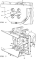
- FIGS 2 to 7 illustrate an alternative embodiment that is functionally similar to the first, except in details of the adjustment mechanism for the part mounting device 22.
- the same reference numerals are otherwise employed where there is a directly correlated function.
- the part mounting device 22 is adjustably attached to the third frame 14 by a series of slotted brackets 25 (also shown in the part view of Figure 6 ).
- Bolt heads 26 provide for tightening or loosening the relative position of the part mounting device 22, including a yaw adjustment if the bolts are set at different relative positions in their respective slots.
- An outwardly tapering blade 27 extending outwardly from the sensor mount apparatus may have foam adhered to it or other means of holding a vehicle part in place for use in testing.
- the outer and largest frame 14 effectively has two extending arms, on the top and at the bottom.
- the frame 14 and these arms control the azimuth tilt (e.g. around H axis) and they include the function, via threaded adjustment, to move the mounted fascia along the F axis (back and forth).
- the shape of the fascia may have a strong free form, such that further mounting elements are needed.
- flexible 3D printed clips that can also take the bent form of complex fascia shapes and be able to fix a position with screws.
- the mounting blades 27 in the second embodiment are preferably 3D printed parts, which may be located into countersinks of the part mount 22. As mentioned, these allow absorber material/foam to be glued in place, which may be important for radar performance test and result authenticity.
- a sensor unit (not shown) may be mounted in use with the mounting plate 11 via an asymmetrical mating shape 28.
- the shape 28 is located on the front side, whereas the rear side of plate 11 is fixed against the robot arm, e.g. via frontally accessed (four) screw pattern 29.
- Mating shape 28 ensures the "Poka-Yoke" position of the radar sensor (not shown) to be fool-proofed so that the axes of the device 10 are assured to go through the radar pivot point.
- the sensor may be mounted to plate 11 by a single screw.
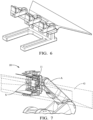
- FIG 7 provides an overview of sensor mounting apparatus 10 in use, as attached to the robotic arm A.
- a radar sensor S is shown in place on plate 11 at the centre of the apparatus, with frames 12, 13 and 14 cascading outwardly from it.
- Sensor S sits behind ghost lines G that represent the field of view of the radar.
- robotic arm A can position sensor S where it is needed, relative to an RTS in an anechoic chamber, and spatially fix it at that position. Then, after initial calibration measurements, a vehicle part can be attached to blades 27 (or brackets 21 of Figure 1 ) and adjusted to any required position relative to the "fixed" sensor S for further measurements to be taken.
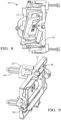
- FIGS. 8 to 10 show a third embodiment of testing apparatus 10, with analogous function to the foregoing embodiments, hence common reference numerals are used.
- FIG. 8 A tilted configuration is shown in Figure 8 , where outer frame 14 has its pitch adjusted (via manual knob 20) relative to mid-frame 13 and the other inner components that are translated in sideways and vertical directions relative to the sensor mount.
- Figure 9 illustrates a variation in execution from previous embodiments in that a yaw adjustment knob 30 is provided for adjusting the angle of a part attachment device 22 relative to the outer frame 14. Furthermore, vehicle attachment features would be affixed to extend forwardly from the device 22 at position 21, i.e. past knob 30. As with other embodiments, a toward and away translational motion for a vehicle part (not shown) relative to a sensor (not shown) is controllable by a threaded member and/or guide rods 24 of the yaw adjustable device 22.
- the invention is generally embodied by a sensor mounting apparatus and associated method, e.g. for use in testing of a vehicle radar sensor in an anechoic chamber.
- the apparatus features a sensor mounting device for mounting the radar sensor and a vehicle part mounting device, e.g. comprised of first, second and third frames.
- Each frame is movable in a different direction relative to the sensor and each other frame, e.g. either adjustable: forward and back, left and right, up and down, and/or via roll, yaw and pitch.
- the outermost frame further includes an attachment means for holding a vehicle part (e.g. a vehicle fascia/bumper) in place and, optionally, provision for further spatial adjustment of the part relative to the sensor in use, e.g. via a pivot mounting enabling yaw movement.
- a vehicle part e.g. a vehicle fascia/bumper
Landscapes
- Engineering & Computer Science (AREA)
- Physics & Mathematics (AREA)
- General Engineering & Computer Science (AREA)
- General Physics & Mathematics (AREA)
- Remote Sensing (AREA)
- Radar, Positioning & Navigation (AREA)
- Mechanical Engineering (AREA)
- Computer Networks & Wireless Communication (AREA)
- Electromagnetism (AREA)
- High Energy & Nuclear Physics (AREA)
- Biochemistry (AREA)
- General Health & Medical Sciences (AREA)
- Immunology (AREA)
- Pathology (AREA)
- Analytical Chemistry (AREA)
- Chemical & Material Sciences (AREA)
- Life Sciences & Earth Sciences (AREA)
- Health & Medical Sciences (AREA)
- Plasma & Fusion (AREA)
- Radar Systems Or Details Thereof (AREA)
- Manipulator (AREA)
Claims (15)
- Eine Sensor-Prüfvorrichtung (10) , umfassend:Sensor-Montageplatte (11) für das Montieren eines Sensors; undFahrzeugteil-Montagevorrichtung für das Montieren eines Fahrzeugteils;wobei die Fahrzeugteil-Montagevorrichtung so konfiguriert ist, dass sie in mindestens drei verschiedene Richtungen im Verhältnis zu der Sensor-Montageplatte beweglich ist, undwobei die Sensor-Prüfvorrichtung dadurch gekennzeichnet ist, dass sich die Fahrzeugteil-Montagevorrichtung von der Sensor-Montageplatte erstreckt.
- Sensor-Prüfvorrichtung nach Anspruch 1, wobei die Fahrzeugteil-Montagevorrichtung eine Vielzahl von Rahmen (12, 12, 14) umfasst und jeder in eine andere Richtung beweglich ist, und die bewegliche Richtung jedes Rahmens ausgewählt ist aus: Vorwärts und Rückwärts, Links und Rechts, Nach oben und Nach unten, Rollen, Gieren und Neigen.
- Sensor-Prüfvorrichtung nach Anspruch 2, wobei die Vielzahl der Rahmen mindestens drei Rahmen (12, 13, 14) umfasst, die so angeordnet sind, dass sie nacheinander von einem größten äußersten Rahmen (14) zu einem kleinsten innersten Rahmen (12) ineinanderpassen, wobei der größte äußerste Rahmen eine Fahrzeugteil-Montagevorrichtung (22) umfasst oder mit Befestigungselementen (21) gekoppelt ist, um sich an einem Fahrzeugteil zu befestigen.
- Sensor-Prüfvorrichtung nach Anspruch 3, wobei die Fahrzeugteil-Montagevorrichtung (22) mindestens ein zusätzliches Positionseinstellelement (24) umfasst, das mit dem äußersten Rahmen (14) gekoppelt ist, um eine relative Position des Fahrzeugteils einzustellen.
- Sensor-Prüfvorrichtung nach Anspruch 4, wobei das mindestens eine zusätzliche Positionseinstellelement Folgendes umfasst: ein Gier-Einstellelement (23, 25) und/oder ein Translations-Einstellelement (24), um das Fahrzeugteil zu und weg von dem Sensor zu bewegen.
- Sensor-Prüfvorrichtung nach Anspruch 5, wobei das Gier-Einstellelement einen Drehzapfen (23) umfasst, der die Fahrzeugteil-Montagevorrichtung mit dem Rahmen koppelt, und/oder das Translations-Einstellelement eine Reihe von Befestigungselementen (26) umfasst, die verschiebbar sind, um eine relative Position innerhalb der Steckplätze (25) oder einem Gewindeelement zu fixieren, um eine relative Bewegung eines Führungselements in einer Schiene zu veranlassen.
- Sensor-Prüfvorrichtung nach einem der vorhergehenden Ansprüche 2 bis 6, wobei der kleinste innerste Rahmen (12) der Vielzahl von Rahmen so konfiguriert ist, dass er eine relative Bewegung in einer vertikalen Richtung im Verhältnis zu der Sensor-Montagevorrichtung (11) ausführt.
- Sensor-Prüfvorrichtung nach einem der vorhergehenden Ansprüche 2 bis 7, wobei ein zweiter Rahmen (13) der Vielzahl von Rahmen so konfiguriert ist, dass er eine relative Bewegung in einer seitlichen Richtung im Verhältnis zu der Sensor-Montagevorrichtung (11) ausführt.
- Sensor-Prüfvorrichtung nach Anspruch 7 oder 8, wobei eine jeweilige Rahmenbewegung in seitlicher und/oder vertikaler Richtung über ein Gewindeelement (16, 18) einstellbar ist.
- Sensor-Prüfvorrichtung nach Anspruch 9, ferner umfassend mindestens zwei Führungsstangen (17, 19), die an einem gegenüber liegenden Rand eines jeweiligen Rahmens positioniert sind, um die Translationsbewegung zu steuern.
- Sensor-Prüfvorrichtung nach einem der vorhergehenden Ansprüche 2 bis 10, wobei der größte äußerste Rahmen (14) der Vielzahl von Rahmen für eine relative Bewegung in eine Kipprichtung im Verhältnis zu einem Antennen-Drehpunkt konfiguriert ist.
- Sensor-Prüfvorrichtung nach einem der vorhergehenden Ansprüche, wobei die Sensor-Montageplatte (11) ein kreisförmiges Lager umfasst, um eine Rollbewegung der Fahrzeugteil-Montagevorrichtung im Verhältnis zu dem Sensor zu ermöglichen.
- Sensor-Prüfvorrichtung nach einem der vorhergehenden Ansprüche, wobei jede der Richtungsbewegungen und/oder Positionseinstellungen motorisiert ist.
- Verfahren zum Montieren eines Fahrzeugteils an einer Sensor-Prüfvorrichtung (10) nach einem der vorhergehenden Ansprüche, umfassend:Montieren des Sensors an der Sensor-Montageplatte;Montieren des Fahrzeugteils an der Fahrzeugteil-Montagevorrichtung und Anordnen des Fahrzeugteils in der Nähe von aber für eine unabhängige Bewegung im Verhältnis zu dem Sensor;wobei die unabhängige relative Bewegung in mindestens drei verschiedene Richtungen eingestellt ist.
- Verfahren nach Anspruch 14, wobei die Sensor-Montageplatte an einem Roboterarm fixiert ist.
Priority Applications (3)
| Application Number | Priority Date | Filing Date | Title |
|---|---|---|---|
| EP22192891.4A EP4332587B1 (de) | 2022-08-30 | 2022-08-30 | Sensormontagevorrichtung für radarprüfung |
| CN202311086755.3A CN117665728A (zh) | 2022-08-30 | 2023-08-24 | 用于雷达测试的传感器安装装置 |
| US18/457,949 US12578213B2 (en) | 2022-08-30 | 2023-08-29 | Sensor mounting device for sensor testing |
Applications Claiming Priority (1)
| Application Number | Priority Date | Filing Date | Title |
|---|---|---|---|
| EP22192891.4A EP4332587B1 (de) | 2022-08-30 | 2022-08-30 | Sensormontagevorrichtung für radarprüfung |
Publications (2)
| Publication Number | Publication Date |
|---|---|
| EP4332587A1 EP4332587A1 (de) | 2024-03-06 |
| EP4332587B1 true EP4332587B1 (de) | 2024-07-24 |
Family
ID=83151862
Family Applications (1)
| Application Number | Title | Priority Date | Filing Date |
|---|---|---|---|
| EP22192891.4A Active EP4332587B1 (de) | 2022-08-30 | 2022-08-30 | Sensormontagevorrichtung für radarprüfung |
Country Status (3)
| Country | Link |
|---|---|
| US (1) | US12578213B2 (de) |
| EP (1) | EP4332587B1 (de) |
| CN (1) | CN117665728A (de) |
Families Citing this family (1)
| Publication number | Priority date | Publication date | Assignee | Title |
|---|---|---|---|---|
| EP4332587B1 (de) * | 2022-08-30 | 2024-07-24 | Aptiv Technologies AG | Sensormontagevorrichtung für radarprüfung |
Family Cites Families (19)
| Publication number | Priority date | Publication date | Assignee | Title |
|---|---|---|---|---|
| US6115261A (en) * | 1999-06-14 | 2000-09-05 | Honeywell Inc. | Wedge mount for integrated circuit sensors |
| DE102004045801B3 (de) * | 2004-09-22 | 2005-12-15 | Daimlerchrysler Ag | Verfahren und Hilfseinrichtung zum Positionieren einer Stütze für ein Messobjekt zum Vermessen mit einem Koordinatenmessgerät |
| US20060065795A1 (en) * | 2004-09-30 | 2006-03-30 | Compx International | Support for flat monitors |
| US7642741B2 (en) * | 2005-04-27 | 2010-01-05 | Sidman Adam D | Handheld platform stabilization system employing distributed rotation sensors |
| US7860651B2 (en) * | 2005-08-30 | 2010-12-28 | Honeywell International Inc. | Enhanced inertial system performance |
| JP6355027B2 (ja) * | 2015-01-23 | 2018-07-11 | 株式会社東京精密 | 形状測定装置 |
| US10455158B2 (en) * | 2015-09-17 | 2019-10-22 | IJK Controls LLC | Stabilized gimbal system with unlimited field of regard |
| JP6767045B2 (ja) * | 2016-11-02 | 2020-10-14 | 株式会社ミツトヨ | 計測用x線ct装置と座標測定機の座標合せ治具 |
| US10883863B2 (en) * | 2017-11-21 | 2021-01-05 | Veoneer Us, Inc. | Interchangeable sensor mounting |
| US10866256B2 (en) * | 2018-07-20 | 2020-12-15 | George V. Zusman | Universal sensor mount |
| CN110398736B (zh) * | 2019-07-04 | 2024-05-24 | 宁波信泰机械有限公司 | 适用acc毫米波标牌的透波性能测试方法及测试设备 |
| CN112013233B (zh) * | 2020-08-06 | 2022-03-25 | 广州科易光电技术有限公司 | 具有多层框架的吊舱的控制方法、装置及电子设备 |
| US12393107B2 (en) * | 2021-03-31 | 2025-08-19 | Honda Motor Co., Ltd. | Camera mounting structure |
| CN113203996B (zh) * | 2021-04-29 | 2025-02-14 | 纵目科技(上海)股份有限公司 | 保险杠对毫米波雷达性能影响的测试方法及其装置与系统 |
| CN113253218B (zh) * | 2021-06-24 | 2024-06-21 | 北京理工大学重庆创新中心 | 一种基于车身定位的毫米波雷达快速定位安装装置及方法 |
| CN215986468U (zh) * | 2021-09-03 | 2022-03-08 | 深圳市蓉声科技有限公司 | 双机械臂整车雷达天线罩测试系统 |
| US11933635B1 (en) * | 2021-10-13 | 2024-03-19 | Worthey Metrology Services, LLC | Sensor mount and components thereof |
| EP4332587B1 (de) * | 2022-08-30 | 2024-07-24 | Aptiv Technologies AG | Sensormontagevorrichtung für radarprüfung |
| US20250137820A1 (en) * | 2023-11-01 | 2025-05-01 | Hellermann Tyton Corporation | Sensor Mount Fixing |
-
2022
- 2022-08-30 EP EP22192891.4A patent/EP4332587B1/de active Active
-
2023
- 2023-08-24 CN CN202311086755.3A patent/CN117665728A/zh active Pending
- 2023-08-29 US US18/457,949 patent/US12578213B2/en active Active
Also Published As
| Publication number | Publication date |
|---|---|
| CN117665728A (zh) | 2024-03-08 |
| US20240068848A1 (en) | 2024-02-29 |
| US12578213B2 (en) | 2026-03-17 |
| EP4332587A1 (de) | 2024-03-06 |
Similar Documents
| Publication | Publication Date | Title |
|---|---|---|
| EP3650817B1 (de) | Hilfskalibriervorrichtung | |
| EP4332587B1 (de) | Sensormontagevorrichtung für radarprüfung | |
| US11305704B2 (en) | Five-axis angular adjustment and azimuth rotation mechanism | |
| US3628862A (en) | Power actuated rearview mirror | |
| JP2002264743A (ja) | 測距センサの取付け構造 | |
| KR20120138617A (ko) | 이동식 센서용 장착부 | |
| US4240596A (en) | Articulated eyeball radome | |
| CN110053564A (zh) | 车辆的外界传感器单元 | |
| US5952980A (en) | Low profile antenna positioning system | |
| WO1989003107A1 (en) | Simulator mechanism | |
| WO2004014720B1 (en) | Accessory device | |
| EP4435386A1 (de) | Sensormontagestation für tests | |
| CN112461359B (zh) | 安装结构以及噪声测试装置 | |
| JP6349870B2 (ja) | レーダアンテナ装置 | |
| JP6361229B2 (ja) | レーダ装置及びその制御方法 | |
| CN217332832U (zh) | 一种传感器集成安装装置和车辆 | |
| EP4467863A1 (de) | Gelenkvorrichtung | |
| US11465562B2 (en) | Vehicle side mirror assembly | |
| US6069756A (en) | Manually-adjustable mirror | |
| CN221300669U (zh) | 角度调节组件及雷达装置 | |
| CN222555168U (zh) | 一种云台挂载雷达及无人机 | |
| GB1578950A (en) | Rear view mirror assembly | |
| CN220400901U (zh) | 小型相控阵雷达天线固定装置 | |
| US12391081B2 (en) | Height sensor and vehicle comprising same | |
| CN216636359U (zh) | 显示屏支架及汽车 |
Legal Events
| Date | Code | Title | Description |
|---|---|---|---|
| PUAI | Public reference made under article 153(3) epc to a published international application that has entered the european phase |
Free format text: ORIGINAL CODE: 0009012 |
|
| STAA | Information on the status of an ep patent application or granted ep patent |
Free format text: STATUS: THE APPLICATION HAS BEEN PUBLISHED |
|
| AK | Designated contracting states |
Kind code of ref document: A1 Designated state(s): AL AT BE BG CH CY CZ DE DK EE ES FI FR GB GR HR HU IE IS IT LI LT LU LV MC MK MT NL NO PL PT RO RS SE SI SK SM TR |
|
| STAA | Information on the status of an ep patent application or granted ep patent |
Free format text: STATUS: REQUEST FOR EXAMINATION WAS MADE |
|
| RAP1 | Party data changed (applicant data changed or rights of an application transferred) |
Owner name: APTIV TECHNOLOGIES AG |
|
| 17P | Request for examination filed |
Effective date: 20240322 |
|
| GRAP | Despatch of communication of intention to grant a patent |
Free format text: ORIGINAL CODE: EPIDOSNIGR1 |
|
| RBV | Designated contracting states (corrected) |
Designated state(s): AL AT BE BG CH CY CZ DE DK EE ES FI FR GB GR HR HU IE IS IT LI LT LU LV MC MK MT NL NO PL PT RO RS SE SI SK SM TR |
|
| STAA | Information on the status of an ep patent application or granted ep patent |
Free format text: STATUS: GRANT OF PATENT IS INTENDED |
|
| RIC1 | Information provided on ipc code assigned before grant |
Ipc: G01S 7/02 20060101ALI20240411BHEP Ipc: G01S 13/931 20200101ALI20240411BHEP Ipc: G01S 7/40 20060101ALI20240411BHEP Ipc: G01M 17/007 20060101ALI20240411BHEP Ipc: F16M 11/24 20060101ALI20240411BHEP Ipc: F16M 11/20 20060101ALI20240411BHEP Ipc: F16M 11/12 20060101ALI20240411BHEP Ipc: F16M 11/08 20060101ALI20240411BHEP Ipc: F16M 11/04 20060101ALI20240411BHEP Ipc: G01R 31/00 20060101ALI20240411BHEP Ipc: G01R 29/08 20060101AFI20240411BHEP |
|
| INTG | Intention to grant announced |
Effective date: 20240502 |
|
| GRAS | Grant fee paid |
Free format text: ORIGINAL CODE: EPIDOSNIGR3 |
|
| GRAA | (expected) grant |
Free format text: ORIGINAL CODE: 0009210 |
|
| STAA | Information on the status of an ep patent application or granted ep patent |
Free format text: STATUS: THE PATENT HAS BEEN GRANTED |
|
| AK | Designated contracting states |
Kind code of ref document: B1 Designated state(s): AL AT BE BG CH CY CZ DE DK EE ES FI FR GB GR HR HU IE IS IT LI LT LU LV MC MK MT NL NO PL PT RO RS SE SI SK SM TR |
|
| REG | Reference to a national code |
Ref country code: GB Ref legal event code: FG4D |
|
| REG | Reference to a national code |
Ref country code: CH Ref legal event code: EP |
|
| P01 | Opt-out of the competence of the unified patent court (upc) registered |
Free format text: CASE NUMBER: APP_40136/2024 Effective date: 20240705 |
|
| REG | Reference to a national code |
Ref country code: IE Ref legal event code: FG4D Ref country code: DE Ref legal event code: R096 Ref document number: 602022004766 Country of ref document: DE |
|
| RAP4 | Party data changed (patent owner data changed or rights of a patent transferred) |
Owner name: APTIV TECHNOLOGIES AG |
|
| REG | Reference to a national code |
Ref country code: LT Ref legal event code: MG9D |
|
| REG | Reference to a national code |
Ref country code: NL Ref legal event code: MP Effective date: 20240724 |
|
| PG25 | Lapsed in a contracting state [announced via postgrant information from national office to epo] |
Ref country code: PT Free format text: LAPSE BECAUSE OF FAILURE TO SUBMIT A TRANSLATION OF THE DESCRIPTION OR TO PAY THE FEE WITHIN THE PRESCRIBED TIME-LIMIT Effective date: 20241125 |
|
| REG | Reference to a national code |
Ref country code: AT Ref legal event code: MK05 Ref document number: 1706780 Country of ref document: AT Kind code of ref document: T Effective date: 20240724 |
|
| PG25 | Lapsed in a contracting state [announced via postgrant information from national office to epo] |
Ref country code: NL Free format text: LAPSE BECAUSE OF FAILURE TO SUBMIT A TRANSLATION OF THE DESCRIPTION OR TO PAY THE FEE WITHIN THE PRESCRIBED TIME-LIMIT Effective date: 20240724 |
|
| PG25 | Lapsed in a contracting state [announced via postgrant information from national office to epo] |
Ref country code: PT Free format text: LAPSE BECAUSE OF FAILURE TO SUBMIT A TRANSLATION OF THE DESCRIPTION OR TO PAY THE FEE WITHIN THE PRESCRIBED TIME-LIMIT Effective date: 20241125 Ref country code: NL Free format text: LAPSE BECAUSE OF FAILURE TO SUBMIT A TRANSLATION OF THE DESCRIPTION OR TO PAY THE FEE WITHIN THE PRESCRIBED TIME-LIMIT Effective date: 20240724 |
|
| PG25 | Lapsed in a contracting state [announced via postgrant information from national office to epo] |
Ref country code: NO Free format text: LAPSE BECAUSE OF FAILURE TO SUBMIT A TRANSLATION OF THE DESCRIPTION OR TO PAY THE FEE WITHIN THE PRESCRIBED TIME-LIMIT Effective date: 20241024 |
|
| PG25 | Lapsed in a contracting state [announced via postgrant information from national office to epo] |
Ref country code: FI Free format text: LAPSE BECAUSE OF FAILURE TO SUBMIT A TRANSLATION OF THE DESCRIPTION OR TO PAY THE FEE WITHIN THE PRESCRIBED TIME-LIMIT Effective date: 20240724 Ref country code: PL Free format text: LAPSE BECAUSE OF FAILURE TO SUBMIT A TRANSLATION OF THE DESCRIPTION OR TO PAY THE FEE WITHIN THE PRESCRIBED TIME-LIMIT Effective date: 20240724 Ref country code: GR Free format text: LAPSE BECAUSE OF FAILURE TO SUBMIT A TRANSLATION OF THE DESCRIPTION OR TO PAY THE FEE WITHIN THE PRESCRIBED TIME-LIMIT Effective date: 20241025 |
|
| PG25 | Lapsed in a contracting state [announced via postgrant information from national office to epo] |
Ref country code: BG Free format text: LAPSE BECAUSE OF FAILURE TO SUBMIT A TRANSLATION OF THE DESCRIPTION OR TO PAY THE FEE WITHIN THE PRESCRIBED TIME-LIMIT Effective date: 20240724 |
|
| PG25 | Lapsed in a contracting state [announced via postgrant information from national office to epo] |
Ref country code: LV Free format text: LAPSE BECAUSE OF FAILURE TO SUBMIT A TRANSLATION OF THE DESCRIPTION OR TO PAY THE FEE WITHIN THE PRESCRIBED TIME-LIMIT Effective date: 20240724 |
|
| PG25 | Lapsed in a contracting state [announced via postgrant information from national office to epo] |
Ref country code: IS Free format text: LAPSE BECAUSE OF FAILURE TO SUBMIT A TRANSLATION OF THE DESCRIPTION OR TO PAY THE FEE WITHIN THE PRESCRIBED TIME-LIMIT Effective date: 20241124 Ref country code: AT Free format text: LAPSE BECAUSE OF FAILURE TO SUBMIT A TRANSLATION OF THE DESCRIPTION OR TO PAY THE FEE WITHIN THE PRESCRIBED TIME-LIMIT Effective date: 20240724 |
|
| PG25 | Lapsed in a contracting state [announced via postgrant information from national office to epo] |
Ref country code: HR Free format text: LAPSE BECAUSE OF FAILURE TO SUBMIT A TRANSLATION OF THE DESCRIPTION OR TO PAY THE FEE WITHIN THE PRESCRIBED TIME-LIMIT Effective date: 20240724 |
|
| PG25 | Lapsed in a contracting state [announced via postgrant information from national office to epo] |
Ref country code: ES Free format text: LAPSE BECAUSE OF FAILURE TO SUBMIT A TRANSLATION OF THE DESCRIPTION OR TO PAY THE FEE WITHIN THE PRESCRIBED TIME-LIMIT Effective date: 20240724 Ref country code: RS Free format text: LAPSE BECAUSE OF FAILURE TO SUBMIT A TRANSLATION OF THE DESCRIPTION OR TO PAY THE FEE WITHIN THE PRESCRIBED TIME-LIMIT Effective date: 20241024 |
|
| PG25 | Lapsed in a contracting state [announced via postgrant information from national office to epo] |
Ref country code: RS Free format text: LAPSE BECAUSE OF FAILURE TO SUBMIT A TRANSLATION OF THE DESCRIPTION OR TO PAY THE FEE WITHIN THE PRESCRIBED TIME-LIMIT Effective date: 20241024 Ref country code: PL Free format text: LAPSE BECAUSE OF FAILURE TO SUBMIT A TRANSLATION OF THE DESCRIPTION OR TO PAY THE FEE WITHIN THE PRESCRIBED TIME-LIMIT Effective date: 20240724 Ref country code: NO Free format text: LAPSE BECAUSE OF FAILURE TO SUBMIT A TRANSLATION OF THE DESCRIPTION OR TO PAY THE FEE WITHIN THE PRESCRIBED TIME-LIMIT Effective date: 20241024 Ref country code: LV Free format text: LAPSE BECAUSE OF FAILURE TO SUBMIT A TRANSLATION OF THE DESCRIPTION OR TO PAY THE FEE WITHIN THE PRESCRIBED TIME-LIMIT Effective date: 20240724 Ref country code: IS Free format text: LAPSE BECAUSE OF FAILURE TO SUBMIT A TRANSLATION OF THE DESCRIPTION OR TO PAY THE FEE WITHIN THE PRESCRIBED TIME-LIMIT Effective date: 20241124 Ref country code: HR Free format text: LAPSE BECAUSE OF FAILURE TO SUBMIT A TRANSLATION OF THE DESCRIPTION OR TO PAY THE FEE WITHIN THE PRESCRIBED TIME-LIMIT Effective date: 20240724 Ref country code: GR Free format text: LAPSE BECAUSE OF FAILURE TO SUBMIT A TRANSLATION OF THE DESCRIPTION OR TO PAY THE FEE WITHIN THE PRESCRIBED TIME-LIMIT Effective date: 20241025 Ref country code: FI Free format text: LAPSE BECAUSE OF FAILURE TO SUBMIT A TRANSLATION OF THE DESCRIPTION OR TO PAY THE FEE WITHIN THE PRESCRIBED TIME-LIMIT Effective date: 20240724 Ref country code: ES Free format text: LAPSE BECAUSE OF FAILURE TO SUBMIT A TRANSLATION OF THE DESCRIPTION OR TO PAY THE FEE WITHIN THE PRESCRIBED TIME-LIMIT Effective date: 20240724 Ref country code: BG Free format text: LAPSE BECAUSE OF FAILURE TO SUBMIT A TRANSLATION OF THE DESCRIPTION OR TO PAY THE FEE WITHIN THE PRESCRIBED TIME-LIMIT Effective date: 20240724 Ref country code: AT Free format text: LAPSE BECAUSE OF FAILURE TO SUBMIT A TRANSLATION OF THE DESCRIPTION OR TO PAY THE FEE WITHIN THE PRESCRIBED TIME-LIMIT Effective date: 20240724 |
|
| PG25 | Lapsed in a contracting state [announced via postgrant information from national office to epo] |
Ref country code: RO Free format text: LAPSE BECAUSE OF FAILURE TO SUBMIT A TRANSLATION OF THE DESCRIPTION OR TO PAY THE FEE WITHIN THE PRESCRIBED TIME-LIMIT Effective date: 20240724 Ref country code: DK Free format text: LAPSE BECAUSE OF FAILURE TO SUBMIT A TRANSLATION OF THE DESCRIPTION OR TO PAY THE FEE WITHIN THE PRESCRIBED TIME-LIMIT Effective date: 20240724 Ref country code: SM Free format text: LAPSE BECAUSE OF FAILURE TO SUBMIT A TRANSLATION OF THE DESCRIPTION OR TO PAY THE FEE WITHIN THE PRESCRIBED TIME-LIMIT Effective date: 20240724 |
|
| PG25 | Lapsed in a contracting state [announced via postgrant information from national office to epo] |
Ref country code: LU Free format text: LAPSE BECAUSE OF NON-PAYMENT OF DUE FEES Effective date: 20240830 |
|
| PG25 | Lapsed in a contracting state [announced via postgrant information from national office to epo] |
Ref country code: MC Free format text: LAPSE BECAUSE OF FAILURE TO SUBMIT A TRANSLATION OF THE DESCRIPTION OR TO PAY THE FEE WITHIN THE PRESCRIBED TIME-LIMIT Effective date: 20240724 Ref country code: EE Free format text: LAPSE BECAUSE OF FAILURE TO SUBMIT A TRANSLATION OF THE DESCRIPTION OR TO PAY THE FEE WITHIN THE PRESCRIBED TIME-LIMIT Effective date: 20240724 |
|
| PG25 | Lapsed in a contracting state [announced via postgrant information from national office to epo] |
Ref country code: CZ Free format text: LAPSE BECAUSE OF FAILURE TO SUBMIT A TRANSLATION OF THE DESCRIPTION OR TO PAY THE FEE WITHIN THE PRESCRIBED TIME-LIMIT Effective date: 20240724 |
|
| REG | Reference to a national code |
Ref country code: DE Ref legal event code: R097 Ref document number: 602022004766 Country of ref document: DE |
|
| PG25 | Lapsed in a contracting state [announced via postgrant information from national office to epo] |
Ref country code: IT Free format text: LAPSE BECAUSE OF FAILURE TO SUBMIT A TRANSLATION OF THE DESCRIPTION OR TO PAY THE FEE WITHIN THE PRESCRIBED TIME-LIMIT Effective date: 20240724 Ref country code: SK Free format text: LAPSE BECAUSE OF FAILURE TO SUBMIT A TRANSLATION OF THE DESCRIPTION OR TO PAY THE FEE WITHIN THE PRESCRIBED TIME-LIMIT Effective date: 20240724 |
|
| PLBE | No opposition filed within time limit |
Free format text: ORIGINAL CODE: 0009261 |
|
| STAA | Information on the status of an ep patent application or granted ep patent |
Free format text: STATUS: NO OPPOSITION FILED WITHIN TIME LIMIT |
|
| REG | Reference to a national code |
Ref country code: BE Ref legal event code: MM Effective date: 20240831 |
|
| 26N | No opposition filed |
Effective date: 20250425 |
|
| PG25 | Lapsed in a contracting state [announced via postgrant information from national office to epo] |
Ref country code: BE Free format text: LAPSE BECAUSE OF NON-PAYMENT OF DUE FEES Effective date: 20240831 |
|
| PG25 | Lapsed in a contracting state [announced via postgrant information from national office to epo] |
Ref country code: IE Free format text: LAPSE BECAUSE OF NON-PAYMENT OF DUE FEES Effective date: 20240830 |
|
| PG25 | Lapsed in a contracting state [announced via postgrant information from national office to epo] |
Ref country code: SE Free format text: LAPSE BECAUSE OF FAILURE TO SUBMIT A TRANSLATION OF THE DESCRIPTION OR TO PAY THE FEE WITHIN THE PRESCRIBED TIME-LIMIT Effective date: 20240724 |
|
| PGFP | Annual fee paid to national office [announced via postgrant information from national office to epo] |
Ref country code: DE Payment date: 20250722 Year of fee payment: 4 |
|
| PGFP | Annual fee paid to national office [announced via postgrant information from national office to epo] |
Ref country code: FR Payment date: 20250812 Year of fee payment: 4 |
|
| PG25 | Lapsed in a contracting state [announced via postgrant information from national office to epo] |
Ref country code: CY Free format text: LAPSE BECAUSE OF FAILURE TO SUBMIT A TRANSLATION OF THE DESCRIPTION OR TO PAY THE FEE WITHIN THE PRESCRIBED TIME-LIMIT; INVALID AB INITIO Effective date: 20220830 |
|
| PG25 | Lapsed in a contracting state [announced via postgrant information from national office to epo] |
Ref country code: HU Free format text: LAPSE BECAUSE OF FAILURE TO SUBMIT A TRANSLATION OF THE DESCRIPTION OR TO PAY THE FEE WITHIN THE PRESCRIBED TIME-LIMIT; INVALID AB INITIO Effective date: 20220830 |
|
| REG | Reference to a national code |
Ref country code: CH Ref legal event code: H13 Free format text: ST27 STATUS EVENT CODE: U-0-0-H10-H13 (AS PROVIDED BY THE NATIONAL OFFICE) Effective date: 20260324 |
|
| PG25 | Lapsed in a contracting state [announced via postgrant information from national office to epo] |
Ref country code: CH Free format text: LAPSE BECAUSE OF NON-PAYMENT OF DUE FEES Effective date: 20250831 |