EP4467863A1 - Gelenkvorrichtung - Google Patents
Gelenkvorrichtung Download PDFInfo
- Publication number
- EP4467863A1 EP4467863A1 EP23175503.4A EP23175503A EP4467863A1 EP 4467863 A1 EP4467863 A1 EP 4467863A1 EP 23175503 A EP23175503 A EP 23175503A EP 4467863 A1 EP4467863 A1 EP 4467863A1
- Authority
- EP
- European Patent Office
- Prior art keywords
- frame
- joint
- movement
- mounting apparatus
- axis
- Prior art date
- Legal status (The legal status is an assumption and is not a legal conclusion. Google has not performed a legal analysis and makes no representation as to the accuracy of the status listed.)
- Pending
Links
Images


Classifications
-
- F—MECHANICAL ENGINEERING; LIGHTING; HEATING; WEAPONS; BLASTING
- F16—ENGINEERING ELEMENTS AND UNITS; GENERAL MEASURES FOR PRODUCING AND MAINTAINING EFFECTIVE FUNCTIONING OF MACHINES OR INSTALLATIONS; THERMAL INSULATION IN GENERAL
- F16H—GEARING
- F16H51/00—Levers of gearing mechanisms
- F16H51/02—Levers of gearing mechanisms adjustable
-
- G—PHYSICS
- G01—MEASURING; TESTING
- G01S—RADIO DIRECTION-FINDING; RADIO NAVIGATION; DETERMINING DISTANCE OR VELOCITY BY USE OF RADIO WAVES; LOCATING OR PRESENCE-DETECTING BY USE OF THE REFLECTION OR RERADIATION OF RADIO WAVES; ANALOGOUS ARRANGEMENTS USING OTHER WAVES
- G01S7/00—Details of systems according to groups G01S13/00, G01S15/00, G01S17/00
- G01S7/02—Details of systems according to groups G01S13/00, G01S15/00, G01S17/00 of systems according to group G01S13/00
- G01S7/40—Means for monitoring or calibrating
-
- F—MECHANICAL ENGINEERING; LIGHTING; HEATING; WEAPONS; BLASTING
- F16—ENGINEERING ELEMENTS AND UNITS; GENERAL MEASURES FOR PRODUCING AND MAINTAINING EFFECTIVE FUNCTIONING OF MACHINES OR INSTALLATIONS; THERMAL INSULATION IN GENERAL
- F16M—FRAMES, CASINGS OR BEDS OF ENGINES, MACHINES OR APPARATUS, NOT SPECIFIC TO ENGINES, MACHINES OR APPARATUS PROVIDED FOR ELSEWHERE; STANDS; SUPPORTS
- F16M11/00—Stands or trestles as supports for apparatus or articles placed thereon ; Stands for scientific apparatus such as gravitational force meters
- F16M11/02—Heads
- F16M11/04—Means for attachment of apparatus; Means allowing adjustment of the apparatus relatively to the stand
- F16M11/06—Means for attachment of apparatus; Means allowing adjustment of the apparatus relatively to the stand allowing pivoting
- F16M11/12—Means for attachment of apparatus; Means allowing adjustment of the apparatus relatively to the stand allowing pivoting in more than one direction
-
- F—MECHANICAL ENGINEERING; LIGHTING; HEATING; WEAPONS; BLASTING
- F16—ENGINEERING ELEMENTS AND UNITS; GENERAL MEASURES FOR PRODUCING AND MAINTAINING EFFECTIVE FUNCTIONING OF MACHINES OR INSTALLATIONS; THERMAL INSULATION IN GENERAL
- F16M—FRAMES, CASINGS OR BEDS OF ENGINES, MACHINES OR APPARATUS, NOT SPECIFIC TO ENGINES, MACHINES OR APPARATUS PROVIDED FOR ELSEWHERE; STANDS; SUPPORTS
- F16M11/00—Stands or trestles as supports for apparatus or articles placed thereon ; Stands for scientific apparatus such as gravitational force meters
- F16M11/02—Heads
- F16M11/04—Means for attachment of apparatus; Means allowing adjustment of the apparatus relatively to the stand
- F16M11/06—Means for attachment of apparatus; Means allowing adjustment of the apparatus relatively to the stand allowing pivoting
- F16M11/12—Means for attachment of apparatus; Means allowing adjustment of the apparatus relatively to the stand allowing pivoting in more than one direction
- F16M11/121—Means for attachment of apparatus; Means allowing adjustment of the apparatus relatively to the stand allowing pivoting in more than one direction constituted of several dependent joints
-
- F—MECHANICAL ENGINEERING; LIGHTING; HEATING; WEAPONS; BLASTING
- F16—ENGINEERING ELEMENTS AND UNITS; GENERAL MEASURES FOR PRODUCING AND MAINTAINING EFFECTIVE FUNCTIONING OF MACHINES OR INSTALLATIONS; THERMAL INSULATION IN GENERAL
- F16M—FRAMES, CASINGS OR BEDS OF ENGINES, MACHINES OR APPARATUS, NOT SPECIFIC TO ENGINES, MACHINES OR APPARATUS PROVIDED FOR ELSEWHERE; STANDS; SUPPORTS
- F16M11/00—Stands or trestles as supports for apparatus or articles placed thereon ; Stands for scientific apparatus such as gravitational force meters
- F16M11/02—Heads
- F16M11/18—Heads with mechanism for moving the apparatus relatively to the stand
-
- F—MECHANICAL ENGINEERING; LIGHTING; HEATING; WEAPONS; BLASTING
- F16—ENGINEERING ELEMENTS AND UNITS; GENERAL MEASURES FOR PRODUCING AND MAINTAINING EFFECTIVE FUNCTIONING OF MACHINES OR INSTALLATIONS; THERMAL INSULATION IN GENERAL
- F16M—FRAMES, CASINGS OR BEDS OF ENGINES, MACHINES OR APPARATUS, NOT SPECIFIC TO ENGINES, MACHINES OR APPARATUS PROVIDED FOR ELSEWHERE; STANDS; SUPPORTS
- F16M13/00—Other supports for positioning apparatus or articles; Means for steadying hand-held apparatus or articles
- F16M13/02—Other supports for positioning apparatus or articles; Means for steadying hand-held apparatus or articles for supporting on, or attaching to, an object, e.g. tree, gate, window-frame, cycle
-
- G—PHYSICS
- G01—MEASURING; TESTING
- G01S—RADIO DIRECTION-FINDING; RADIO NAVIGATION; DETERMINING DISTANCE OR VELOCITY BY USE OF RADIO WAVES; LOCATING OR PRESENCE-DETECTING BY USE OF THE REFLECTION OR RERADIATION OF RADIO WAVES; ANALOGOUS ARRANGEMENTS USING OTHER WAVES
- G01S7/00—Details of systems according to groups G01S13/00, G01S15/00, G01S17/00
- G01S7/02—Details of systems according to groups G01S13/00, G01S15/00, G01S17/00 of systems according to group G01S13/00
- G01S7/40—Means for monitoring or calibrating
- G01S7/4052—Means for monitoring or calibrating by simulation of echoes
- G01S7/4082—Means for monitoring or calibrating by simulation of echoes using externally generated reference signals, e.g. via remote reflector or transponder
- G01S7/4086—Means for monitoring or calibrating by simulation of echoes using externally generated reference signals, e.g. via remote reflector or transponder in a calibrating environment, e.g. anechoic chamber
Definitions
- the present disclosure relates to a joint device, particularly for use in a multi-axis motion fixture, relevant to testing of vehicular sensor units.
- Modern vehicles which possess autonomous driving functionality require precise sensing of their immediate environment and beyond to be operated safely. This is often achieved by a variety of sensors, such as one or more radar sensors that are mounted to the vehicle body, e.g. behind a fascia element such as a vehicle bumper.
- sensors such as one or more radar sensors that are mounted to the vehicle body, e.g. behind a fascia element such as a vehicle bumper.
- Testing is undertaken in an isolated environment (e.g. anechoic chamber) where there is good control over target size and other parameters (speed, amplitude, position) to verify radar performance over mechanical tolerances of assembly and to fulfil functional requirements in terms of accuracy and detection range/ability.
- anechoic chamber e.g. anechoic chamber
- radar sensor tests may be performed by mounting a sensor to a robotic arm and further mounting the fascia in front of the sensor, with a positioning device for setting the distance between radar and fascia.
- the test method typically involves the radar sensor unit, mounted on the robotic arm, being moved completely (e.g. azimuth elevation, translation x, y, z) within the range of field of view of the radar to measure the radar detection parameters with the fascia in place.
- the test is repeated with/without fascia to measure signal degradation.
- the positioning device may include several joints to articulate movement.
- joint types are available that may be integrated into the design of the sensor mounting unit. For example, a joint may be needed between a linear actuator at a base frame and a frame that is to be moved about several axes.
- Known joint types include cross or universal joints, hinges and ball joints.
- a joint device e.g. for use with a multiple axis motion fixture, comprising: a first end portion for coupling to a linear actuator; a connector portion; and a second end portion for coupling to a rotatably moveable object; wherein the first end portion is pivotably attached to a proximate end of the connector portion about a pivot having one axis of movement, being a first axis, and the second end portion is pivotably attached to a distal end of the connector portion about a pivot having at least two axes of movement, being a second axis and third axis respectively.
- the second axis can be parallel to the first axis and the third axis perpendicular to the first and second axes.
- the device enables a translation of linear motion, e.g. from the linear actuator, into rotary motion while also allowing for the rotation of an axis.
- prior art devices with a similar function were not able to hold a constant rotation point, including trial of a double Cardan joint, where two universal joints are joined by an intermediate shaft.
- the second and third axes intersect. In this way, the second and third axes form a cross joint, such as found in a universal joint.
- the connector portion is a rigid rod/shaft.
- one joint device enables the translation of linear motion into rotation. With the use of two actuators and joints, rotation around two axes with a fixed pivot point is achievable. Adding a third joint allows for rotation around two axes with a constant pivot point, as well as movement in the z-axis direction. This configuration is useful for implementation in a multiple (i.e. up to six)-axis motion fixture for testing of automotive sensors.
- the joint device may also be considered a hybrid joint comprising: a first shaft/part; a second shaft/part; and a third shaft/part; wherein the first shaft is pivotably connected to a proximate end of the second shaft by a hinge having one axis of movement, and the third shaft is pivotably connected to a distal end of the second shaft by a joint having two axes of movement.
- one of the two axes of movement of the third shaft is parallel to the one axis of movement of the hinge.
- the other axis may be perpendicular.
- the hinge connection between the first and second shaft comprises a first yoke and a pivot pin.
- the pivotal connection between the second and third shafts comprises two mating yokes and a cross member.
- the connection is a universal joint enabling relative movement of the second and third shafts about two axes.
- a universal joint is designed to transmit torque between two shafts that are not necessarily aligned with each other.
- the cross member allows the shafts to rotate relative to each other, while trunnions provide a smooth and efficient transmission of torque.
- the transmission device of the invention may be considered a shaft incorporating two joints, a first joint enabling only one freedom of movement about a first axis and a second joint enabling freedom of movement about second and third axes.
- the third axis may be perpendicular to the first two axes.
- the second joint could be comprised of two joint portions, respectively pivotable about the second and third axes.
- the shafts/portions may be made of steel or another suitable strong cast or machined material.
- the invention facilitates, in addition to mounting of the sensor, more flexibility and control for verification tests via a mount system for the vehicle part that moves independently from the sensor. Particularly, it may provide a manual and accurate control of fascia (i.e. the vehicle part) position against the sensor (e.g. radar)
- fascia i.e. the vehicle part
- the sensor e.g. radar
- any problems of weight, manual control and cost are solved by an assembly of simple joint devices that can be made from light materials such as aluminium and plastic. It is possible to automate, by servo motors or the like, relative movement of the mounting system and joint devices.
- provision may be made for movement of the vehicle part (e.g. fascia, bumper, etc) and/or sensor mount in any direction including pitch, yaw, roll, i.e. up to six degrees of freedom including three translational motions and three rotational motions.
- the classic example of movement in three-dimensional space can entail translational movements forward and back, left and right, and up and down; and rotational movement about the X, Y, and Z axes (defining roll, yaw and pitch respectively).
- a sensor is mounted to a sensor mount that is in turn connected to a robotic arm.
- a method of use is performed in the context of testing properties of a radar sensor when the vehicle part is disposed between it and a radar target simulator.
- a mounting apparatus may comprising: a first frame; a second frame (either of which could be alternatively termed “a bracket”); and at least two joint devices, as described herein, wherein each joint device is coupled at one end to a linear actuator extending from the second frame toward the first frame and coupled at the other end to the first frame; so that extension of a linear actuator is able to cause movement such as tilting yaw/pitch movement, through a joint device, of the first frame relative to the second frame.
- the term “comprising” as used in this specification means “consisting at least in part of” such that interpreting each statement in this specification that includes the term “comprising”, features other than that or those prefaced by the term may also be present.
- Related terms such as “comprise” and “comprises” are to be interpreted in the same manner.
- Directional terms such as “vertical”, “horizontal”, “up”, “down”, “sideways”, “upper” and “lower” are used for convenience of explanation usually with reference to the orientation shown in illustrations and are not intended to be ultimately limiting if an equivalent function can be achieved with an alternative dimension and/or direction. Indeed, in the present case a term such as “horizontal” axis or “vertical” axis can be affected by the orientation imposed on the sensor mounting structure by the robotic arm. Therefore, all directional terms are relative to each other.
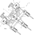
- FIGS 1 and 2 provide an overview of a sensor mounting apparatus 10 suitable for testing a sensor, e.g. in an anechoic chamber.
- the apparatus may comprise a mounting frame 12, including an inset cradle 13 for receiving a sensor (not visible) to be mounted.
- Frame 12/cradle 13 is ultimately mounted for tilting movement about axes A-A and B-B relative to a base frame 14, by virtue of three joint devices 15 according to the invention.
- Each joint device provides a transmission/connection/interface for a linear actuator 16, to control tilting of the sensor mount/frame 12.
- the apparatus as shown enables, through the linear actuators 16, tilting of the sensor mount about two axes and translational movement in a z-direction, toward and away from base frame 14.
- a further x-y positioning device may be located behind the fixture/base 14 for a further two degrees of movement, along with a sixth, roll, axis.
- a first shaft or end portion 21, for connection to a linear actuator 16 (such as by a bearing interfacing with the screw thread of the actuator), is coupled to the yoke 22 of a second shaft 23 by a pivot pin 24 corresponding to a first pivot axis D-D.
- a first joint/hinge in the shaft/device limited to one degree of movement only. Any force urging the shaft to bend in a direction coincident to D-D is inherently resisted.
- the second shaft 23 is coupled to a third shaft 25 by a two-way joint, e.g. a universal joint or cross joint, where inter-engaging yokes 26 are secured by an internal cross member/pins 27.
- a second pivot axis E- E, defined by the cross member 27, is parallel to D-D, whereas a third pivot axis F-F of the device is perpendicular as defined by the cross member.
- the two-way connection provides a second joint in the shaft/device as a whole with two degrees of movement, preferably limited to two degrees of movement only.
- the third shaft 25 is configured for a fixed connection to an object to be articulated, e.g. the sensor mount frame 12.
- the combined shaft portions 21, 23 and 25, as illustrated, are alignable along a straight line, longitudinal axis. However, the sections are able to deviate from alignment subject to the degrees of movement allowed by the hinge and universal joint.
- a hinged elbow one degree of movement
- a ball joint providing at least two degrees of movement
- a yoke-type joint as illustrated may rotate beyond 180 degrees and up to, say, 270 degrees or more.
- Figures 4 and 5 illustrate the two joints of device 15 in use, where the device is connected at one end to a linear actuator 28 and serves as a bridge to connect to a second object 29.
- Object 29 is able to rotate around a rotation point 30 using the linear motion of the actuator 28. This design ensures that any change in the y-axis distance between the centre axis linear actuator 28 and the connection point 31 to the second object 29 is balanced.
- the bearing of the second object 29 may also enable rotation around its centre axis.
- Figures 6 to 9 illustrate use of the joint device 15 in the context of the sensor mount apparatus 10 of Figures 1 and 2 .
- no tilt pitch/yaw of the frame 12 is yet implemented relative to a joint axis.
- a z-direction adjustment may be achieved by extending each actuator by the same amount, thereby displacing frame 12 from base 14.
- a tilted pitch is achievable about axis B-B from Figure 1 , e.g. relative to an antenna pivot point, that is the antenna (not shown) middle point, the position of which is needed for measurements to be taken during testing, by variously extending/retracting the actuators 16 as desired.
- the antenna pivot point may generally correspond to the intersection of axes A-A and B-B from Figure 1 .
- a yaw tilt is achievable about axis A-A from Figure 1 by extending/retracting linear actuators 16 and thereby reconfiguring the frame 12 position relative to base frame 15.
- the invention is generally embodied by a joint device for use with a mounting apparatus, such as used in vehicle sensor testing.
- the device comprises a first end section, a second intermediate connector section and a third end section, wherein a joint is provided between each section.
- a hinge joint having one axis of movement connects the first and second sections, while a cross joint connects the second and third sections, enabling two axes of movement.
- At least two, preferably three, of the joint devices are assembled into a mounting apparatus that has a first frame moveable relative to a second frame by linear actuators.
- the joint devices enable controlled tilting of the first frame about yaw and pitch axes, and also translational movement in z-direction by activating the linear actuators.
Landscapes
- Engineering & Computer Science (AREA)
- General Engineering & Computer Science (AREA)
- Mechanical Engineering (AREA)
- Computer Networks & Wireless Communication (AREA)
- Physics & Mathematics (AREA)
- General Physics & Mathematics (AREA)
- Radar, Positioning & Navigation (AREA)
- Remote Sensing (AREA)
- Manipulator (AREA)
Priority Applications (3)
| Application Number | Priority Date | Filing Date | Title |
|---|---|---|---|
| EP23175503.4A EP4467863A1 (de) | 2023-05-25 | 2023-05-25 | Gelenkvorrichtung |
| CN202410567091.0A CN119022189A (zh) | 2023-05-25 | 2024-05-09 | 接头装置 |
| US18/666,899 US20240392868A1 (en) | 2023-05-25 | 2024-05-17 | Joint Device |
Applications Claiming Priority (1)
| Application Number | Priority Date | Filing Date | Title |
|---|---|---|---|
| EP23175503.4A EP4467863A1 (de) | 2023-05-25 | 2023-05-25 | Gelenkvorrichtung |
Publications (1)
| Publication Number | Publication Date |
|---|---|
| EP4467863A1 true EP4467863A1 (de) | 2024-11-27 |
Family
ID=86605220
Family Applications (1)
| Application Number | Title | Priority Date | Filing Date |
|---|---|---|---|
| EP23175503.4A Pending EP4467863A1 (de) | 2023-05-25 | 2023-05-25 | Gelenkvorrichtung |
Country Status (3)
| Country | Link |
|---|---|
| US (1) | US20240392868A1 (de) |
| EP (1) | EP4467863A1 (de) |
| CN (1) | CN119022189A (de) |
Citations (3)
| Publication number | Priority date | Publication date | Assignee | Title |
|---|---|---|---|---|
| CN103423558A (zh) * | 2013-07-16 | 2013-12-04 | 燕山大学 | 一种耦合型四自由度并联隔振平台 |
| US10837402B2 (en) * | 2020-01-09 | 2020-11-17 | Guanhao Wu | Thrust vector nozzle |
| US11548339B2 (en) * | 2018-08-01 | 2023-01-10 | Schaeffler Technologies AG & Co. KG | Relative guide device for a steering arrangement arranged on the wheel-carrier side |
-
2023
- 2023-05-25 EP EP23175503.4A patent/EP4467863A1/de active Pending
-
2024
- 2024-05-09 CN CN202410567091.0A patent/CN119022189A/zh active Pending
- 2024-05-17 US US18/666,899 patent/US20240392868A1/en active Pending
Patent Citations (3)
| Publication number | Priority date | Publication date | Assignee | Title |
|---|---|---|---|---|
| CN103423558A (zh) * | 2013-07-16 | 2013-12-04 | 燕山大学 | 一种耦合型四自由度并联隔振平台 |
| US11548339B2 (en) * | 2018-08-01 | 2023-01-10 | Schaeffler Technologies AG & Co. KG | Relative guide device for a steering arrangement arranged on the wheel-carrier side |
| US10837402B2 (en) * | 2020-01-09 | 2020-11-17 | Guanhao Wu | Thrust vector nozzle |
Also Published As
| Publication number | Publication date |
|---|---|
| CN119022189A (zh) | 2024-11-26 |
| US20240392868A1 (en) | 2024-11-28 |
Similar Documents
| Publication | Publication Date | Title |
|---|---|---|
| KR100494232B1 (ko) | 로봇의 캘리브레이션 장치 및 방법 | |
| US6145405A (en) | Coordinate positioning machine | |
| EP0066393B1 (de) | Mehrarmiger Roboter | |
| KR102309861B1 (ko) | 6축 로봇의 자세 조정 방법 | |
| US20220401168A1 (en) | Slave Device and Control Method Therefor, and Eye Surgery Device and Control Method Therefor | |
| CN106840583A (zh) | 一种具有平移功能的亚跨超声速风洞大攻角机构 | |
| JP2000512558A (ja) | 製品位置決めシステム | |
| WO2026037149A1 (zh) | 用于自动充电的三轴并联旋转机构及其控制方法 | |
| JP3435448B2 (ja) | 風洞模型支持装置およびそれを用いた風洞試験装置 | |
| JP4256205B2 (ja) | 風洞模型支持装置 | |
| CN113246102B (zh) | 一种具有可变柔度方向的刚柔耦合装置和一种机械臂 | |
| JPH0246357B2 (de) | ||
| KR100880290B1 (ko) | 헥사포드 터렛의 이동판을 변위시키는 방법 및 장치 | |
| US20240392868A1 (en) | Joint Device | |
| JPH0657394B2 (ja) | ア−ム装置 | |
| EP4332587B1 (de) | Sensormontagevorrichtung für radarprüfung | |
| JPH01183384A (ja) | 水平多関節型ロボットのロボット腕構造 | |
| CN113169439A (zh) | 铰接机构和包括所述机构的铰接指向系统 | |
| EP4435386A1 (de) | Sensormontagestation für tests | |
| CN224255346U (zh) | 头部结构和机器人 | |
| CN224255347U (zh) | 头部结构和机器人 | |
| CN120350825B (zh) | 一种串并联混合的电液混合臂架系统及混凝土泵车 | |
| CN114930797B (zh) | 自动驾驶视觉标定装置 | |
| JPS6327113B2 (de) | ||
| CN119683025B (zh) | 一种航天器机构展开试验自动装调方法及装调系统 |
Legal Events
| Date | Code | Title | Description |
|---|---|---|---|
| PUAI | Public reference made under article 153(3) epc to a published international application that has entered the european phase |
Free format text: ORIGINAL CODE: 0009012 |
|
| STAA | Information on the status of an ep patent application or granted ep patent |
Free format text: STATUS: THE APPLICATION HAS BEEN PUBLISHED |
|
| AK | Designated contracting states |
Kind code of ref document: A1 Designated state(s): AL AT BE BG CH CY CZ DE DK EE ES FI FR GB GR HR HU IE IS IT LI LT LU LV MC ME MK MT NL NO PL PT RO RS SE SI SK SM TR |
|
| STAA | Information on the status of an ep patent application or granted ep patent |
Free format text: STATUS: REQUEST FOR EXAMINATION WAS MADE |
|
| 17P | Request for examination filed |
Effective date: 20241218 |
|
| STAA | Information on the status of an ep patent application or granted ep patent |
Free format text: STATUS: EXAMINATION IS IN PROGRESS |
|
| 17Q | First examination report despatched |
Effective date: 20260122 |