EP4332832A1 - Localisation d'un code optique - Google Patents
Localisation d'un code optique Download PDFInfo
- Publication number
- EP4332832A1 EP4332832A1 EP22193715.4A EP22193715A EP4332832A1 EP 4332832 A1 EP4332832 A1 EP 4332832A1 EP 22193715 A EP22193715 A EP 22193715A EP 4332832 A1 EP4332832 A1 EP 4332832A1
- Authority
- EP
- European Patent Office
- Prior art keywords
- search pattern
- edge transitions
- code
- image
- search
- Prior art date
- Legal status (The legal status is an assumption and is not a legal conclusion. Google has not performed a legal analysis and makes no representation as to the accuracy of the status listed.)
- Granted
Links
Images


Classifications
-
- G—PHYSICS
- G06—COMPUTING OR CALCULATING; COUNTING
- G06K—GRAPHICAL DATA READING; PRESENTATION OF DATA; RECORD CARRIERS; HANDLING RECORD CARRIERS
- G06K7/00—Methods or arrangements for sensing record carriers, e.g. for reading patterns
- G06K7/10—Methods or arrangements for sensing record carriers, e.g. for reading patterns by electromagnetic radiation, e.g. optical sensing; by corpuscular radiation
- G06K7/14—Methods or arrangements for sensing record carriers, e.g. for reading patterns by electromagnetic radiation, e.g. optical sensing; by corpuscular radiation using light without selection of wavelength, e.g. sensing reflected white light
- G06K7/1404—Methods for optical code recognition
- G06K7/1439—Methods for optical code recognition including a method step for retrieval of the optical code
- G06K7/1443—Methods for optical code recognition including a method step for retrieval of the optical code locating of the code in an image
-
- G—PHYSICS
- G06—COMPUTING OR CALCULATING; COUNTING
- G06K—GRAPHICAL DATA READING; PRESENTATION OF DATA; RECORD CARRIERS; HANDLING RECORD CARRIERS
- G06K7/00—Methods or arrangements for sensing record carriers, e.g. for reading patterns
- G06K7/10—Methods or arrangements for sensing record carriers, e.g. for reading patterns by electromagnetic radiation, e.g. optical sensing; by corpuscular radiation
- G06K7/10544—Methods or arrangements for sensing record carriers, e.g. for reading patterns by electromagnetic radiation, e.g. optical sensing; by corpuscular radiation by scanning of the records by radiation in the optical part of the electromagnetic spectrum
- G06K7/10821—Methods or arrangements for sensing record carriers, e.g. for reading patterns by electromagnetic radiation, e.g. optical sensing; by corpuscular radiation by scanning of the records by radiation in the optical part of the electromagnetic spectrum further details of bar or optical code scanning devices
- G06K7/10861—Methods or arrangements for sensing record carriers, e.g. for reading patterns by electromagnetic radiation, e.g. optical sensing; by corpuscular radiation by scanning of the records by radiation in the optical part of the electromagnetic spectrum further details of bar or optical code scanning devices sensing of data fields affixed to objects or articles, e.g. coded labels
-
- G—PHYSICS
- G06—COMPUTING OR CALCULATING; COUNTING
- G06K—GRAPHICAL DATA READING; PRESENTATION OF DATA; RECORD CARRIERS; HANDLING RECORD CARRIERS
- G06K7/00—Methods or arrangements for sensing record carriers, e.g. for reading patterns
- G06K7/10—Methods or arrangements for sensing record carriers, e.g. for reading patterns by electromagnetic radiation, e.g. optical sensing; by corpuscular radiation
- G06K7/14—Methods or arrangements for sensing record carriers, e.g. for reading patterns by electromagnetic radiation, e.g. optical sensing; by corpuscular radiation using light without selection of wavelength, e.g. sensing reflected white light
- G06K7/1404—Methods for optical code recognition
- G06K7/1408—Methods for optical code recognition the method being specifically adapted for the type of code
- G06K7/1417—2D bar codes
-
- G—PHYSICS
- G06—COMPUTING OR CALCULATING; COUNTING
- G06K—GRAPHICAL DATA READING; PRESENTATION OF DATA; RECORD CARRIERS; HANDLING RECORD CARRIERS
- G06K7/00—Methods or arrangements for sensing record carriers, e.g. for reading patterns
- G06K7/10—Methods or arrangements for sensing record carriers, e.g. for reading patterns by electromagnetic radiation, e.g. optical sensing; by corpuscular radiation
- G06K7/14—Methods or arrangements for sensing record carriers, e.g. for reading patterns by electromagnetic radiation, e.g. optical sensing; by corpuscular radiation using light without selection of wavelength, e.g. sensing reflected white light
- G06K7/1404—Methods for optical code recognition
- G06K7/146—Methods for optical code recognition the method including quality enhancement steps
-
- G—PHYSICS
- G06—COMPUTING OR CALCULATING; COUNTING
- G06T—IMAGE DATA PROCESSING OR GENERATION, IN GENERAL
- G06T7/00—Image analysis
- G06T7/10—Segmentation; Edge detection
- G06T7/13—Edge detection
-
- G—PHYSICS
- G06—COMPUTING OR CALCULATING; COUNTING
- G06V—IMAGE OR VIDEO RECOGNITION OR UNDERSTANDING
- G06V30/00—Character recognition; Recognising digital ink; Document-oriented image-based pattern recognition
- G06V30/10—Character recognition
- G06V30/22—Character recognition characterised by the type of writing
- G06V30/224—Character recognition characterised by the type of writing of printed characters having additional code marks or containing code marks
Definitions
- the invention relates to a method for locating an optical code according to the preamble of claim 1.
- Code readers are known from supermarket checkouts, for automatic package identification, sorting of mail, baggage handling in airports and other logistics applications.
- a reading beam is guided across the code using a rotating mirror or a polygon mirror wheel.
- a camera-based code reader uses an image sensor to take images of the objects with the codes on them, and image evaluation software extracts the code information from these images.
- a scanning code reader records the codes that are brought into its reading area one after the other.
- a line camera reads the object images with the code information successively and line by line with the relative movement.
- a two-dimensional image sensor is used to regularly record image data, which overlap more or less depending on the recording frequency and conveyor speed. So that the objects can be arranged in any orientation on the conveyor, several code readers are often provided on a reading tunnel in order to pick up objects from several or all sides.
- a scanning code reader also records the remission and thus ultimately image lines that can be combined to form an object image, even if an image sensor is preferred for this in practice. In such an object image, code areas can be identified and codes can be read.
- Decoding is a relatively complex process. Therefore, only those image sections in which an optical code has been recognized through preprocessing are usually fed to a decoder, preferably with further information such as the exact position and orientation as well as the type and size of the code.
- Some types of code support localization using finder patterns that can be easily and robustly recognized.
- a QR code for example, has search patterns in three corners, an Aztec code has one in the center.
- the search pattern itself consists of 7x7 code modules with a 3x3 field in the middle surrounded by two alternating rings or rectangles.
- the US 9,355,293 B2 discloses a system for recognizing and decoding QR codes that creates a template for pattern matching in order to find search patterns and thus the code.
- This object is achieved by a method for locating an optical code and an optoelectronic code reading device with the method according to claim 1 or 15 implemented therein.
- this is an automatic, in particular computer-implemented, method that runs, for example, in a code reader or a computing device connected to it, such as a control device, a computer, an edge device, a network or a cloud.
- An image is captured which presumably contains at least one optical code, in particular a QR code or an Aztec code. As explained in the introduction, this can be done in one shot or successively during a relative movement, whereby the brightness profiles of a code scanner can also be viewed as one image line.
- the image has a plurality of pixels, typically a pixel grid of m ⁇ n pixels.
- the code is located using at least one search pattern (Finder Pattern).
- Finder Pattern search pattern
- a candidate position is determined which, at least at first glance, is part of a search pattern.
- edge transitions are determined along at least one line through the image.
- the transition between a dark and a light code element or, conversely, between a light and a dark code element is called an edge.
- the code elements are only actually black and white in a binarized image; otherwise, for simplicity, no distinction is made between white and light gray tones or black and dark gray tones.
- the line preferably follows the row direction or column direction. Other directions are also possible in principle, but the implementation becomes more complex and discretization artifacts can arise.
- the position of the search pattern is then determined in an area surrounding the candidate position.
- the candidate position is still quite rough, for example a single person Point approximately in the assumed middle of the search pattern.
- the position of the search pattern indicates which pixels belong to the search pattern, for example in the form of a frame around the search pattern.
- the concrete representation for example as a corner or surrounding square, is not important and is not fixed.
- the invention is based on the basic idea of verifying the search pattern that has already been found and its position again.
- location of the search pattern for example a frame
- its properties such as module size down to individual code modules can be checked.
- a code module, or module for short is the smallest element of the code.
- the module size is specified as a measure of the expansion of the module in pixels per module (ppm). Since it is completely known what a search pattern must look like, further properties of the search pattern to be verified can be checked that have not yet been used, at least in this form, to locate it, or a test step can be carried out that was not used to find the location .
- the invention has the advantage that the error rate when locating search patterns and ultimately optical codes is reduced. Somewhat more generous search patterns can be detected, including partially obscured search patterns or those where edge detection sporadically fails, for example due to a lack of contrast. This means that search patterns are rarely overlooked. The verification ensures that initially incorrectly accepted search patterns are ultimately correctly rejected. Overall, the rate of type I and type II errors is low, or, to put it positively, both the sensitivity and specificity of the recognition of search patterns and thus codes are very high. Simple geometric operations with only a few accesses to the pixels of the image are sufficient, so that the method works efficiently and quickly and remains capable of real-time or only takes up a small proportion of the short time windows that are available for decoding in a reading tunnel. Almost all (sensitivity) codes are fed to the decoder very quickly, without having to spend computing time on image areas that actually contain no code at all (specificity). This increases the read rate and thus the most important quality criterion of a code reading application.
- a candidate position is preferably determined if the edge transitions along the at least one line take into account a tolerance distances in relation 1:1:3:1:1 to each other.
- a special feature of this search pattern is that these distance relationships exist in every direction, and therefore completely independent of the orientation of the code, even for a line in any given direction, especially in the line direction of the image. In a real image, the distance conditions cannot be expected exactly, so a tolerance is preferably allowed.
- the candidate position is preferably determined as the center of gravity of edge transitions along the at least one line.
- the candidate position should be as central as possible in the search pattern, and this is achieved by creating this focus in the direction of the line. In any case, the center of the search pattern cannot be far away, otherwise the condition of edge transitions in the direction of the line would not be fulfilled. In particular, distance ratios of 1:1:3:1:1 only exist for lines through the central 3x3 field of the search pattern. There are various options for calculating the center of gravity, for example as the middle between the two outermost edge transitions or as the average of all edge transitions.
- the candidate position is preferably determined in the middle between the parallel lines.
- Several adjacent, mutually parallel lines can have edge transitions that indicate the crossing of a search pattern, in particular the distance ratio of 1:1:3:1:1 between the edge transitions.
- the center of the search pattern is then expected to be on the middle line or, if the number of affected lines is even, between the two middle lines. This center can be found in two steps by first determining, as in the previous paragraph, a center of gravity for each line and then a center of gravity of the centers of gravity transverse to the direction of the line. However, the calculation can be carried out in any way, for example as the center of gravity of all edge transitions of the affected lines or only the outermost edge transitions or lines.
- the next three edge transitions are preferably determined along rays emanating in a star shape from the candidate position, in particular along eight or sixteen rays at the same angular distance from one another.
- the candidate position was initially only found using lines of the same direction, especially the line direction.
- the star-shaped rays now localize the search pattern more precisely in all directions. Eight directions with a mutual angular offset of 45° each or sixteen directions with a mutual angular offset of 22.5° are preferably used. An even narrower angular grid would be too complex without any noticeable improvement. An uneven angular grid is conceivable, but it makes the silent and unwarranted assumption that some directions are more important.
- a uniform subdivision with a different number of rays, for example seven rays, has the disadvantage that the gradient of the rays is no longer a simple value such as 1 ⁇ 2, 1 or 2 and discretization errors therefore occur. If the candidate position is actually halfway in the middle of a search pattern, the next three edge transitions lead through the two surrounding rectangular rings. As an optional step, it can be checked whether the distances between the edge transitions in all or at least most directions are plausible with the crossing of two rectangular rings.
- the respective first edge transitions of the beams are preferably connected to form a first ring, the respective second edge transitions of the beams to form a second ring and/or the respective third edge transitions to form a third ring.
- These rings form the previously estimated approximation to the edges between the center and the rectangular rings of the search pattern.
- Confirmed ring sections of the rings that run along an edge are preferably determined, in particular with the aid of a Sobel filter.
- the edge transitions along the rays may in reality not correspond to rectangular rings of a search pattern for various reasons, for example because there is no search pattern at the candidate position, because an edge transition along a ray is hidden, has poor contrast, or with the set criteria for an edge transition was overlooked. It therefore makes sense to carry out an additional check to see whether a ring section really runs along an edge of a search pattern.
- the three rings are thereby divided into confirmed and unconfirmed ring sections, and preferably only the confirmed ring sections are continued. If there are no confirmed or too few confirmed ring sections, the procedure for this candidate position can be aborted.
- a preferred way to confirm ring sections is to use a Sobel filter.
- Ring sections of the rings are preferably classified into horizontal and vertical ring sections, and an orientation of the search pattern is determined from this.
- the ring sections are based on the connecting lines between the edge transitions on the star-shaped rays from the candidate position. If they actually run along the edges between the center and the rectangular rings of a search pattern, they only have two orientations corresponding to the main horizontal and vertical directions of the search pattern. At least approximately this also applies to the ring sections found, which are clustered accordingly in order to find these two main directions.
- the main directions are then defined, for example, as the mean orientation of the ring sections of the respective cluster. All ring sections can be used or preferably only confirmed ring sections and/or, for example, only ring sections of a ring, such as the third, outermost ring.
- An outermost ring section is preferably selected in each of the four main directions according to the orientation, with straight lines along the ring sections framing the position of the search pattern. Once the orientation of the search pattern has been determined, the four main directions "up”, “down”, “right” and “left” are defined in a coordinate system tied to these orientations. An outermost ring section is now sought in each of these main directions, preferably a confirmed ring section of the third ring. Straight lines through these ring sections now form a frame around the search pattern, which is thus localized.
- the missing outermost ring section is preferably reconstructed from other ring sections using the known structure of a search pattern. It may be that the search pattern is obscured or has too low contrast in a main direction, or that for other reasons no outermost ring section can be found in this main direction, at least not a confirmed outermost ring section. In this case, it is possible to reconstruct the end of the frame in this main direction from the other information, in particular from ring sections of the first and/or second ring in this main direction and/or the outermost ring sections in the main directions lateral thereto.
- the basis for the reconstruction can again be the known distance ratio of 1:1:3:1:1 of a search pattern.
- seven mutually parallel half-lines are preferably placed at equal distances from one another, starting from a main axis of the search pattern, outwards through one half of the search pattern, and for verifying the search pattern it is required that 1, 2 each on the half-lines in this order , 3, 3, 3, 2, 1 edge transitions lie.
- the seven half lines cover one half of the search pattern in an even grid.
- the module size and expected code modules including their position within the search pattern, are known.
- the half lines are located in the described grid in such a way that each half line covers its own row of code modules, and the half lines together cover all code modules in the respective half of the search pattern.
- Deviations from the uniform grid that do not leave the respective code module are insignificant and permitted. If there is actually a search pattern under the half lines, the half lines must each intersect 1, 2, 3, 3, 3, 2, 1 edges in this order. This is a consequence of the structure of the search pattern with a 3x3 center and two rectangular rings around it. Tolerances are conceivable, for example that at least one half line does not have the appropriate number of edge transitions.
- the verification described for one half with respect to a main axis can be repeated for the other half and the two halves of the other main axis, so that a total of four verifications are carried out.
- a tolerance is also conceivable here, for example that not all numbers of edge transitions of the half lines are correct in one of the four verification steps. With these tolerances, the error rate can be adjusted between a verification that is too strict, which rejects actual search patterns, and a verification that is too tolerant with false positive search patterns.
- the distance to the edge transitions is also checked on at least one half line.
- the inner half lines should have several edge transitions as intended.
- the image is checked whether three search patterns arranged to form a right-angled triangle are found in the image.
- isolated search patterns only two search patterns or more than three search patterns would not be plausible. If there are three search patterns, they must form an isosceles rectangular triangle from which the frame for the optical code can be immediately read. This review may occur at any time in the process, particularly very early or very late. Very early means that there must be three suitable candidate positions right from the start in order to examine a section of the image in more detail. Very late means that the individual search patterns have already been verified and only then is it checked whether there are three of them that form a suitable triangle.
- a section of the image localized based on the search pattern is fed to a decoder in order to read the optical code.
- This can happen immediately after locating or with a time delay, in the same or a different device. Thanks to the reliable localization of an optical code, the decoder only has to deal with image sections that actually contain an optical code. This shortens the decoder times and ultimately improves the reading rate.
- an optoelectronic code reading device with a light receiving element for recording an image with an optical code and with a control and evaluation unit is specified, in which an embodiment of the method according to the invention for localizing an optical code is implemented. If an optical code is found, it is preferably then read, although this can be done with a time delay and/or in a different device, as just explained.
- the image sensor is a line or matrix sensor of a camera-based code reader.
- a barcode scanner is also conceivable whose light receiving element records a respective intensity profile in the course of a scan, which can be treated like an image line.
- a network of several code readers or camera heads is also conceivable.
- the control and evaluation unit is preferably part of the code reading device itself and is housed in particular in its housing. However, an at least partially external control and evaluation unit is also conceivable.
- the codes are preferably attached to objects that are conveyed on a conveyor device through a detection area of the image sensor. This is a typical code reading application in stationary mounting of the code reader, or at least the image-capturing part of it, on a conveyor device or a conveyor belt.
- Figure 1 shows a code reader 10, which is mounted above a conveyor belt 12, which conveys objects 14, as indicated by the arrow 16, through the detection area 18 of the code reader 10.
- the objects 14 have codes 20 on their outer surfaces, which are detected and evaluated by the code reader 10.
- the codes 20 can only be recognized by the code reader 10 if they are attached to the top or at least visible from above. Therefore, deviations from the representation in Figure 1
- a plurality of code readers 10 can be mounted from different directions in order to enable so-called omni reading from all directions.
- This stationary application of a code reader on a conveyor belt 12 is very common in practice. However, the invention relates primarily to the localization and reading of codes 20 or the code reader 10 itself, so this example should not be understood as restrictive.
- the code reader 10 uses an image sensor 24 to capture image data of the conveyed objects 14 and the codes 20, which are further processed by a control and evaluation unit 26 using image evaluation and a decoding method.
- the control and evaluation unit 26 has one or more computing modules, such as a microprocessor, an FPGA (Field Programmable Gate Array), a DSP (Digital Signal Processor), an ASIC (Application-Specific Integrated Circuit), an AI processor, an NPU (Neural Processing Unit), a GPU (Graphics Processing Unit) or the like.
- the code reader 10 outputs information via an interface 28, such as read codes or image data, possibly in different processing stages.
- Figure 2 shows an exemplary flowchart for locating a code 22 in image data recorded by the code reader 10. This method can be carried out in the control and evaluation unit 26 or at least partially externally. It will initially be described in an overview of three steps, which will then be discussed with reference to the Figures 3 to 5 be explained in more detail. It should now be noted that the sequence of all sub-steps of the Figures 3 to 5 is particularly advantageous, but the invention also includes sub-combinations, so that each sub-step is to be understood as optional.
- candidate positions for a search pattern are found by evaluating the rows of pixels along mutually parallel scan lines through the image, preferably line by line. On these scan lines lie if they have a search pattern sweep over, edge transitions at mutual distances characteristic of the search pattern. In this way, the center of a suspected search pattern can be roughly located. This position is referred to as a candidate position because a candidate for a search pattern has been recognized there.
- a step S20 the area surrounding an edge position is further examined in order to precisely locate the search pattern and confirm that it is a search pattern.
- the result is the exact position of the search pattern, for example in the form of a frame around those pixels that belong to the search pattern.
- step S30 the search pattern is verified. After the exact location is known from step S20, the properties of the search pattern found can be compared with the known properties of a search pattern down to the level of individual code modules. Verification steps are possible which did not contribute to the discovery in step S20 and which are in particular much more precise. This means that false positive search patterns are filtered out very efficiently. This also makes it possible to remain somewhat more tolerant in step S20 and, for example, to initially allow partially hidden search patterns. Such an interplay of initially more generous selection in step S20 and then particularly precise verification in step S30 leads to the vast majority of codes being found and these really being codes.
- Figure 3 shows an exemplary flowchart for finding a candidate position with possible substeps of step S10 Figure 2 .
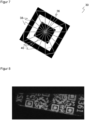
- This will be in Figure 6 illustrated, which shows an exemplary search pattern 30.
- parallel scan lines 32 are drawn through the image area to be examined, preferably horizontal scan lines, of which Figure 6 For the sake of clarity, only two are shown. Edge transitions 34 between light and dark code areas or, conversely, between dark and light code areas are determined along the scan lines 32.
- a step S12 the distances between the edge transitions of a scan line are checked.
- six consecutive edge transitions 34 must have mutual distances in the ratio 1:1:3:1:1. This is because the search pattern 30 consists of a center with 3x3 code modules, which are surrounded by two alternating rectangular rings the width of one code module each. This results in the mentioned ratio 1:1:3:1:1 any direction of the scan line 32 through the search pattern. If six edge transitions 34 are found along a scan line 32, taking into account a tolerance at intervals of 1:1:3:1:1, a search pattern 30 is assumed here.
- the associated candidate position is preferably the center of the edge transitions, calculated for example as the common center of gravity of all edge transitions or only the outermost of the six edge transitions considered.
- candidate positions of successive scan lines 32 are combined to form a candidate position 36, since this is not a new search pattern, but the same search pattern 30, which is hit several times by the successive scan lines 32.
- there are various calculation methods for example as the center of gravity of all edge transitions of the affected scan lines 32, only the outermost edge transitions per scan line 32 and / or only the outermost scan lines 32, or by determining a common center point from the several candidate positions per scan line 32.
- Figure 4 shows an exemplary flowchart for precisely locating the search pattern in an environment of the candidate position with possible substeps of step S20 of Figure 2 .
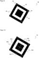
- a step S21 which is in Figure 7 Illustrated search pattern 30, starting from the candidate position 36, star-shaped rays 38 are formed, here for example sixteen of these rays 38 in a uniform angular grid with a mutual angular distance of 22.5 °.
- the three edge transitions closest to the origin in the candidate position 36 are determined on each of the beams 38.
- the candidate position 36 may differ from Figure 7 lie somewhat decentrally in the 3x3 center of search pattern 30, depending on the specific result of steps S10-S13.
- a step S22 the respective innermost, middle and outermost of the three edge transitions found per beam 38 are connected to one another. This creates three rings 40. If no three edge transitions could be found for a beam 38 in step S21, the corresponding point in the ring 40 is omitted. In case the candidate position is 36 as in Figure 7 lies in a search pattern 30, these rings 40 largely correspond to the light-dark transitions of the search pattern 30. This does not apply to some ring sections because of the simple creation of the rings 40 using connecting lines; this will be discussed immediately in step S23.
- Figure 8 For example, an image with several search patterns to which step S22 was applied.
- the existing search patterns are quite well captured by the rings.
- At the top right there is an example where points had to be skipped because no three edge transitions were found in some rays.
- there are some false positive candidate positions where the connecting lines can hardly be described as a ring and rather form a jumbled mess. This is because at these candidate positions the three edge transitions are formed by some structures, but not a search pattern, and are sometimes quite far away.
- the false positive candidate positions are filtered out in later steps. In principle they would be if the deviation is as significant as in some cases Figure 8 , can also be seen in the completely implausible distances between the edge transitions along the affected rays 38.
- a step S23 the ring sections of the rings 40 are confirmed.
- Figure 9 illustrates this for the outermost ring 40.
- To confirm a ring section it is checked whether the corresponding line runs on a light-dark edge. This hits home Figure 9 for the thus confirmed ring sections 42, the unconfirmed ring sections 44, however, run within a dark area and therefore on no light-dark edge.
- One way to find the confirmed ring sections 42 is to use a Sobel filter, which determines the respective direction of a light-dark transition.
- a confirmed ring section 42 must lie on the points identified by the Sobel filter, whereby individual outlier points can be tolerated.
- the ring sections 42, 44 are classified into two mutually orthogonal groups according to their direction of extension.
- the confirmed ring sections 42 are preferably used.
- Figure 9 It can be seen that the confirmed ring sections 42 run very clearly either horizontally or vertically to the search pattern 30, while the orientation of the unconfirmed ring sections 44 deviates.
- a respective main axis can be determined from the orientations of the assigned ring sections 42, 44, for example as the average orientation within the group.
- Figure 10 illustrates the two main axes 46a-b of the search pattern 30 found in this way.
- a ring section 42a-d is found in each of the four main directions on both sides of the main axes 46a-b, i.e. to the right, left, top and bottom according to the now known orientation of the search pattern 30.
- the frame can be refined by evaluating the surroundings of the straight lines, in particular additional scan lines orthogonal to the straight lines, and brought into even better agreement with the search pattern 30.
- a ring section 42a-d is reconstructed if no ring section 42a-d could be found in one of the main directions, or at least no ring section 42a-d of the outer ring.
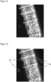
- Figure 11 shows an example image of a search pattern in which a ring section is missing at the top due to partial obscuration or another image error.
- the frame 48 is therefore reconstructed at the upper edge 48a.
- the well-recognized remaining edges of the frame 48 and/or ring sections of inner rings can be used.
- the known size ratios of a search pattern are also included in the reconstruction or extrapolation.
- edge 48a to be reconstructed should be approximately as far away from the candidate position 36 as the opposite lower edge.
- a ring section is also recognized towards the top, namely the inner and/or middle ring. Due to the structure of a search pattern, it is known what ratio the distance between the inner ring and the outer ring to be reconstructed is, namely following the distance ratios 1:1:3:1:1. Thanks to step S26, the position of a search pattern 30 is still recognized even in critical cases. There is an increased risk that more false positive search patterns will be recognized, which will be compensated for by the final verification now explained.
- Figure 5 shows an exemplary flowchart for verifying a search pattern with possible substeps of step S30 Figure 2 .
- Figure 12 illustrates verification based on an image of a search pattern 30.
- a step S31 seven mutually parallel half lines 50 are drawn for each main direction, i.e. to the right, left, up and down with respect to the known orientation with main axes 46a-b.
- the Half lines 50 run from one of the main axes 46a-b orthogonally over one half of the search pattern 30. With four such groups of seven half lines 50 each, there are a total of 28 half lines, which cover half the search pattern 30 four times in a mutual 90 ° rotation to each other.
- the half lines 50 can be spaced apart so that they each run through their own row of modules. This is achieved, for example, by evenly dividing the width or height of the search pattern 30, with deviations being harmless as long as each half line 50 continues to run through its own row of modules.
- the number seven of the half lines 50 is chosen to match the 7x7 code modules of the search pattern 30.
- a step S32 the edge transitions per half line 50 are determined. All you have to do is search over a length of the half line 50 that corresponds to half the size of the frame 48, possibly with a certain buffer. Edge transitions outside the frame 48 can no longer be traced back to a valid search pattern 30.
- a step S33 the number of edge transitions found per half line 50 is compared with the number that is expected in a search pattern 30, namely for the seven half lines 50 in this order 1, 2, 3, 3, 3, 2, 1 edge transitions.
- This required number is in Figure 12 noted at the end of the respective half line 50. It is also immediately clear from the illustration why this number is to be expected.
- the outer half lines 50 run completely within the dark outer rectangular ring of the search pattern, so that only a single edge transition should be found at the edge of the search pattern. In principle, it is conceivable to tolerate a deviation in the number of edge transitions on a half-line 50, but this greatly blurs the significance of the verification.
- an additional condition can be checked, namely whether the distances or positions of the edge transitions on the respective half-line 50 are plausible.
- the one expected edge transition of the outer half lines 50 is approximately at a distance of half the size of the search pattern 30 or the frame 48, whereby this distance can also be expressed as 31 ⁇ 2 module sizes. The same expectation applies to the respective furthest edge transition of the other half lines 50.
- the other half lines 50 have additional inner edge transitions that are expected at a distance of 11 ⁇ 2 or 21 ⁇ 2 module sizes. Tolerances are preferably to be provided for step S34, namely with regard to the expected distances and/or a quota of half lines 50 that must fulfill the condition of step S34.
- Figure 13 shows an example image with several search patterns that were found and verified by the method according to the invention.
- Figure 14 illustrates the associated verification with the half lines just explained. Dark half lines confirmed the search pattern, light half lines did not. At the points marked with reference number 52, the verification rightly failed at several candidate positions; only the correct search patterns were confirmed by the verification.
- a final test can be used to check whether three search patterns were found in an isosceles right-angled triangle.
- search patterns that do not meet this condition are immediately discarded, or, for example, an image area with only one or two search patterns or a different arrangement of the search patterns is given only secondary importance or less decoder time in the decoder.
- the inventive finding of Search patterns can also be used in the same way for an Aztec code, although three search patterns in the triangle are of course not expected, since an Aztec code only has a single search pattern in the center.
- the invention can also be used for other search patterns; conditions specific to QR codes or Aztec codes, such as the ratio 1:1:3:1:1, can then be adapted accordingly.
- more candidate positions can be initially accepted in order to increase the sensitivity of the localization of codes.
- search patterns that are difficult to recognize are also captured, such as partially obscured search patterns or those with poor contrast.
- the position of the search pattern found in each case, for example as a frame 48 is improved compared to a bounding box or other prior art methods. Because of the final verification, the higher number of candidate positions in no way leads to more false positive results.
- the search patterns recognized at the end of the process are even more reliable than in the prior art, meaning a high level of selectivity is also achieved. A reconstruction or extrapolation of search patterns is even permitted before verification.
Landscapes
- Engineering & Computer Science (AREA)
- Physics & Mathematics (AREA)
- Computer Vision & Pattern Recognition (AREA)
- Theoretical Computer Science (AREA)
- General Physics & Mathematics (AREA)
- Electromagnetism (AREA)
- General Health & Medical Sciences (AREA)
- Artificial Intelligence (AREA)
- Toxicology (AREA)
- Health & Medical Sciences (AREA)
- Multimedia (AREA)
- Quality & Reliability (AREA)
- Image Analysis (AREA)
Priority Applications (5)
| Application Number | Priority Date | Filing Date | Title |
|---|---|---|---|
| EP22193715.4A EP4332832B1 (fr) | 2022-09-02 | 2022-09-02 | Localisation d'un code optique |
| US18/226,889 US12260292B2 (en) | 2022-09-02 | 2023-07-27 | Localize an optical code |
| JP2023122278A JP7571217B2 (ja) | 2022-09-02 | 2023-07-27 | 光学コードの位置の特定 |
| KR1020230099443A KR20240032626A (ko) | 2022-09-02 | 2023-07-31 | 광학 코드의 위치 탐색 |
| CN202311112839.XA CN117648939A (zh) | 2022-09-02 | 2023-08-31 | 光学代码的定位 |
Applications Claiming Priority (1)
| Application Number | Priority Date | Filing Date | Title |
|---|---|---|---|
| EP22193715.4A EP4332832B1 (fr) | 2022-09-02 | 2022-09-02 | Localisation d'un code optique |
Publications (3)
| Publication Number | Publication Date |
|---|---|
| EP4332832A1 true EP4332832A1 (fr) | 2024-03-06 |
| EP4332832C0 EP4332832C0 (fr) | 2024-06-26 |
| EP4332832B1 EP4332832B1 (fr) | 2024-06-26 |
Family
ID=83191964
Family Applications (1)
| Application Number | Title | Priority Date | Filing Date |
|---|---|---|---|
| EP22193715.4A Active EP4332832B1 (fr) | 2022-09-02 | 2022-09-02 | Localisation d'un code optique |
Country Status (5)
| Country | Link |
|---|---|
| US (1) | US12260292B2 (fr) |
| EP (1) | EP4332832B1 (fr) |
| JP (1) | JP7571217B2 (fr) |
| KR (1) | KR20240032626A (fr) |
| CN (1) | CN117648939A (fr) |
Families Citing this family (1)
| Publication number | Priority date | Publication date | Assignee | Title |
|---|---|---|---|---|
| CN120764573B (zh) * | 2025-08-28 | 2025-11-07 | 琴海科技股份有限公司 | 一种二维码及其解码方法、系统与存储介质 |
Citations (5)
| Publication number | Priority date | Publication date | Assignee | Title |
|---|---|---|---|---|
| EP1383074A1 (fr) * | 2002-07-18 | 2004-01-21 | Sharp Kabushiki Kaisha | Appareil, procédé et programme-support de lecture d'un code bidimensionnel, terminal et caméra digitale |
| US20060050961A1 (en) * | 2004-08-13 | 2006-03-09 | Mohanaraj Thiyagarajah | Method and system for locating and verifying a finder pattern in a two-dimensional machine-readable symbol |
| US7546950B2 (en) | 2006-03-28 | 2009-06-16 | Seiko Epson Corporation | Method and apparatus for locating and decoding a two-dimensional machine-readable symbol |
| US9355293B2 (en) | 2008-12-22 | 2016-05-31 | Canon Kabushiki Kaisha | Code detection and decoding system |
| US9501681B1 (en) * | 2015-07-14 | 2016-11-22 | A9.Com, Inc. | Decoding visual codes |
Family Cites Families (7)
| Publication number | Priority date | Publication date | Assignee | Title |
|---|---|---|---|---|
| US5786583A (en) * | 1996-02-16 | 1998-07-28 | Intermec Corporation | Method and apparatus for locating and decoding machine-readable symbols |
| JP3834929B2 (ja) * | 1997-05-09 | 2006-10-18 | 株式会社デンソー | 光学的情報読取装置、情報処理装置、文書および記録媒体 |
| KR100828539B1 (ko) * | 2005-09-20 | 2008-05-13 | 후지제롯쿠스 가부시끼가이샤 | 이차원 코드의 검출 방법, 검출 장치, 및 검출 프로그램을기억한 기억 매체 |
| JP2007094584A (ja) * | 2005-09-27 | 2007-04-12 | Fuji Xerox Co Ltd | 二次元コードの検出方法、検出装置、及び検出プログラム |
| EP2093697B1 (fr) * | 2008-02-25 | 2017-08-23 | Telefonaktiebolaget LM Ericsson (publ) | Procédé et agencement pour récupérer des informations contenues dans un code-barres |
| JP4970385B2 (ja) * | 2008-08-12 | 2012-07-04 | 日本電信電話株式会社 | 2次元コード読取装置とそのプログラム |
| EP2921997B1 (fr) * | 2012-11-13 | 2021-01-06 | Kyodo Printing Co., Ltd. | Code à deux dimensions |
-
2022
- 2022-09-02 EP EP22193715.4A patent/EP4332832B1/fr active Active
-
2023
- 2023-07-27 JP JP2023122278A patent/JP7571217B2/ja active Active
- 2023-07-27 US US18/226,889 patent/US12260292B2/en active Active
- 2023-07-31 KR KR1020230099443A patent/KR20240032626A/ko not_active Ceased
- 2023-08-31 CN CN202311112839.XA patent/CN117648939A/zh active Pending
Patent Citations (6)
| Publication number | Priority date | Publication date | Assignee | Title |
|---|---|---|---|---|
| EP1383074A1 (fr) * | 2002-07-18 | 2004-01-21 | Sharp Kabushiki Kaisha | Appareil, procédé et programme-support de lecture d'un code bidimensionnel, terminal et caméra digitale |
| US20040020989A1 (en) | 2002-07-18 | 2004-02-05 | Takeharu Muramatsu | Two-dimensional code reading apparatus, two-dimensional code reading process, two-dimensional code reading program and recording medium for said program, portable terminal and digital camera |
| US20060050961A1 (en) * | 2004-08-13 | 2006-03-09 | Mohanaraj Thiyagarajah | Method and system for locating and verifying a finder pattern in a two-dimensional machine-readable symbol |
| US7546950B2 (en) | 2006-03-28 | 2009-06-16 | Seiko Epson Corporation | Method and apparatus for locating and decoding a two-dimensional machine-readable symbol |
| US9355293B2 (en) | 2008-12-22 | 2016-05-31 | Canon Kabushiki Kaisha | Code detection and decoding system |
| US9501681B1 (en) * | 2015-07-14 | 2016-11-22 | A9.Com, Inc. | Decoding visual codes |
Also Published As
| Publication number | Publication date |
|---|---|
| EP4332832C0 (fr) | 2024-06-26 |
| US12260292B2 (en) | 2025-03-25 |
| KR20240032626A (ko) | 2024-03-12 |
| EP4332832B1 (fr) | 2024-06-26 |
| JP7571217B2 (ja) | 2024-10-22 |
| JP2024035801A (ja) | 2024-03-14 |
| US20240078398A1 (en) | 2024-03-07 |
| CN117648939A (zh) | 2024-03-05 |
Similar Documents
| Publication | Publication Date | Title |
|---|---|---|
| EP3454298B1 (fr) | Système de caméra et procédé de détermination d'un flux d'objets | |
| EP3428834B1 (fr) | Lecteur de code optoélectronique et procédé de lecture de code optique | |
| DE69131216T2 (de) | Lagebestimmung von Strichkodierungen | |
| EP2417561B1 (fr) | Code a deux dimensions et procede | |
| DE69728482T2 (de) | Zweidimensionaler Codeleser | |
| EP2693364B1 (fr) | Système de caméra et procédé de détermination d'un flux d'objets | |
| DE69504069T2 (de) | Verfahren und gerät zu dekodierung von zweidimensionalen zeichen im raumbereich | |
| EP2555160B1 (fr) | Production d'une image présegmentée en domaines intéressants et inintéressants | |
| DE69324095T2 (de) | Verfahren und Vorrichtung zum Dedektieren von strichkodierten Symbolen mit Unterpixel-Interpolation | |
| EP3663963B1 (fr) | Lecture de codes optiques | |
| DE69629930T2 (de) | Verfahren zum Festlegen eines auf einem Objekt angebrachten optischen Codes | |
| EP3327611B1 (fr) | Dispositif de détection et procédé de détection d'un objet dotés d'une multitude de capteurs optoélectroniques | |
| DE102013112040B4 (de) | System und Verfahren zum Auffinden von sattelpunktartigen Strukturen in einem Bild und Bestimmen von Informationen daraus | |
| DE112022005421T5 (de) | Verfahren zur identifizierung einer zeichenorientierung und zur dekodierung von zeichen für maschinelle bildverarbeitungssysteme | |
| EP4290403B1 (fr) | Lecture d'un code optique unidimensionnel | |
| DE102020120887B4 (de) | Verfahren zum erfassen einer einhängeposition eines auflagestegs und flachbettwerkzeugmaschine | |
| EP4332832B1 (fr) | Localisation d'un code optique | |
| EP4312150B1 (fr) | Lecture d'un code optique | |
| DE69322923T2 (de) | Gerät zum Überprüfen eines Containerkodes | |
| DE2749222A1 (de) | Verfahren und vorrichtung zum automatischen erkennen oder lesen von zeichen | |
| EP4167123B1 (fr) | Lecteur de code basé sur une caméra et procédé de lecture de code optique | |
| EP3534291A1 (fr) | Dispositif de lecture de code optoélectronique et procédé de lecture de codes | |
| EP4287066B1 (fr) | Détermination de la taille de module d'un code optique | |
| EP4607404A1 (fr) | Lecture d'un code optique | |
| EP3142068B1 (fr) | Procede de detection tridimensionnelle d'objets |
Legal Events
| Date | Code | Title | Description |
|---|---|---|---|
| PUAI | Public reference made under article 153(3) epc to a published international application that has entered the european phase |
Free format text: ORIGINAL CODE: 0009012 |
|
| STAA | Information on the status of an ep patent application or granted ep patent |
Free format text: STATUS: REQUEST FOR EXAMINATION WAS MADE |
|
| 17P | Request for examination filed |
Effective date: 20230222 |
|
| AK | Designated contracting states |
Kind code of ref document: A1 Designated state(s): AL AT BE BG CH CY CZ DE DK EE ES FI FR GB GR HR HU IE IS IT LI LT LU LV MC MK MT NL NO PL PT RO RS SE SI SK SM TR |
|
| GRAP | Despatch of communication of intention to grant a patent |
Free format text: ORIGINAL CODE: EPIDOSNIGR1 |
|
| STAA | Information on the status of an ep patent application or granted ep patent |
Free format text: STATUS: GRANT OF PATENT IS INTENDED |
|
| INTG | Intention to grant announced |
Effective date: 20240405 |
|
| GRAS | Grant fee paid |
Free format text: ORIGINAL CODE: EPIDOSNIGR3 |
|
| GRAA | (expected) grant |
Free format text: ORIGINAL CODE: 0009210 |
|
| STAA | Information on the status of an ep patent application or granted ep patent |
Free format text: STATUS: THE PATENT HAS BEEN GRANTED |
|
| AK | Designated contracting states |
Kind code of ref document: B1 Designated state(s): AL AT BE BG CH CY CZ DE DK EE ES FI FR GB GR HR HU IE IS IT LI LT LU LV MC MK MT NL NO PL PT RO RS SE SI SK SM TR |
|
| REG | Reference to a national code |
Ref country code: GB Ref legal event code: FG4D Free format text: NOT ENGLISH |
|
| REG | Reference to a national code |
Ref country code: CH Ref legal event code: EP |
|
| REG | Reference to a national code |
Ref country code: DE Ref legal event code: R096 Ref document number: 502022001120 Country of ref document: DE |
|
| U01 | Request for unitary effect filed |
Effective date: 20240627 |
|
| U07 | Unitary effect registered |
Designated state(s): AT BE BG DE DK EE FI FR IT LT LU LV MT NL PT SE SI Effective date: 20240708 |
|
| PG25 | Lapsed in a contracting state [announced via postgrant information from national office to epo] |
Ref country code: HR Free format text: LAPSE BECAUSE OF FAILURE TO SUBMIT A TRANSLATION OF THE DESCRIPTION OR TO PAY THE FEE WITHIN THE PRESCRIBED TIME-LIMIT Effective date: 20240626 |
|
| PG25 | Lapsed in a contracting state [announced via postgrant information from national office to epo] |
Ref country code: GR Free format text: LAPSE BECAUSE OF FAILURE TO SUBMIT A TRANSLATION OF THE DESCRIPTION OR TO PAY THE FEE WITHIN THE PRESCRIBED TIME-LIMIT Effective date: 20240927 |
|
| U20 | Renewal fee for the european patent with unitary effect paid |
Year of fee payment: 3 Effective date: 20240925 |
|
| PG25 | Lapsed in a contracting state [announced via postgrant information from national office to epo] |
Ref country code: NO Free format text: LAPSE BECAUSE OF FAILURE TO SUBMIT A TRANSLATION OF THE DESCRIPTION OR TO PAY THE FEE WITHIN THE PRESCRIBED TIME-LIMIT Effective date: 20240926 Ref country code: HR Free format text: LAPSE BECAUSE OF FAILURE TO SUBMIT A TRANSLATION OF THE DESCRIPTION OR TO PAY THE FEE WITHIN THE PRESCRIBED TIME-LIMIT Effective date: 20240626 Ref country code: GR Free format text: LAPSE BECAUSE OF FAILURE TO SUBMIT A TRANSLATION OF THE DESCRIPTION OR TO PAY THE FEE WITHIN THE PRESCRIBED TIME-LIMIT Effective date: 20240927 Ref country code: RS Free format text: LAPSE BECAUSE OF FAILURE TO SUBMIT A TRANSLATION OF THE DESCRIPTION OR TO PAY THE FEE WITHIN THE PRESCRIBED TIME-LIMIT Effective date: 20240926 |
|
| PG25 | Lapsed in a contracting state [announced via postgrant information from national office to epo] |
Ref country code: PL Free format text: LAPSE BECAUSE OF FAILURE TO SUBMIT A TRANSLATION OF THE DESCRIPTION OR TO PAY THE FEE WITHIN THE PRESCRIBED TIME-LIMIT Effective date: 20240626 |
|
| PG25 | Lapsed in a contracting state [announced via postgrant information from national office to epo] |
Ref country code: IS Free format text: LAPSE BECAUSE OF FAILURE TO SUBMIT A TRANSLATION OF THE DESCRIPTION OR TO PAY THE FEE WITHIN THE PRESCRIBED TIME-LIMIT Effective date: 20241026 |
|
| PG25 | Lapsed in a contracting state [announced via postgrant information from national office to epo] |
Ref country code: SK Free format text: LAPSE BECAUSE OF FAILURE TO SUBMIT A TRANSLATION OF THE DESCRIPTION OR TO PAY THE FEE WITHIN THE PRESCRIBED TIME-LIMIT Effective date: 20240626 Ref country code: RO Free format text: LAPSE BECAUSE OF FAILURE TO SUBMIT A TRANSLATION OF THE DESCRIPTION OR TO PAY THE FEE WITHIN THE PRESCRIBED TIME-LIMIT Effective date: 20240626 |
|
| PG25 | Lapsed in a contracting state [announced via postgrant information from national office to epo] |
Ref country code: SM Free format text: LAPSE BECAUSE OF FAILURE TO SUBMIT A TRANSLATION OF THE DESCRIPTION OR TO PAY THE FEE WITHIN THE PRESCRIBED TIME-LIMIT Effective date: 20240626 Ref country code: ES Free format text: LAPSE BECAUSE OF FAILURE TO SUBMIT A TRANSLATION OF THE DESCRIPTION OR TO PAY THE FEE WITHIN THE PRESCRIBED TIME-LIMIT Effective date: 20240626 |
|
| PG25 | Lapsed in a contracting state [announced via postgrant information from national office to epo] |
Ref country code: SM Free format text: LAPSE BECAUSE OF FAILURE TO SUBMIT A TRANSLATION OF THE DESCRIPTION OR TO PAY THE FEE WITHIN THE PRESCRIBED TIME-LIMIT Effective date: 20240626 Ref country code: SK Free format text: LAPSE BECAUSE OF FAILURE TO SUBMIT A TRANSLATION OF THE DESCRIPTION OR TO PAY THE FEE WITHIN THE PRESCRIBED TIME-LIMIT Effective date: 20240626 Ref country code: RO Free format text: LAPSE BECAUSE OF FAILURE TO SUBMIT A TRANSLATION OF THE DESCRIPTION OR TO PAY THE FEE WITHIN THE PRESCRIBED TIME-LIMIT Effective date: 20240626 Ref country code: PL Free format text: LAPSE BECAUSE OF FAILURE TO SUBMIT A TRANSLATION OF THE DESCRIPTION OR TO PAY THE FEE WITHIN THE PRESCRIBED TIME-LIMIT Effective date: 20240626 Ref country code: IS Free format text: LAPSE BECAUSE OF FAILURE TO SUBMIT A TRANSLATION OF THE DESCRIPTION OR TO PAY THE FEE WITHIN THE PRESCRIBED TIME-LIMIT Effective date: 20241026 Ref country code: ES Free format text: LAPSE BECAUSE OF FAILURE TO SUBMIT A TRANSLATION OF THE DESCRIPTION OR TO PAY THE FEE WITHIN THE PRESCRIBED TIME-LIMIT Effective date: 20240626 |
|
| PG25 | Lapsed in a contracting state [announced via postgrant information from national office to epo] |
Ref country code: MC Free format text: LAPSE BECAUSE OF FAILURE TO SUBMIT A TRANSLATION OF THE DESCRIPTION OR TO PAY THE FEE WITHIN THE PRESCRIBED TIME-LIMIT Effective date: 20240626 |
|
| PLBE | No opposition filed within time limit |
Free format text: ORIGINAL CODE: 0009261 |
|
| STAA | Information on the status of an ep patent application or granted ep patent |
Free format text: STATUS: NO OPPOSITION FILED WITHIN TIME LIMIT |
|
| 26N | No opposition filed |
Effective date: 20250327 |
|
| PG25 | Lapsed in a contracting state [announced via postgrant information from national office to epo] |
Ref country code: IE Free format text: LAPSE BECAUSE OF NON-PAYMENT OF DUE FEES Effective date: 20240902 |
|
| REG | Reference to a national code |
Ref country code: CH Ref legal event code: U11 Free format text: ST27 STATUS EVENT CODE: U-0-0-U10-U11 (AS PROVIDED BY THE NATIONAL OFFICE) Effective date: 20251001 |
|
| PGFP | Annual fee paid to national office [announced via postgrant information from national office to epo] |
Ref country code: CZ Payment date: 20250821 Year of fee payment: 4 |
|
| U20 | Renewal fee for the european patent with unitary effect paid |
Year of fee payment: 4 Effective date: 20250923 |
|
| PGFP | Annual fee paid to national office [announced via postgrant information from national office to epo] |
Ref country code: CH Payment date: 20251001 Year of fee payment: 4 |
|
| PG25 | Lapsed in a contracting state [announced via postgrant information from national office to epo] |
Ref country code: CY Free format text: LAPSE BECAUSE OF FAILURE TO SUBMIT A TRANSLATION OF THE DESCRIPTION OR TO PAY THE FEE WITHIN THE PRESCRIBED TIME-LIMIT; INVALID AB INITIO Effective date: 20220902 |
|
| PG25 | Lapsed in a contracting state [announced via postgrant information from national office to epo] |
Ref country code: HU Free format text: LAPSE BECAUSE OF FAILURE TO SUBMIT A TRANSLATION OF THE DESCRIPTION OR TO PAY THE FEE WITHIN THE PRESCRIBED TIME-LIMIT; INVALID AB INITIO Effective date: 20220902 |