EP4333092A1 - Matériau d'électrode positive pour dispositif électrique, et électrode positive pour dispositif électrique et dispositif électrique l'utilisant - Google Patents
Matériau d'électrode positive pour dispositif électrique, et électrode positive pour dispositif électrique et dispositif électrique l'utilisant Download PDFInfo
- Publication number
- EP4333092A1 EP4333092A1 EP21938144.9A EP21938144A EP4333092A1 EP 4333092 A1 EP4333092 A1 EP 4333092A1 EP 21938144 A EP21938144 A EP 21938144A EP 4333092 A1 EP4333092 A1 EP 4333092A1
- Authority
- EP
- European Patent Office
- Prior art keywords
- positive electrode
- solid electrolyte
- electric device
- sulfur
- active material
- Prior art date
- Legal status (The legal status is an assumption and is not a legal conclusion. Google has not performed a legal analysis and makes no representation as to the accuracy of the status listed.)
- Withdrawn
Links
Images


Classifications
-
- H—ELECTRICITY
- H01—ELECTRIC ELEMENTS
- H01M—PROCESSES OR MEANS, e.g. BATTERIES, FOR THE DIRECT CONVERSION OF CHEMICAL ENERGY INTO ELECTRICAL ENERGY
- H01M4/00—Electrodes
- H01M4/02—Electrodes composed of, or comprising, active material
- H01M4/13—Electrodes for accumulators with non-aqueous electrolyte, e.g. for lithium-accumulators; Processes of manufacture thereof
- H01M4/136—Electrodes based on inorganic compounds other than oxides or hydroxides, e.g. sulfides, selenides, tellurides, halogenides or LiCoFy
-
- H—ELECTRICITY
- H01—ELECTRIC ELEMENTS
- H01M—PROCESSES OR MEANS, e.g. BATTERIES, FOR THE DIRECT CONVERSION OF CHEMICAL ENERGY INTO ELECTRICAL ENERGY
- H01M4/00—Electrodes
- H01M4/02—Electrodes composed of, or comprising, active material
- H01M4/36—Selection of substances as active materials, active masses, active liquids
- H01M4/58—Selection of substances as active materials, active masses, active liquids of inorganic compounds other than oxides or hydroxides, e.g. sulfides, selenides, tellurides, halogenides or LiCoFy; of polyanionic structures, e.g. phosphates, silicates or borates
- H01M4/581—Chalcogenides or intercalation compounds thereof
- H01M4/5815—Sulfides
-
- H—ELECTRICITY
- H01—ELECTRIC ELEMENTS
- H01M—PROCESSES OR MEANS, e.g. BATTERIES, FOR THE DIRECT CONVERSION OF CHEMICAL ENERGY INTO ELECTRICAL ENERGY
- H01M10/00—Secondary cells; Manufacture thereof
- H01M10/05—Accumulators with non-aqueous electrolyte
- H01M10/052—Li-accumulators
-
- H—ELECTRICITY
- H01—ELECTRIC ELEMENTS
- H01M—PROCESSES OR MEANS, e.g. BATTERIES, FOR THE DIRECT CONVERSION OF CHEMICAL ENERGY INTO ELECTRICAL ENERGY
- H01M10/00—Secondary cells; Manufacture thereof
- H01M10/05—Accumulators with non-aqueous electrolyte
- H01M10/052—Li-accumulators
- H01M10/0525—Rocking-chair batteries, i.e. batteries with lithium insertion or intercalation in both electrodes; Lithium-ion batteries
-
- H—ELECTRICITY
- H01—ELECTRIC ELEMENTS
- H01M—PROCESSES OR MEANS, e.g. BATTERIES, FOR THE DIRECT CONVERSION OF CHEMICAL ENERGY INTO ELECTRICAL ENERGY
- H01M10/00—Secondary cells; Manufacture thereof
- H01M10/05—Accumulators with non-aqueous electrolyte
- H01M10/056—Accumulators with non-aqueous electrolyte characterised by the materials used as electrolytes, e.g. mixed inorganic/organic electrolytes
- H01M10/0561—Accumulators with non-aqueous electrolyte characterised by the materials used as electrolytes, e.g. mixed inorganic/organic electrolytes the electrolyte being constituted of inorganic materials only
- H01M10/0562—Solid materials
-
- H—ELECTRICITY
- H01—ELECTRIC ELEMENTS
- H01M—PROCESSES OR MEANS, e.g. BATTERIES, FOR THE DIRECT CONVERSION OF CHEMICAL ENERGY INTO ELECTRICAL ENERGY
- H01M4/00—Electrodes
- H01M4/02—Electrodes composed of, or comprising, active material
- H01M4/04—Processes of manufacture in general
- H01M4/0471—Processes of manufacture in general involving thermal treatment, e.g. firing, sintering, backing particulate active material, thermal decomposition, pyrolysis
-
- H—ELECTRICITY
- H01—ELECTRIC ELEMENTS
- H01M—PROCESSES OR MEANS, e.g. BATTERIES, FOR THE DIRECT CONVERSION OF CHEMICAL ENERGY INTO ELECTRICAL ENERGY
- H01M4/00—Electrodes
- H01M4/02—Electrodes composed of, or comprising, active material
- H01M4/13—Electrodes for accumulators with non-aqueous electrolyte, e.g. for lithium-accumulators; Processes of manufacture thereof
- H01M4/139—Processes of manufacture
- H01M4/1397—Processes of manufacture of electrodes based on inorganic compounds other than oxides or hydroxides, e.g. sulfides, selenides, tellurides, halogenides or LiCoFy
-
- H—ELECTRICITY
- H01—ELECTRIC ELEMENTS
- H01M—PROCESSES OR MEANS, e.g. BATTERIES, FOR THE DIRECT CONVERSION OF CHEMICAL ENERGY INTO ELECTRICAL ENERGY
- H01M4/00—Electrodes
- H01M4/02—Electrodes composed of, or comprising, active material
- H01M4/36—Selection of substances as active materials, active masses, active liquids
- H01M4/362—Composites
- H01M4/364—Composites as mixtures
-
- H—ELECTRICITY
- H01—ELECTRIC ELEMENTS
- H01M—PROCESSES OR MEANS, e.g. BATTERIES, FOR THE DIRECT CONVERSION OF CHEMICAL ENERGY INTO ELECTRICAL ENERGY
- H01M4/00—Electrodes
- H01M4/02—Electrodes composed of, or comprising, active material
- H01M4/36—Selection of substances as active materials, active masses, active liquids
- H01M4/38—Selection of substances as active materials, active masses, active liquids of elements or alloys
-
- H—ELECTRICITY
- H01—ELECTRIC ELEMENTS
- H01M—PROCESSES OR MEANS, e.g. BATTERIES, FOR THE DIRECT CONVERSION OF CHEMICAL ENERGY INTO ELECTRICAL ENERGY
- H01M4/00—Electrodes
- H01M4/02—Electrodes composed of, or comprising, active material
- H01M4/62—Selection of inactive substances as ingredients for active masses, e.g. binders, fillers
- H01M4/624—Electric conductive fillers
- H01M4/625—Carbon or graphite
-
- H—ELECTRICITY
- H01—ELECTRIC ELEMENTS
- H01M—PROCESSES OR MEANS, e.g. BATTERIES, FOR THE DIRECT CONVERSION OF CHEMICAL ENERGY INTO ELECTRICAL ENERGY
- H01M4/00—Electrodes
- H01M4/02—Electrodes composed of, or comprising, active material
- H01M2004/021—Physical characteristics, e.g. porosity, surface area
-
- H—ELECTRICITY
- H01—ELECTRIC ELEMENTS
- H01M—PROCESSES OR MEANS, e.g. BATTERIES, FOR THE DIRECT CONVERSION OF CHEMICAL ENERGY INTO ELECTRICAL ENERGY
- H01M4/00—Electrodes
- H01M4/02—Electrodes composed of, or comprising, active material
- H01M2004/026—Electrodes composed of, or comprising, active material characterised by the polarity
- H01M2004/028—Positive electrodes
-
- H—ELECTRICITY
- H01—ELECTRIC ELEMENTS
- H01M—PROCESSES OR MEANS, e.g. BATTERIES, FOR THE DIRECT CONVERSION OF CHEMICAL ENERGY INTO ELECTRICAL ENERGY
- H01M2300/00—Electrolytes
- H01M2300/0017—Non-aqueous electrolytes
- H01M2300/0065—Solid electrolytes
- H01M2300/0068—Solid electrolytes inorganic
-
- Y—GENERAL TAGGING OF NEW TECHNOLOGICAL DEVELOPMENTS; GENERAL TAGGING OF CROSS-SECTIONAL TECHNOLOGIES SPANNING OVER SEVERAL SECTIONS OF THE IPC; TECHNICAL SUBJECTS COVERED BY FORMER USPC CROSS-REFERENCE ART COLLECTIONS [XRACs] AND DIGESTS
- Y02—TECHNOLOGIES OR APPLICATIONS FOR MITIGATION OR ADAPTATION AGAINST CLIMATE CHANGE
- Y02E—REDUCTION OF GREENHOUSE GAS [GHG] EMISSIONS, RELATED TO ENERGY GENERATION, TRANSMISSION OR DISTRIBUTION
- Y02E60/00—Enabling technologies; Technologies with a potential or indirect contribution to GHG emissions mitigation
- Y02E60/10—Energy storage using batteries
Definitions
- the present invention relates to a positive electrode material for an electric device, a positive electrode for an electric device and an electric device using the positive electrode material for an electric device.
- a known large-capacity negative electrode material to be used in an all-solid battery is metallic lithium, i.e., a negative electrode active material which supplies lithium ions to a positive electrode.
- metallic lithium i.e., a negative electrode active material which supplies lithium ions to a positive electrode.
- the metallic lithium reacts with the sulfide solid electrolyte, and thus the battery characteristics may be deteriorated.
- WO 2012/102037 proposes a technique in which a composite material containing a conductive agent and an alkali metal sulfide integrated with the surface of the conductive agent is used as a positive electrode material for an all-solid battery.
- a positive electrode material having such a configuration makes it possible to provide a positive electrode material as well as a lithium-ion battery which have a high theoretical capacity and can use a negative electrode active material which does not supply lithium ions to the positive electrode.
- an object of the present invention is to provide a means for enhancing capacity performance and charge-discharge rate capability of an electric device which uses a positive electrode active material containing sulfur.
- the present inventors have carried out a diligent study in order to solve the problem described above. As a result, it has been found that the problem described above can be solved by using a positive electrode material for an electric device showing a peak in a predetermined wave number region of a Raman spectrum among positive electrode materials for an electric device containing a sulfur-containing positive electrode active material and a sulfur-containing solid electrolyte, and the present invention has been completed.
- One aspect of the present invention is a positive electrode material for an electric device that contains a sulfur-containing positive electrode active material and a sulfur-containing solid electrolyte, and shows a peak in a range of 1400 to 1450 cm -1 in a Raman spectrum of microscopic Raman spectrometry using a laser with a wavelength of 532 nm.
- capacity characteristics and charge-discharge rate characteristics can be improved in an electric device using a sulfur-containing positive electrode active material.
- Fig. 1 is a perspective view illustrating an appearance of a flat laminate type all-solid lithium secondary battery as one embodiment of the present invention.
- Fig. 2 is a cross-sectional view taken along line 2-2 illustrated in Fig. 1 .
- the embodiment will be described by taking, as an example, a case where a secondary battery is a flat laminate type (non-bipolar type) lithium-ion secondary battery illustrated in Figs. 1 and 2 (hereinafter also simply referred to as "laminate type battery").
- a laminate type battery 10a has a rectangular flat shape, and a negative electrode current collecting plate 25 and a positive electrode current collecting plate 27 for extracting electric power are extended from both sides of the battery.
- a power generating element 21 is wrapped in a battery outer casing material (laminate film 29) of the laminate type battery 10a, and the periphery of the battery outer casing material is heat-sealed, and the power generating element 21 is hermetically sealed in a state where the negative electrode current collecting plate 25 and the positive electrode current collecting plate 27 are extended to the outside.
- the laminate type battery 10a of the present embodiment has a structure in which the flat and substantially rectangular power-generating element 21 in which a charge and discharge reaction actually proceeds is sealed inside the laminate film 29 as the battery outer casing material.
- the power-generating element 21 has a configuration in which a positive electrode, a solid electrolyte layer 17, and a negative electrode are laminated.
- the positive electrode has a structure in which a positive electrode active material layer 15 containing a positive electrode active material is disposed on both surfaces of a positive electrode current collector 11".
- the negative electrode has a structure in which a negative electrode active material layer 13 containing a negative electrode active material is disposed on both surfaces of a negative electrode current collector 11'.
- the positive electrode, solid electrolyte layer, and negative electrode that are adjacent constitute one single battery layer 19.
- the negative electrode current collector 11' and the positive electrode current collector 11" have a structure in which a negative electrode current collecting plate (tab) 25 and a positive electrode current collecting plate (tab) 27 which are electrically connected to the respective electrodes (the positive electrode and the negative electrode) are respectively attached to the negative electrode current collector 11' and the positive electrode current collector 11" and are led to an outside of the laminate film 29 so as to be sandwiched between ends of the laminate film 29 as the outer casing material.
- a negative electrode current collecting plate (tab) 25 and a positive electrode current collecting plate (tab) 27 which are electrically connected to the respective electrodes (the positive electrode and the negative electrode) are respectively attached to the negative electrode current collector 11' and the positive electrode current collector 11" and are led to an outside of the laminate film 29 so as to be sandwiched between ends of the laminate film 29 as the outer casing material.
- a current collector has a function of mediating transfer of electrons from electrode active material layers. Further, as long as a negative electrode active material layer and a positive electrode active material layer to be described later have conductivity by themselves and can have a current collecting function, a current collector as a member different from these electrode active material layers is not necessarily used.
- a negative electrode active material layer 13 contains a negative electrode active material.
- the type of the negative electrode active material is not particularly limited, and the examples thereof include a carbon material, a metal oxide, and a metal active material.
- a metal containing lithium may be used as the negative electrode active material.
- Such negative electrode active material is not particularly limited as long as the negative electrode active material is an active material containing lithium, and examples thereof include a lithium-containing alloy as well as metal lithium. Examples of the lithium-containing alloy include an alloy of Li and at least one of In, Al, Si, and Sn.
- the negative electrode active material preferably contains the metal lithium or the lithium-containing alloy, a silicon-based negative electrode active material, or a tin-based negative electrode active material, and particularly preferably contains the metal lithium or the lithium-containing alloy.
- a lithium secondary battery as the electric device may be a so-called lithium-precipitation type lithium secondary battery in which lithium metal as the negative electrode active material is precipitated on a negative electrode current collector in a charge process. Therefore, in such an embodiment, a thickness of the negative electrode active material layer increases with progress of the charging process, and the thickness of the negative electrode active material layer decreases with progress of a discharge process.
- the negative electrode active material layer may not be present at the time of complete discharge, but in some cases, the negative electrode active material layer containing a certain amount of the lithium metal may be disposed at the time of complete discharge.
- the content of the negative electrode active material in the negative electrode active material layer is not particularly limited, but for example, is preferably within a range of 40 to 99 mass%, and more preferably within a range of 50 to 90 mass%.
- the negative electrode active material layer further contains a solid electrolyte.
- the solid electrolyte include a sulfide solid electrolyte and an oxide solid electrolyte, and a sulfide solid electrolyte is preferred.
- Examples of the sulfide solid electrolyte include LiI-Li 2 S-SiS 2 , LiI-Li 2 S-P 2 O 5 , LiI-Li 3 PO 4 -P 2 S 5 , Li 2 S-P 2 S 5 , LiI-Li 3 PS 4 , LiI-LiBr-Li 3 PS 4 , Li 3 PS 4 , Li 2 S-P 2 S 5 -LiI, Li 2 S-P 2 S 5 -Li 2 O, Li 2 S-P 2 S 5 -Li 2 O-LiI, Li 2 S-SiS 2 , Li 2 S-SiS 2 -LiI, Li 2 S-SiS 2 -LiBr, Li 2 S-SiS 2 -LiCl, Li 2 S-SiS 2 -B 2 S 3 -LiI, Li 2 S-SiS 2 -P 2 S 5 -LiI, Li 2 S-B 2 S 3 , Li 2 S
- the sulfide solid electrolyte may have, for example, a Li 3 PS 4 skeleton, a Li 4 P 2 S 7 skeleton, or a Li 4 P 2 S 6 skeleton.
- Examples of the sulfide solid electrolyte having a Li 3 PS 4 skeleton include LiI-Li 3 PS 4 , LiI-LiBr-Li 3 PS 4 , and Li 3 PS 4 .
- Examples of the sulfide solid electrolyte having a Li 4 P 2 S 7 skeleton include a Li-P-S-based solid electrolyte called LPS (e.g., Li 7 P 3 S 11 ).
- the sulfide solid electrolyte for example, LGPS expressed by Li (4-x) Ge (1-x) P x S 4 (x satisfies 0 ⁇ x ⁇ 1) or the like may be used.
- the sulfide solid electrolyte contained in the active material layer is preferably a sulfide solid electrolyte containing a P element, and the sulfide solid electrolyte is more preferably a material containing Li 2 S-P 2 S 5 as a main component.
- the sulfide solid electrolyte may contain halogen (F, Cl, Br, I).
- the sulfide solid electrolyte contains Li 6 PS 5 X (where X is Cl, Br, or I, preferably Cl).
- Ion conductivity (e.g., Li ion conductivity) of the sulfide solid electrolyte at a normal temperature (25°C) is, for example, preferably 1 ⁇ 10 -5 S/cm or more, and more preferably 1 ⁇ 10 -4 S/cm or more.
- a value of the ion conductivity of the solid electrolyte can be measured by an AC impedance method.
- oxide solid electrolyte examples include a compound having a NASICON-type structure, and the like.
- Other examples of the oxide solid electrolyte include LiLaTiO (e.g., Li 0.34 La 0.51 TiO 3 ), LiPON (e.g., Li 2.9 PO 3.3 N 0.46 ), LiLaZrO (e.g., Li 7 La 3 Zr 2 O 12 ), and the like.
- the content of the solid electrolyte in the negative electrode active material layer is, for example, preferably within a range of 1 to 60 mass%, and more preferably within a range of 10 to 50 mass%.
- the negative electrode active material layer may further contain at least one of a conductive aid and a binder in addition to the negative electrode active material and the solid electrolyte described above.
- the thickness of the negative electrode active material layer varies depending on the configuration of the intended secondary battery, but is preferably, for example, within a range of 0.1 to 1000 ⁇ m.
- the solid electrolyte layer is interposed between the positive electrode active material layer and negative electrode active material layer described above and essentially contains a solid electrolyte.
- a specific form of the solid electrolyte contained in the solid electrolyte layer is not particularly limited, and examples and preferred forms of the solid electrolyte described in the section of the negative electrode active material layer are adopted in the same manner.
- the solid electrolyte layer may further contain a binder in addition to the predetermined solid electrolyte described above.
- the thickness of the solid electrolyte layer varies depending on the configuration of the intended lithium-ion secondary battery, but is preferably 600 um or less, more preferably 500 um or less, and still more preferably 400 um or less from the viewpoint that the volume energy density of the battery can be improved. Meanwhile, the lower limit of the thickness of the solid electrolyte layer is not particularly limited, but is preferably 1 um or more, more preferably 5 um or more, and still more preferably 10 um or more.
- a positive electrode active material layer contains a positive electrode material for an electric device according to one aspect of the present invention.
- the positive electrode material for an electric device essentially contains a sulfur-containing positive electrode active material and a sulfur-containing solid electrolyte, and preferably further contains a conductive material.
- the type of the sulfur-containing positive electrode active material is not particularly limited, but examples thereof include a particle or a thin film of an organic sulfur compound or an inorganic sulfur compound in addition to a sulfur simple substance (S) and lithium sulfide (Li 2 S), and any material may be used as long as the material can release lithium ions during charge and occlude the lithium ions during discharge by utilizing an oxidation-reduction reaction of the sulfur.
- S sulfur simple substance
- Li 2 S lithium sulfide
- the inorganic sulfur compound is preferable for being excellent in stability, and specific examples thereof include the sulfur simple substance (S), TiS 2 , TiS 2 , TiS 4 , NiS, NiS 2 , CuS, FeS 2 , Li 2 S, MoS 2 , MoS 3 , MnS, MnS 2 , CoS, CoS 2 , or the like.
- the S, an S-carbon composite, TiS 2 , TiS 3 , TiS 4 , FeS 2 , and MoS 2 are preferable, the sulfur simple substance (S) and the lithium sulfide (Li 2 S), TiS 2 , and FeS 2 are more preferable, and the sulfur simple substance (S) and the lithium sulfide (Li 2 S) are particularly preferable from a viewpoint of high capacity.
- the positive electrode material according to the present aspect may further contain a sulfur-free positive electrode active material, in addition to the positive electrode active material containing sulfur.
- a ratio of a content of the positive electrode active material containing sulfur to a total amount of 100 mass% of the positive electrode active material is preferably 50 mass% or more, more preferably 70 mass% or more, still more preferably 80 mass% or more, yet still more preferably 90 mass% or more, particularly preferably 95 mass% or more, and most preferably 100 mass .
- the positive electrode material according to the present aspect essentially contains a sulfur-containing solid electrolyte.
- a specific form of the sulfur-containing solid electrolyte contained in the positive electrode material according to the present aspect is not particularly limited, and the sulfur-containing solid electrolyte exemplified in the section of the negative electrode active material layer and a preferred form thereof can be similarly employed.
- the solid electrolyte contained in the positive electrode material according to the present aspect is preferably a sulfide solid electrolyte.
- the sulfur-containing solid electrolyte contained in a solid electrolyte layer contains an alkali metal atom.
- the alkali metal atom that can be contained in the sulfur-containing solid electrolyte include a lithium atom, a sodium atom, or a potassium atom, and among the atoms, the lithium atom is preferable from the viewpoint of excellent ionic conductivity.
- the solid electrolyte contained in the solid electrolyte layer contains an alkali metal atom (for example, lithium atom, sodium atom or potassium atom; preferably lithium atom) as well as a phosphorus atom and/or a boron atom.
- the sulfide solid electrolyte includes Li 6 PS 5 X (wherein X is Cl, Br or I, and preferably Cl). These solid electrolytes can also effectively contribute to expression of the effect of the present invention for having a high ionic conductivity.
- the positive electrode material according to the present aspect preferably further contains a conductive material.
- the specific form of the conductive material contained in the positive electrode material according to the present aspect is not particularly limited, and conventionally known materials can be appropriately adopted.
- the conductive material more preferably has pores.
- the conductive material having pores there is an advantage that the positive electrode active material and the solid electrolyte can be filled in inner portions of the pores, and a three-phase interface containing these three materials is formed and the positive electrode reaction is more likely to proceed.
- the conductive material having pores is preferably a carbon material from the viewpoint of excellent conductivity, ease of processing, and ease of designing a desired pore distribution.
- Examples of the carbon material having pores include carbon black, such as activated carbon, ketjen black (registered trademark) (highly conductive carbon black), (oil) furnace black, channel black, acetylene black, thermal black, and lamp black; and carbon particles (carbon carriers) made of coke, natural graphite, artificial graphite, and the like.
- the main component of the carbon material is preferably carbon.
- the phrase "the main component is carbon” means that carbon atoms are contained as a main component, and includes the concept of consisting only of carbon atoms and the concept of consisting substantially of carbon atoms.
- the phrase “consisting substantially of carbon atoms” means that the mixing of approximately 2 to 3 mass% or less of impurities may be allowable.
- the BET specific surface area of the conductive material having pores is preferably 200 m 2 /g or more, more preferably 500 m 2 /g or more, still more preferably 800 m 2 /g or more, particularly preferably 1200 m 2 /g or more, and most preferably 1500 m 2 /g or more.
- the pore volume of the conductive material is preferably 1.0 mL/g or more, more preferably 1.3 mL/g or more, and still more preferably 1.5 mL/g or more.
- the BET specific surface area and pore volume of the conductive material can be measured based on adsorption and desorption of nitrogen.
- the measurement based on adsorption and desorption of nitrogen at a temperature of -196°C is performed using BELSORP mini, manufactured by MicrotracBEL Corp., and analysis is conducted by a multipoint method.
- the BET specific surface area is determined from the adsorption isotherm in a relative pressure range of 0.01 ⁇ P/P 0 ⁇ 0.05.
- the pore volume is determined from the volume of the adsorbed N 2 at a relative pressure of 0.96.
- An average pore size of the conductive material is not particularly limited, but is preferably 50 nm or less, and particularly preferably 30 nm or less. When the average pore size is a value within these ranges, electrons can be sufficiently supplied to the active material present at a position away from the pore wall, among the positive electrode active materials containing sulfur placed in the pores. Note that the average pore size of the conductive material can be calculated by the measurement based on adsorption and desorption of nitrogen, in the same manner as above.
- An average particle diameter (primary particle diameter) in a case where the conductive material is in particle form is not particularly limited, but is preferably in a range of 0.05 to 50 um, more preferably in a range of 0.1 to 20 ⁇ m, and still more preferably in a range of 0.5 to 10 um.
- a particle diameter of the conductive material means a maximum distance L among distances between any two points on a contour line of the conductive material.
- an average particle diameter of the conductive material a value is adopted that is calculated as an average value of particle diameters of particles observed in several to several tens of fields of view by using an observation means such as a scanning electron microscope (SEM), a transmission electron microscope (TEM), or the like.
- the positive electrode material according to the present aspect contains a sulfur-containing positive electrode active material and a sulfur-containing solid electrolyte, but in a case where the positive electrode material further includes a conductive material having pores, it is preferable that at least a part of the solid electrolyte and at least a part of the positive electrode active material are disposed on inner surfaces of the pores of the conductive material described above to be in contact with each other.
- Fig. 3A is a schematic cross-sectional view of a positive electrode material 100' in the related art.
- Fig. 3B is a schematic cross-sectional view of a positive electrode material 100 according to one embodiment of the present invention.
- a carbon material (e.g., activated carbon) 110 which is a conductive material, has a large number of pores 110a.
- Sulfur 120 which is a positive electrode active material, is filled and placed in the pores 110a.
- the positive electrode active material (sulfur) 120 is also placed on the surface of the carbon material (activated carbon) 110.
- a solid electrolyte 130 is placed only on the surface of the carbon material (activated carbon) 110.
- a solid electrolyte 130 is present in a highly dispersed state in a positive electrode active material (sulfur) 120 disposed on the surface of the carbon material (an activated carbon) 110 and the inner surfaces of the pores of the carbon material (the activated carbon) 110.
- a continuous phase containing the positive electrode active material (sulfur) 120 is filled in the inner portions of pores 110a and is also present on the surface of the carbon material (the activated carbon) 110, and the solid electrolyte 130 is disposed as a dispersed phase in the continuous phase. Accordingly, at least a part of the solid electrolyte disposed on the surface of the conductive material (the activated carbon) and at least a part of the positive electrode active material (sulfur) similarly disposed on the surface of the conductive material (the activated carbon) are in contact with each other. With such configuration, it is possible to form particularly many reaction points (three-phase interfaces), and it is possible to effectively contribute to improvement in performance of the electric device.
- mapping of elements derived from each material is performed on an observed image of a cross section of the conductive material contained in the positive electrode material with the transmission electron microscope (TEM) by using energy dispersive X-ray spectroscopy (EDX), and an arrangement form of each material can be confirmed by using an element map obtained and a count number of the elements derived from each material with respect to the count number of all elements as an index.
- TEM transmission electron microscope
- EDX energy dispersive X-ray spectroscopy
- the sulfur-containing solid electrolyte essentially contains a phosphorus atom and there is no possibility that the phosphorus atom is derived from other materials
- the ratio of the count number of elements derived only from the solid electrolyte to the count number of all elements in EDX is 0.10 or more, it can be determined that the solid electrolyte is placed in the pores of the conductive material. Further, the ratio is preferably 0.15 or more, more preferably 0.20 or more, still more preferably 0.26 or more, and particularly preferably 0.35 or more. A large value of the ratio indicates that a large amount of the solid electrolyte is placed on the inner surface of the pores of the conductive material.
- a preferable upper limit of the ratio is not particularly limited, but the preferable upper limit is, for example, 0.50 or less, and more preferably 0.45 or less.
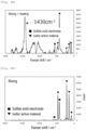
- the positive electrode material for an electric device is characterized in that a peak is shown in a range of 1400 to 1450 cm -1 in the Raman spectrum of the microscopic Raman spectrometry using the laser with the wavelength of 532 nm for the powder particles of the positive electrode material.
- Fig. 4A is a graph illustrating a Raman spectrum obtained by performing microscopic Raman spectrometry using a laser with the wavelength of 532 nm on the powder particles of the positive electrode material for an electric device prepared in Example 1 to be described later.
- the Raman spectrum of the positive electrode material for an electric device according to the present aspect first shows a peak considered to be derived from each of a sulfur active material and the sulfide solid electrolyte in a region of 600 cm -1 or less.
- the Raman spectrum of the positive electrode material for an electric device according to the present aspect is characterized in that a peak is also observed near 1430 cm -1 in addition to the peak described above.
- the electric device such as an all-solid-state lithium secondary battery or the like is configured by using a positive electrode material that contains a sulfur-containing positive electrode active material and a sulfur-containing solid electrolyte, and shows the peak in the range of 1400 to 1450 cm -1 in a Raman spectrum of the microscopic Raman spectroscopy using the laser with the wavelength of 532 nm, the capacity characteristics and the charge-discharge rate characteristics can be significantly improved. Although such mechanism is not completely clear, the mechanism below is presumed.
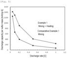
- the positive electrode material having the peak determined above according to the present aspect can be produced, for example, by mixing the sulfur-containing positive electrode active material and the sulfur-containing solid electrolyte to obtain a mixture, and then heating the mixture at a relatively high temperature (185°C in Example 1) as described later.
- a relatively high temperature 185°C in Example 1
- Comparative Example 1 in which such heating treatment is not performed the peak in the range of 1400 to 1450 cm -1 is not observed as illustrated in Fig. 4B .
- an intermediate layer containing components excellent in ion conductivity to some extent is formed at an interface where the sulfur-containing positive electrode active material and the sulfur-containing solid electrolyte are in contact with each other during the heating treatment at the relatively high temperature described above.
- a sulfur (S)-rich ion conductive layer Li 6 PS 5+n Cl, Li 3 PS 4+n , or the like
- a sulfur (S)-rich ion conductive layer Li 6 PS 5+n Cl, Li 3 PS 4+n , or the like
- the peak in the range of 1400 to 1450 cm -1 described above is observed as a Raman band corresponding to double bond of the compounds.
- composition of the compound generated at the contact interface also changes as the type of the active material or the solid electrolyte changes, it is not essential to generate a compound having the composition described above.
- the positive electrode material according to the present aspect contributes to excellent capacity characteristics and charge-discharge rate characteristics due to presence of an ion conductive compound present at the contact interface between the sulfur-containing positive electrode active material and the sulfur-containing solid electrolyte. Then, it is considered that the ion conductive compound is generated by the heating treatment at the relatively high temperature. Therefore, it is considered that the positive electrode material according to the present aspect is obtained by heat-treating the mixture of the sulfur-containing positive electrode active material and the sulfur-containing solid electrolyte at a high temperature.
- the temperature of the heating treatment is not particularly limited, but is preferably higher than 170°C, more preferably 175°C or higher, still more preferably 180°C or higher, and particularly preferably 185°C or higher.
- an upper limit value of the temperature of the heating treatment is also not particularly limited, but is, for example, 250°C or lower, and preferably 200°C or lower.
- heating treatment time is not particularly limited, and may be about 1 to 5 hours.
- the sulfur-containing positive electrode active material and the sulfur-containing solid electrolyte are filled up to the inner portions of the pores of the conductive material by the heating treatment described above, and a positive electrode material having a preferred form in which a large number of the three-phase interfaces are formed can be obtained.
- the means for obtaining a mixture containing the three components described above is also not particularly limited, and examples thereof include mixing treatment using a mixing means such as a mortar or the like, milling treatment using a grinding means such as a planetary ball mill or the like, etc.
- the treatment from the viewpoint of obtaining a larger initial capacity and more excellent charge-discharge rate characteristics, it is preferable to subject a mixture obtained by the milling treatment to the heating treatment described above.
- the mixture of the sulfur-containing positive electrode active material and the sulfur-containing solid electrolyte may be first obtained by the mixing treatment or the milling treatment, and then the mixture may be subjected to the heating treatment described above. Subsequently, by additionally adding the conductive material, and performing mix treatment such as the mixing treatment, the milling treatment, or the like, the positive electrode material according to one aspect of the present invention containing the three components described above can also be obtained.
- a method may be employed in which a mixture of the conductive material and the sulfur-containing solid electrolyte is obtained by the mixing treatment or the milling treatment, and then the heating treatment described above is performed in a state where the sulfur-containing positive electrode active material is additionally added to the mixture.
- the positive electrode active material and the solid electrolyte enter into the inner portions of the pores of the conductive material having the pores by the heating treatment, and the positive electrode material in the preferred form in which the large number of the three-phase interfaces are formed is obtained.
- the mixture of the conductive material having pores and the sulfur-containing positive electrode active material may be prepared by a wet method instead of a dry method as described above.
- a solution in which the solid electrolyte is dissolved in an appropriate solvent capable of dissolving the solid electrolyte is first prepared, impregnated with the conductive material having pores, and heated to a temperature of about 100 to 180°C for about 1 to 5 hours as necessary, and therefore, a solid electrolyte/conductive material composite can be obtained.
- the solid electrolyte usually enters into and adheres to the inner portions of the pores of the conductive material.
- the positive electrode active material is melted to allow the positive electrode active material to enter into the inner portions of the pores of the conductive material, and the positive electrode material in the preferred form in which the large number of the three-phase interfaces are formed can be obtained.
- the wet method is adopted, a positive electrode material particularly excellent in initial capacity characteristics and charge-discharge rate characteristics can be obtained.
- the content of the positive electrode active material in the positive electrode active material layer is not particularly limited, but for example, is preferably within a range of 35 to 99 mass%, and more preferably within a range of 40 to 90 mass%.
- the value of the content is calculated based on the mass of only the positive electrode active material excluding the conductive material and the solid electrolyte.
- the positive electrode active material layer may further contain a conductive aid (in which the positive electrode active material and the solid electrolyte are not held inside the pores) and/or a binder.
- the positive electrode active material layer preferably further contains a solid electrolyte separately from the positive electrode material described above.
- the present invention is not limited to only the configuration described in the embodiments described above, and can be appropriately changed based on descriptions of the claims.
- a bipolar battery is also exemplified.
- the solid electrolyte layer of the lithium secondary battery may further contain a conventionally known liquid electrolyte (an electrolyte solution).
- An amount of the liquid electrolyte (the electrolyte solution) at this time is preferably such an amount that a shape of the solid electrolyte layer formed by the solid electrolyte is maintained and liquid leakage of the liquid electrolyte (the electrolyte solution) does not occur.
- the microscopic Raman spectrometry is performed on the powder particles of the sulfur-containing positive electrode material to obtain a Raman spectrum.
- HR manufactured by HORIBA, Ltd. was used as a Raman analyzer.
- an objective lens of 100 times was used, a laser having a wavelength of 532 nm was used as incident light, and a slit width was set to 0.1 mm.
- a measurement range was set to 0 to 2000 cm -1 , measurement time was set to 10 seconds, and a number of times of integrations was set to 24.
- the Raman spectrum thus obtained is illustrated in Fig. 4A . As illustrated in Fig.
- the Raman spectrum of the sulfur-containing positive electrode material obtained in the present Example first shows a peak considered to be derived from each of the sulfur active material and the sulfide solid electrolyte in a region of 600 cm -1 or less. Furthermore, in the Raman spectrum of the sulfur-containing positive electrode material obtained in the present Example, a peak was also observed near 1430 cm -1 in addition to the peak described above.
- a battery was produced in a glove box in an argon atmosphere with a dew point of -68°C or lower.
- a cylindrical recessed punch (10 mm diameter) made of SUS was inserted into one side of a cylindrical tube jig (tube inner diameter: 10 mm, outer diameter: 23 mm, height: 20 mm) made of Macor, and 80 mg of sulfide solid electrolyte (Li 6 PS 5 Cl, manufactured by Ampcera Inc.) was inserted from the upper side of the cylindrical tube jig. Thereafter, another cylindrical recessed punch made of SUS was inserted into the jig to sandwich the solid electrolyte.
- the solid electrolyte was pressed using an oil hydraulic press at a pressure of 75 MPa for 3 minutes to form a solid electrolyte layer having a diameter of 10 mm and a thickness of about 0.6 mm in the cylindrical tube jig.
- the cylindrical recessed punch inserted from the upper side was once removed, 7.5 mg of the sulfur-containing positive electrode material prepared above was added to one side surface of the solid electrolyte layer in the cylindrical tube.
- the cylindrical recessed punch also serving as a positive electrode current collector
- Negative electrodes a lithium foil (manufactured by The Nilaco Corporation, thickness: 0.20 mm) punched to a diameter of 8 mm and an indium foil (manufactured by The Nilaco Corporation, thickness: 0.30 mm) punched to a diameter of 9 mm were overlapped.
- the overlapped foil was put in from the lower side of the cylindrical tube jig such that the indium foil was located on the solid electrolyte layer side.
- the cylindrical recessed punch was inserted again, and pressed at a pressure of 75 MPa for 3 minutes to form a lithium-indium negative electrode.
- test cell all-solid lithium secondary battery including a negative electrode current collector (punch), a lithium-indium negative electrode, a solid electrolyte layer, a positive electrode active material layer, and a positive electrode current collector (punch) laminated in this order was produced.
- a test cell was produced by the same method as in Example 1 described above except that mixing using the planetary ball mill was adopted instead of the mixing using the agate mortar as a method of mixing the respective components of the positive electrode material.
- the respective components were mixed by being placed in a zirconia container having a volume of 45 mL and treated with the planetary ball mill (a premium line P-7 manufactured by Fritsch Japan Co., Ltd.) at 370 rpm for 6 hours.
- the Raman spectrum was acquired by performing the microscopic Raman spectrometry in the same manner as described above. As a result, similarly to Example 1 ( Fig. 4A ), a peak was observed in the region of 1400 to 1450 cm -1 .
- the test cell was produced by the same method as in Example 1 described above except that the sulfur-containing positive electrode material thus obtained was used.
- the Raman spectrum was acquired by performing the microscopic Raman spectrometry in the same manner as described above. As a result, similarly to Example 1 ( Fig. 4A ), a peak was observed in the region of 1400 to 1450 cm -1 .
- a container containing the solution with the carbon dispersed was connected to a vacuum apparatus, and the container was brought into a depressurized state inside to 1 Pa or less by an oil rotary pump while the solution with the carbon dispersed in the container was stirred with a magnetic stirrer. Since the ethanol as the solvent was volatilized under reduced pressure, the ethanol was removed with a lapse of time, and the carbon impregnated with the solid electrolyte remained in the container. In this way, the ethanol was removed under the reduced pressure, then the heating treatment was performed to 150°C under the reduced pressure, and heat-treated for 3 hours to obtain a sulfide solid electrolyte/carbon composite.
- a predetermined amount of sulfur (manufactured by Sigma-Aldrich Co., LLC) was weighed, and sufficiently mixed with the sulfide solid electrolyte/carbon composite obtained above in the agate mortar. Subsequently, the mixed powder was placed in the sealed pressure-resistant autoclave container and heated at 185°C for 3 hours. Accordingly, the sulfur was melted, the carbon was impregnated with the sulfur to obtain a sulfur active material/sulfide solid electrolyte/carbon composite.
- the sulfur active material/sulfide solid electrolyte/carbon composite and further a predetermined amount of the sulfide solid electrolyte separately weighed were placed in the zirconia container having a capacity of 45 mL, and treated with the planetary ball mill (premium line P-7 manufactured by Fritsch Japan Co., Ltd.) at 370 rpm for 6 hours to obtain the powder of the sulfur-containing positive electrode material.
- the test cell was produced by the same method as in Example 1 described above except that the sulfur-containing positive electrode material thus obtained was used. Note that, for the sulfur-containing positive electrode material prepared in the present Example, the Raman spectrum was acquired by performing the microscopic Raman spectrometry in the same manner as described above. As a result, similarly to Example 1 ( Fig. 4A ), a peak was observed in the region of 1400 to 1450 cm -1 .
- the test cell was produced by the same method as in Example 1 described above except that the heating treatment was not performed at 185°C for 3 hours in the sealed pressure-resistant autoclave container in the preparation of the sulfur-containing positive electrode material.
- the Raman spectrum was acquired by performing the microscopic Raman spectrometry in the same manner as described above. The Raman spectrum thus obtained is illustrated in Fig. 4B .
- the Raman spectrum of the sulfur-containing positive electrode material obtained in the present Comparative Example first showed a peak considered to be derived from each of the sulfur active material and the sulfide solid electrolyte in the region of 600 cm -1 or less similarly to Fig. 4A .
- the test cell was produced by the same method as in Example 2 described above except that the heating treatment was not performed at 185°C for 3 hours in the sealed pressure-resistant autoclave container in the preparation of the sulfur-containing positive electrode material.
- the Raman spectrum was acquired by performing the microscopic Raman spectrometry in the same manner as described above. As a result, as illustrated in Fig. 4B , several peaks were observed in the region of 600 cm -1 , but no peak was observed in the region of 1400 to 1450 cm -1 .
- the test cell was placed in a thermostatic bath, and after a cell temperature became constant, discharge was performed up to a cell voltage of 0.5 V at a current density of 0.2 mA/cm 2 , and then constant current constant voltage charge at 2.5 V was performed at the same current density by setting a cutoff current to 0.01 mA/cm 2 as cell conditioning. Then, such conditioning charge-discharge cycle was repeated for 10 times. Next, after full discharge was performed by 0.05 C discharge at a cutoff voltage of 0.5 V, constant current charge at 0.05 C was performed at a cutoff voltage of 2.5 V, and a charge capacity value in the charge at 0.05 C was measured.
Landscapes
- Chemical & Material Sciences (AREA)
- General Chemical & Material Sciences (AREA)
- Chemical Kinetics & Catalysis (AREA)
- Electrochemistry (AREA)
- Engineering & Computer Science (AREA)
- Manufacturing & Machinery (AREA)
- Inorganic Chemistry (AREA)
- Materials Engineering (AREA)
- General Physics & Mathematics (AREA)
- Condensed Matter Physics & Semiconductors (AREA)
- Physics & Mathematics (AREA)
- Composite Materials (AREA)
- Secondary Cells (AREA)
- Battery Electrode And Active Subsutance (AREA)
Applications Claiming Priority (1)
| Application Number | Priority Date | Filing Date | Title |
|---|---|---|---|
| PCT/JP2021/017154 WO2022230163A1 (fr) | 2021-04-30 | 2021-04-30 | Matériau d'électrode positive pour dispositif électrique, et électrode positive pour dispositif électrique et dispositif électrique l'utilisant |
Publications (2)
| Publication Number | Publication Date |
|---|---|
| EP4333092A1 true EP4333092A1 (fr) | 2024-03-06 |
| EP4333092A4 EP4333092A4 (fr) | 2024-10-30 |
Family
ID=83848153
Family Applications (1)
| Application Number | Title | Priority Date | Filing Date |
|---|---|---|---|
| EP21938144.9A Withdrawn EP4333092A4 (fr) | 2021-04-30 | 2021-04-30 | Matériau d'électrode positive pour dispositif électrique, et électrode positive pour dispositif électrique et dispositif électrique l'utilisant |
Country Status (5)
| Country | Link |
|---|---|
| US (1) | US20240347723A1 (fr) |
| EP (1) | EP4333092A4 (fr) |
| JP (1) | JP7722449B2 (fr) |
| CN (1) | CN117203783A (fr) |
| WO (1) | WO2022230163A1 (fr) |
Families Citing this family (2)
| Publication number | Priority date | Publication date | Assignee | Title |
|---|---|---|---|---|
| US20230395788A1 (en) * | 2020-10-26 | 2023-12-07 | Nissan Motor Co., Ltd. | Positive Electrode Material for Electric Device, Positive Electrode for Electric Device and Electric Device Using Positive Electrode Material for Electric Device |
| WO2026033763A1 (fr) * | 2024-08-08 | 2026-02-12 | 日産自動車株式会社 | Matériau d'électrode positive et mélange d'électrode positive et batterie rechargeable au lithium l'utilisant |
Family Cites Families (12)
| Publication number | Priority date | Publication date | Assignee | Title |
|---|---|---|---|---|
| WO2012086196A1 (fr) | 2010-12-24 | 2012-06-28 | 出光興産株式会社 | Matériau d'électrode positive pour accumulateurs au lithium-ion, ainsi qu'accumulateur au lithium-ion |
| CN103329319B (zh) | 2011-01-27 | 2017-08-29 | 出光兴产株式会社 | 碱金属硫化物和导电剂的复合材料 |
| JP6203474B2 (ja) * | 2011-11-24 | 2017-09-27 | 出光興産株式会社 | 電極材料、電極及びそれを用いたリチウムイオン電池 |
| JP6243103B2 (ja) | 2012-06-29 | 2017-12-06 | 出光興産株式会社 | 正極合材 |
| JP5796798B2 (ja) * | 2012-11-07 | 2015-10-21 | 株式会社村田製作所 | 正極材料、全固体電池およびそれらの製造方法 |
| JP6061139B2 (ja) * | 2013-02-20 | 2017-01-18 | ナガセケムテックス株式会社 | 全固体型リチウム硫黄電池の正極合材の製造方法 |
| JP6475159B2 (ja) | 2013-04-02 | 2019-02-27 | 出光興産株式会社 | 複合材料 |
| JP6380883B2 (ja) | 2013-10-16 | 2018-08-29 | ナガセケムテックス株式会社 | 正極合材及びその製造方法、並びに、全固体型リチウム硫黄電池 |
| JP6764677B2 (ja) * | 2015-05-11 | 2020-10-07 | 出光興産株式会社 | 電極合材の製造方法 |
| JP7020202B2 (ja) | 2018-03-13 | 2022-02-16 | 凸版印刷株式会社 | ドーナツ型電極の製造方法 |
| US20230395788A1 (en) * | 2020-10-26 | 2023-12-07 | Nissan Motor Co., Ltd. | Positive Electrode Material for Electric Device, Positive Electrode for Electric Device and Electric Device Using Positive Electrode Material for Electric Device |
| JP7615762B2 (ja) * | 2021-02-26 | 2025-01-17 | 日産自動車株式会社 | 電気デバイス用正極材料並びにこれを用いた全固体リチウム二次電池 |
-
2021
- 2021-04-30 CN CN202180097552.7A patent/CN117203783A/zh active Pending
- 2021-04-30 JP JP2023516991A patent/JP7722449B2/ja active Active
- 2021-04-30 EP EP21938144.9A patent/EP4333092A4/fr not_active Withdrawn
- 2021-04-30 US US18/557,566 patent/US20240347723A1/en active Pending
- 2021-04-30 WO PCT/JP2021/017154 patent/WO2022230163A1/fr not_active Ceased
Also Published As
| Publication number | Publication date |
|---|---|
| WO2022230163A1 (fr) | 2022-11-03 |
| US20240347723A1 (en) | 2024-10-17 |
| JPWO2022230163A1 (fr) | 2022-11-03 |
| CN117203783A (zh) | 2023-12-08 |
| JP7722449B2 (ja) | 2025-08-13 |
| EP4333092A4 (fr) | 2024-10-30 |
Similar Documents
| Publication | Publication Date | Title |
|---|---|---|
| Wang et al. | Effect of eutectic accelerator in selenium-doped sulfurized polyacrylonitrile for high performance room temperature sodium–sulfur batteries | |
| Cheng et al. | A hybrid solid electrolyte for solid-state sodium ion batteries with good cycle performance | |
| Yu et al. | Polysulfide‐shuttle control in lithium‐sulfur batteries with a chemically/electrochemically compatible NaSICON‐type solid electrolyte | |
| KR102637919B1 (ko) | 리튬 이온 전기화학셀용 고체 전해질 | |
| Wu et al. | A facile, dry-processed lithium borate-based cathode coating for improved all-solid-state battery performance | |
| Benítez et al. | A Lithium‐Ion Battery using a 3 D‐Array Nanostructured Graphene–Sulfur Cathode and a Silicon Oxide‐Based Anode | |
| JP7788265B2 (ja) | 正極材料の製造方法 | |
| Marchini et al. | Li-rich layered sulfide as cathode active materials in all-solid-state Li–metal batteries | |
| Wang et al. | Interfacial engineering at cathode/LATP interface for high-performance solid-state batteries | |
| KR20160010492A (ko) | 배터리용 고상 캐소라이트 또는 전해질 | |
| Subramanian et al. | Enhancement of lithium argyrodite interface stability through MoO2 substitution and its application in lithium solid state batteries | |
| WO2024028627A1 (fr) | Matériau d'électrode positive et batterie secondaire utilisant celui-ci | |
| Na et al. | Li1· 5Al0· 3Si0· 2Ti1· 7P2· 8O12 inorganic solid electrolyte for high-performance all-solid-state Li-ion batteries | |
| Mathew et al. | Limitations of polyacrylic acid binders when employed in thick LNMO Li-ion battery electrodes | |
| Kebede et al. | The electrical and electrochemical properties of graphene nanoplatelets modified 75V2O5–25P2O5 glass as a promising anode material for lithium ion battery | |
| Sun et al. | Fast and durable high-capacity Na3V2 (PO4) 2F2O/rGO by in-situ composite of a small amount of rGO | |
| EP4333092A1 (fr) | Matériau d'électrode positive pour dispositif électrique, et électrode positive pour dispositif électrique et dispositif électrique l'utilisant | |
| Yu et al. | Regenerative Solid Interfaces Enhance High-Performance All-Solid-State Lithium Batteries | |
| JP7223367B2 (ja) | 全固体二次電池用電解質 | |
| Hu et al. | Fluorinated solid electrolyte interphase enables interfacial stability for sulfide-based solid-state sodium metal batteries | |
| KR101906901B1 (ko) | 계면특성이 향상된 전고체 전지의 제조방법 및 이에 의해 제조된 전고체 전지 | |
| Han et al. | Optimization of cycling performance of hollow Cu2S@ NC cubes anode for lithium-ion batteries in ether-based electrolyte | |
| JP7615762B2 (ja) | 電気デバイス用正極材料並びにこれを用いた全固体リチウム二次電池 | |
| JP7799432B2 (ja) | 正極材料およびこれを用いた二次電池 | |
| EP4398334A1 (fr) | Matériau d'électrode positive pour dispositif électrique, et électrode positive pour dispositif électrique et dispositif électrique l'utilisant |
Legal Events
| Date | Code | Title | Description |
|---|---|---|---|
| STAA | Information on the status of an ep patent application or granted ep patent |
Free format text: STATUS: THE INTERNATIONAL PUBLICATION HAS BEEN MADE |
|
| PUAI | Public reference made under article 153(3) epc to a published international application that has entered the european phase |
Free format text: ORIGINAL CODE: 0009012 |
|
| STAA | Information on the status of an ep patent application or granted ep patent |
Free format text: STATUS: REQUEST FOR EXAMINATION WAS MADE |
|
| 17P | Request for examination filed |
Effective date: 20231024 |
|
| AK | Designated contracting states |
Kind code of ref document: A1 Designated state(s): AL AT BE BG CH CY CZ DE DK EE ES FI FR GB GR HR HU IE IS IT LI LT LU LV MC MK MT NL NO PL PT RO RS SE SI SK SM TR |
|
| DAV | Request for validation of the european patent (deleted) | ||
| DAX | Request for extension of the european patent (deleted) | ||
| REG | Reference to a national code |
Ref country code: DE Ref legal event code: R079 Free format text: PREVIOUS MAIN CLASS: H01M0004130000 Ipc: H01M0004136000 |
|
| A4 | Supplementary search report drawn up and despatched |
Effective date: 20240927 |
|
| RIC1 | Information provided on ipc code assigned before grant |
Ipc: H01M 4/1397 20100101ALI20240923BHEP Ipc: H01M 4/36 20060101ALI20240923BHEP Ipc: H01M 10/0525 20100101ALI20240923BHEP Ipc: H01M 10/0562 20100101ALI20240923BHEP Ipc: H01M 10/052 20100101ALI20240923BHEP Ipc: H01M 4/62 20060101ALI20240923BHEP Ipc: H01M 4/58 20100101ALI20240923BHEP Ipc: H01M 4/38 20060101ALI20240923BHEP Ipc: H01M 4/136 20100101AFI20240923BHEP |
|
| STAA | Information on the status of an ep patent application or granted ep patent |
Free format text: STATUS: THE APPLICATION IS DEEMED TO BE WITHDRAWN |
|
| 18D | Application deemed to be withdrawn |
Effective date: 20250416 |