EP4333214A1 - Borne d'épissure et procédé de fabrication d'un agencement d'épissure - Google Patents
Borne d'épissure et procédé de fabrication d'un agencement d'épissure Download PDFInfo
- Publication number
- EP4333214A1 EP4333214A1 EP22306300.9A EP22306300A EP4333214A1 EP 4333214 A1 EP4333214 A1 EP 4333214A1 EP 22306300 A EP22306300 A EP 22306300A EP 4333214 A1 EP4333214 A1 EP 4333214A1
- Authority
- EP
- European Patent Office
- Prior art keywords
- connection bolt
- shaft
- lines
- splice
- splice arrangement
- Prior art date
- Legal status (The legal status is an assumption and is not a legal conclusion. Google has not performed a legal analysis and makes no representation as to the accuracy of the status listed.)
- Pending
Links
Images


Classifications
-
- H—ELECTRICITY
- H01—ELECTRIC ELEMENTS
- H01R—ELECTRICALLY-CONDUCTIVE CONNECTIONS; STRUCTURAL ASSOCIATIONS OF A PLURALITY OF MUTUALLY-INSULATED ELECTRICAL CONNECTING ELEMENTS; COUPLING DEVICES; CURRENT COLLECTORS
- H01R4/00—Electrically-conductive connections between two or more conductive members in direct contact, i.e. touching one another; Means for effecting or maintaining such contact; Electrically-conductive connections having two or more spaced connecting locations for conductors and using contact members penetrating insulation
- H01R4/28—Clamped connections, spring connections
- H01R4/48—Clamped connections, spring connections utilising a spring, clip, or other resilient member
- H01R4/4854—Clamped connections, spring connections utilising a spring, clip, or other resilient member using a wire spring
-
- H—ELECTRICITY
- H01—ELECTRIC ELEMENTS
- H01R—ELECTRICALLY-CONDUCTIVE CONNECTIONS; STRUCTURAL ASSOCIATIONS OF A PLURALITY OF MUTUALLY-INSULATED ELECTRICAL CONNECTING ELEMENTS; COUPLING DEVICES; CURRENT COLLECTORS
- H01R11/00—Individual connecting elements providing two or more spaced connecting locations for conductive members which are, or may be, thereby interconnected, e.g. end pieces for wires or cables supported by the wire or cable and having means for facilitating electrical connection to some other wire, terminal, or conductive member, blocks of binding posts
- H01R11/11—End pieces or tapping pieces for wires, supported by the wire and for facilitating electrical connection to some other wire, terminal or conductive member
- H01R11/12—End pieces terminating in an eye, hook, or fork
-
- H—ELECTRICITY
- H01—ELECTRIC ELEMENTS
- H01R—ELECTRICALLY-CONDUCTIVE CONNECTIONS; STRUCTURAL ASSOCIATIONS OF A PLURALITY OF MUTUALLY-INSULATED ELECTRICAL CONNECTING ELEMENTS; COUPLING DEVICES; CURRENT COLLECTORS
- H01R11/00—Individual connecting elements providing two or more spaced connecting locations for conductive members which are, or may be, thereby interconnected, e.g. end pieces for wires or cables supported by the wire or cable and having means for facilitating electrical connection to some other wire, terminal, or conductive member, blocks of binding posts
- H01R11/11—End pieces or tapping pieces for wires, supported by the wire and for facilitating electrical connection to some other wire, terminal or conductive member
- H01R11/32—End pieces with two or more terminations
-
- H—ELECTRICITY
- H01—ELECTRIC ELEMENTS
- H01R—ELECTRICALLY-CONDUCTIVE CONNECTIONS; STRUCTURAL ASSOCIATIONS OF A PLURALITY OF MUTUALLY-INSULATED ELECTRICAL CONNECTING ELEMENTS; COUPLING DEVICES; CURRENT COLLECTORS
- H01R4/00—Electrically-conductive connections between two or more conductive members in direct contact, i.e. touching one another; Means for effecting or maintaining such contact; Electrically-conductive connections having two or more spaced connecting locations for conductors and using contact members penetrating insulation
- H01R4/10—Electrically-conductive connections between two or more conductive members in direct contact, i.e. touching one another; Means for effecting or maintaining such contact; Electrically-conductive connections having two or more spaced connecting locations for conductors and using contact members penetrating insulation effected solely by twisting, wrapping, bending, crimping, or other permanent deformation
- H01R4/18—Electrically-conductive connections between two or more conductive members in direct contact, i.e. touching one another; Means for effecting or maintaining such contact; Electrically-conductive connections having two or more spaced connecting locations for conductors and using contact members penetrating insulation effected solely by twisting, wrapping, bending, crimping, or other permanent deformation by crimping
- H01R4/20—Electrically-conductive connections between two or more conductive members in direct contact, i.e. touching one another; Means for effecting or maintaining such contact; Electrically-conductive connections having two or more spaced connecting locations for conductors and using contact members penetrating insulation effected solely by twisting, wrapping, bending, crimping, or other permanent deformation by crimping using a crimping sleeve
-
- H—ELECTRICITY
- H01—ELECTRIC ELEMENTS
- H01R—ELECTRICALLY-CONDUCTIVE CONNECTIONS; STRUCTURAL ASSOCIATIONS OF A PLURALITY OF MUTUALLY-INSULATED ELECTRICAL CONNECTING ELEMENTS; COUPLING DEVICES; CURRENT COLLECTORS
- H01R4/00—Electrically-conductive connections between two or more conductive members in direct contact, i.e. touching one another; Means for effecting or maintaining such contact; Electrically-conductive connections having two or more spaced connecting locations for conductors and using contact members penetrating insulation
- H01R4/28—Clamped connections, spring connections
- H01R4/30—Clamped connections, spring connections utilising a screw or nut clamping member
- H01R4/32—Conductive members located in slot or hole in screw
-
- H—ELECTRICITY
- H01—ELECTRIC ELEMENTS
- H01R—ELECTRICALLY-CONDUCTIVE CONNECTIONS; STRUCTURAL ASSOCIATIONS OF A PLURALITY OF MUTUALLY-INSULATED ELECTRICAL CONNECTING ELEMENTS; COUPLING DEVICES; CURRENT COLLECTORS
- H01R4/00—Electrically-conductive connections between two or more conductive members in direct contact, i.e. touching one another; Means for effecting or maintaining such contact; Electrically-conductive connections having two or more spaced connecting locations for conductors and using contact members penetrating insulation
- H01R4/28—Clamped connections, spring connections
- H01R4/30—Clamped connections, spring connections utilising a screw or nut clamping member
- H01R4/34—Conductive members located under head of screw
-
- H—ELECTRICITY
- H01—ELECTRIC ELEMENTS
- H01R—ELECTRICALLY-CONDUCTIVE CONNECTIONS; STRUCTURAL ASSOCIATIONS OF A PLURALITY OF MUTUALLY-INSULATED ELECTRICAL CONNECTING ELEMENTS; COUPLING DEVICES; CURRENT COLLECTORS
- H01R43/00—Apparatus or processes specially adapted for manufacturing, assembling, maintaining, or repairing of line connectors or current collectors or for joining electric conductors
- H01R43/007—Apparatus or processes specially adapted for manufacturing, assembling, maintaining, or repairing of line connectors or current collectors or for joining electric conductors for elastomeric connecting elements
-
- H—ELECTRICITY
- H01—ELECTRIC ELEMENTS
- H01R—ELECTRICALLY-CONDUCTIVE CONNECTIONS; STRUCTURAL ASSOCIATIONS OF A PLURALITY OF MUTUALLY-INSULATED ELECTRICAL CONNECTING ELEMENTS; COUPLING DEVICES; CURRENT COLLECTORS
- H01R43/00—Apparatus or processes specially adapted for manufacturing, assembling, maintaining, or repairing of line connectors or current collectors or for joining electric conductors
- H01R43/033—Apparatus or processes specially adapted for manufacturing, assembling, maintaining, or repairing of line connectors or current collectors or for joining electric conductors for wrapping or unwrapping wire connections
-
- H—ELECTRICITY
- H01—ELECTRIC ELEMENTS
- H01R—ELECTRICALLY-CONDUCTIVE CONNECTIONS; STRUCTURAL ASSOCIATIONS OF A PLURALITY OF MUTUALLY-INSULATED ELECTRICAL CONNECTING ELEMENTS; COUPLING DEVICES; CURRENT COLLECTORS
- H01R43/00—Apparatus or processes specially adapted for manufacturing, assembling, maintaining, or repairing of line connectors or current collectors or for joining electric conductors
- H01R43/20—Apparatus or processes specially adapted for manufacturing, assembling, maintaining, or repairing of line connectors or current collectors or for joining electric conductors for assembling or disassembling contact members with insulating base, case or sleeve
-
- H—ELECTRICITY
- H01—ELECTRIC ELEMENTS
- H01R—ELECTRICALLY-CONDUCTIVE CONNECTIONS; STRUCTURAL ASSOCIATIONS OF A PLURALITY OF MUTUALLY-INSULATED ELECTRICAL CONNECTING ELEMENTS; COUPLING DEVICES; CURRENT COLLECTORS
- H01R9/00—Structural associations of a plurality of mutually-insulated electrical connecting elements, e.g. terminal strips or terminal blocks; Terminals or binding posts mounted upon a base or in a case; Bases therefor
- H01R9/03—Connectors arranged to contact a plurality of the conductors of a multiconductor cable, e.g. tapping connections
- H01R9/031—Connectors arranged to contact a plurality of the conductors of a multiconductor cable, e.g. tapping connections for multiphase cables, e.g. with contact members penetrating insulation of a plurality of conductors
-
- H—ELECTRICITY
- H01—ELECTRIC ELEMENTS
- H01R—ELECTRICALLY-CONDUCTIVE CONNECTIONS; STRUCTURAL ASSOCIATIONS OF A PLURALITY OF MUTUALLY-INSULATED ELECTRICAL CONNECTING ELEMENTS; COUPLING DEVICES; CURRENT COLLECTORS
- H01R4/00—Electrically-conductive connections between two or more conductive members in direct contact, i.e. touching one another; Means for effecting or maintaining such contact; Electrically-conductive connections having two or more spaced connecting locations for conductors and using contact members penetrating insulation
- H01R4/28—Clamped connections, spring connections
- H01R4/48—Clamped connections, spring connections utilising a spring, clip, or other resilient member
-
- H—ELECTRICITY
- H01—ELECTRIC ELEMENTS
- H01R—ELECTRICALLY-CONDUCTIVE CONNECTIONS; STRUCTURAL ASSOCIATIONS OF A PLURALITY OF MUTUALLY-INSULATED ELECTRICAL CONNECTING ELEMENTS; COUPLING DEVICES; CURRENT COLLECTORS
- H01R4/00—Electrically-conductive connections between two or more conductive members in direct contact, i.e. touching one another; Means for effecting or maintaining such contact; Electrically-conductive connections having two or more spaced connecting locations for conductors and using contact members penetrating insulation
- H01R4/70—Insulation of connections
- H01R4/72—Insulation of connections using a heat shrinking insulating sleeve
-
- H—ELECTRICITY
- H02—GENERATION; CONVERSION OR DISTRIBUTION OF ELECTRIC POWER
- H02G—INSTALLATION OF ELECTRIC CABLES OR LINES, OR OF COMBINED OPTICAL AND ELECTRIC CABLES OR LINES
- H02G15/00—Cable fittings
- H02G15/013—Sealing means for cable inlets
Definitions
- the present disclosure relates to a splice terminal and a method for making a splice arrangement, in particular for unshielded electric lines.
- EP 3 451 463 A1 discloses a splice for shielded lines that connects the conductors of three lines at connection points as well as the screens of the lines.
- the conductors of the lines are connected to a contact piece, e.g. by ultrasonic welding or soldering. To that end, the lines are put into a fixture allowing a worker to manually connect the conductors.
- the manual work makes the manufacturing of such a splice more expensive than the production of a connection that is made by an automated machine. But until present automated production of splices involving a connection of a plurality of conductors to a contact piece is not available. Apart from relatively high production costs another problem of the known splice is that the required installation space is large compared to simpler types of contacts.
- Figure 8A shows a cross-section of a first line 801 with a conductor 802 and a sheath 803.
- the conductor 802 has a diameter d1 and the insulating sheath as a thickness S1.
- the diameter of the line 801 is D1.
- Figure 8B illustrates a cross-section of the second line 806 with a conductor 807 and sheath 808.
- the conductor 807 has a diameter d2 and the insulating sheath 808 is a thickness of S2.
- the diameter d2 is approximately 5 times smaller than the diameter d1 of line 801 while the thickness S2 of the sheath 808 is approximately two thirds of the thickness S1 of the first line 801.
- the diameter of the line 806 is D2.
- the diameter D2 of the line 806 is still approximately one third of the diameter D1 of the line 701 even though the conductor of the line 806 is only 1/5 of the diameter d1 of the conductor 802 of the line 801.
- each electric line comprises a conductor, an insulating sheath, and a cable shoe fixed to one end of the respective conductor of each line.
- the cable shoe comprises a through hole.
- the splice arrangement comprises a connection bolt composed of a shaft and a head and is provided with at least one spring contact fixed to the shaft for engaging with one or several of the cable shoes to establish an electrical connection between the plurality of electric lines.
- the cable shoes can be placed by a machine onto the connection bolt enabling an automated manufacturing process for the splice arrangement. In addition to that, an angular offset of the connected lines leads to a compact design of the splice arrangement.
- the head of the connection bolt has a diameter that is bigger than the diameter of the shaft of the connection bolt.
- the head forms a shoulder offering an abutment for the cable shoes which are placed on the shaft of the connection bolt.
- the at least one spring contact is arranged at a predefined distance from the head.
- the distance equals the thickness of the cable shoe multiplied by the number of cable shoes mounted on the connection bolt.
- connection bolt comprises a plurality of spring contacts which are arranged in angular direction of the shaft of the connection bolt at equal angular distances around the circumference of the shaft and in axial direction of the shaft at a distance that essentially equals the thickness of one of the cable shoes.
- each cable shoe has a recess adjacent to the through hole the through hole of the cable shoe.
- the recess is dimensioned to accommodate a spring contact without actuating the spring contact.
- the cable shoes are adapted to cooperate with the connection bolt having a plurality of spring contacts at different axial positions on the connection bolt.
- the present disclosure suggests a method for manufacturing a splice arrangement according to the first aspect of the present disclosure.
- the method comprises One of the preceding claims comprising
- the method allows for a cost-efficient automatic manufacturing of splice arrangements for unshielded electric lines.
- the method further comprises aligning the recess of a currently mounted terminal lug such that the spring contact of the previous terminal lug is not actuated by the currently mounted terminal lug.
- the method further comprises aligning the recess of a currently mounted terminal lug such that the spring contact of the previous terminal lug is not actuated by the currently mounted terminal lug.
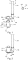
- Figure 1 shows an unshielded single core electric line 101 with a stranded wire conductor 102 surrounded by an insulating sheath 103. At one end of the line 101 the sheath 103 is removed and a cable shoe 104 is mechanically and electrically connected to the conductor 102 by a crimp sleeve 105.
- the cable shoe 104 further comprises a terminal lug 106 including a through hole 107 surrounded by a rim 108.
- the terminal lug 106 is bent by 90° relative to a longitudinal axis of the line 101.
- Figure 1 displays a connection bolt 111 comprising a shaft 112 and a head 113.
- the diameter of the head 113 is bigger than the diameter of the shaft 112.
- the head forms a shoulder 114 offering an abutment for the cable shoe 104 if placed on the shaft 112 of the connection bolt 111.
- the size of the through hole 107 is adapted to receive the shaft 112 of the connection bolt but does not allow the passage of the head 113.
- the shaft 112 further carries spring contacts 116 that can be deflected by the rim 108 when the connection bolt 111 is pushed through the through hole 107 of the terminal lug 106 as it is indicated by arrow 117.
- connection bolt 111 is made from copper, bronze or any other suitable electrically conducting material.
- the spring contacts 116 are made for instance from spring bronze or another elastic and electrically conducting material.
- Figure 2 illustrates the connection bolt 111 inserted into the through hole 107 of the cable shoe 104 in its end position.
- the connection bolt 111 allows for accepting a plurality of terminal lugs 106 because the thickness of the terminal lugs 106 is thinner than the length of the distance between a free end of the spring contacts 116 and the shoulder 114 of the connection bolt 111.
- Figure 3 displays a perspective view of an embodiment of a splice arrangement 300 according to the present disclosure including four lines 301 connected to the connection bolt 111.
- the four lines 301 are offset from one another in circumferential direction by an azimuth angle of 90°. In case of other embodiments having 5, 6 etc. lines connected to the connection bolt 111, their azimuth angle offset would be reduced to 72°, 60° etc.
- All cable lugs 106 are pressed together by the spring contacts 116 arranged on the shaft 112 of the connection bolt 111.
- the spring contacts are arranged at an axial position on the shaft 112 such that the distance between the shoulder 114 formed by the head 113 of the connection bolt 111 and a free end of the spring contacts 116 (not visible in Figure 3 ) corresponds to the cumulative thickness of the terminal lugs 106 that are placed on the connection bolt 111.
- the offset in angular direction of the connected lines 301 reduces the required installation space and enables a compact design of the splice arrangement 300.
- Figure 4 shows a cross-sectional view of the splice arrangement 300 of Figure 3 .
- the terminal lugs 106 of the lines 301 are arranged next to each other and pressed together by the spring contacts 116. In this way a firm mechanical contact is achieved that secures at the same time a good electrical connection between all connected lines 301.
- Figure 4 also illustrates that the length of the connection bolt 111 and/or the axial position of the spring contacts 116 on the connection bolt 111 is chosen according to the number of terminal lugs 106 and the thickness of the terminal lugs 106, which are placed on the connection bolt 111.
- the splice arrangement 300 needs to be insulated and protected against environmental influences, especially against humidity.
- This is achieved by a shrink hood 501 which is placed over the splice arrangement 300 as shown in Figure 5 .
- the shrink hood 501 contains inside a thermoplastic glue 502 that melts when the shrink hood 501 is heated. When heated, the shrink hood 501 reduces its diameter and the molten thermoplastic glue flows into all intermediate spaces between the lines 301. In this way the contact area of the cable lugs 106 and the connection bolt 111 is hermetically separated from the environment.
- connection bolt 601 comprises a shaft 112 in the head 113.
- connection bolt 601 provides for one spring contact 116 for each terminal lug 106 to be connected with the connection bolt 601.
- the connection bolt 601 is provided with four spring contacts 116a-d located at equidistant angular positions around the circumference of the shaft 112. Hence, there is an angular offset of 90° between each one of the spring contacts 116a-d.
- the first spring contact 116a is attached to the shaft 112 of the connection bolt 601 such that a free end of the spring contact 116a contacts a terminal lug 106 put onto the connection bolt 601.
- the distance of the free end of the spring contact 116a and the shoulder 114 of the head 113 is d, which corresponds to the thickness of the terminal lug 106.
- the second spring contact 116b is offset by 90° in circumferential direction from the first spring contact 116a and has a distance of 2d from the shoulder 114. This allows for contacting a second terminal lug 106 which is put onto the connection bolt 601.
- the third spring contact 116c is offset by 90° in circumferential direction from the second spring contact 116b and has a distance of 3d from the shoulder 114.
- the fourth spring contact 116d (not visible in Figure 6A ) is offset by 90° in circumferential direction from the third spring contact 116c and has a distance of 4d from the shoulder 114. In this way it is possible to put four terminal lugs 106 onto the connection bolt 601 and each terminal lug is mechanically fixed and electrically connected by one of the spring contacts 116a-d.
- the spring contacts 116a-d are illustrated in Figure 6A only schematically.
- each terminal lug is provided with a recess 602 through which a preceding spring contact can pass without being actuated by the subsequent terminal lug.
- the modified terminal lug 106 is shown in Figure 6B .
- Figure 7 illustrates the flow diagram of a method for producing the splice arrangement 300. For the sake of brevity, the method is described in conjunction with the connection bolt 111.
- a connection bolt 111 is selected and held in a fixture in a machine.
- the connection bolt 111 is adapted to the number of lines to be connected with the connection bolt 111.
- step S2 the terminal lugs of the lines 101 are put onto the connection bolt 111.
- step S3 the shrinking hood 501 is placed over the splice arrangement 300 in step S3.
- step S4 the shrinking heart 501 is heated to hermetically encapsulate the splice arrangement 300.
- step S2 includes positioning the terminal lugs 106 such that the spring contact of the previous terminal lug is not actuated by the subsequent terminal lug. This is achieved by properly aligning the recess 602 with the spring contact of the previously mounted terminal lug.
Landscapes
- Engineering & Computer Science (AREA)
- Manufacturing & Machinery (AREA)
- Connections Effected By Soldering, Adhesion, Or Permanent Deformation (AREA)
- Processing Of Terminals (AREA)
Priority Applications (3)
| Application Number | Priority Date | Filing Date | Title |
|---|---|---|---|
| EP22306300.9A EP4333214A1 (fr) | 2022-09-01 | 2022-09-01 | Borne d'épissure et procédé de fabrication d'un agencement d'épissure |
| CN202311044624.9A CN117638526A (zh) | 2022-09-01 | 2023-08-18 | 拼接端子和用于制造拼接组件的方法 |
| US18/239,107 US20240079798A1 (en) | 2022-09-01 | 2023-08-28 | Splice Terminal and Method for Making a Splice Arrangement |
Applications Claiming Priority (1)
| Application Number | Priority Date | Filing Date | Title |
|---|---|---|---|
| EP22306300.9A EP4333214A1 (fr) | 2022-09-01 | 2022-09-01 | Borne d'épissure et procédé de fabrication d'un agencement d'épissure |
Publications (1)
| Publication Number | Publication Date |
|---|---|
| EP4333214A1 true EP4333214A1 (fr) | 2024-03-06 |
Family
ID=83361050
Family Applications (1)
| Application Number | Title | Priority Date | Filing Date |
|---|---|---|---|
| EP22306300.9A Pending EP4333214A1 (fr) | 2022-09-01 | 2022-09-01 | Borne d'épissure et procédé de fabrication d'un agencement d'épissure |
Country Status (3)
| Country | Link |
|---|---|
| US (1) | US20240079798A1 (fr) |
| EP (1) | EP4333214A1 (fr) |
| CN (1) | CN117638526A (fr) |
Citations (7)
| Publication number | Priority date | Publication date | Assignee | Title |
|---|---|---|---|---|
| WO2001069726A1 (fr) * | 2000-03-10 | 2001-09-20 | Smith Michael W | Deconnecteur pour cables de batterie |
| FR2882196A1 (fr) * | 2005-02-16 | 2006-08-18 | Valeo Electronique Sys Liaison | Cosse de liaisons electriques |
| US7351123B1 (en) * | 2007-02-21 | 2008-04-01 | Devin Winiecke | Electrical terminal splice |
| CN108461160A (zh) * | 2018-03-23 | 2018-08-28 | 中国科学院合肥物质科学研究院 | 一种适用于磁约束核聚变装置的新型陶瓷接线端子 |
| EP3451463A1 (fr) | 2017-09-04 | 2019-03-06 | Nexans | Système de branchement de conduites électriques |
| JP2020021680A (ja) * | 2018-08-02 | 2020-02-06 | 矢崎総業株式会社 | 端子接続構造、電気接続箱及びワイヤハーネス |
| US20210091486A1 (en) * | 2019-09-20 | 2021-03-25 | Tyco Electronics France Sas | Fastening Device |
Family Cites Families (1)
| Publication number | Priority date | Publication date | Assignee | Title |
|---|---|---|---|---|
| CN104898219A (zh) * | 2009-02-26 | 2015-09-09 | 戚郁芬 | 具弹性橡胶收缩管防水装置的通信光缆接续盒 |
-
2022
- 2022-09-01 EP EP22306300.9A patent/EP4333214A1/fr active Pending
-
2023
- 2023-08-18 CN CN202311044624.9A patent/CN117638526A/zh active Pending
- 2023-08-28 US US18/239,107 patent/US20240079798A1/en active Pending
Patent Citations (7)
| Publication number | Priority date | Publication date | Assignee | Title |
|---|---|---|---|---|
| WO2001069726A1 (fr) * | 2000-03-10 | 2001-09-20 | Smith Michael W | Deconnecteur pour cables de batterie |
| FR2882196A1 (fr) * | 2005-02-16 | 2006-08-18 | Valeo Electronique Sys Liaison | Cosse de liaisons electriques |
| US7351123B1 (en) * | 2007-02-21 | 2008-04-01 | Devin Winiecke | Electrical terminal splice |
| EP3451463A1 (fr) | 2017-09-04 | 2019-03-06 | Nexans | Système de branchement de conduites électriques |
| CN108461160A (zh) * | 2018-03-23 | 2018-08-28 | 中国科学院合肥物质科学研究院 | 一种适用于磁约束核聚变装置的新型陶瓷接线端子 |
| JP2020021680A (ja) * | 2018-08-02 | 2020-02-06 | 矢崎総業株式会社 | 端子接続構造、電気接続箱及びワイヤハーネス |
| US20210091486A1 (en) * | 2019-09-20 | 2021-03-25 | Tyco Electronics France Sas | Fastening Device |
Also Published As
| Publication number | Publication date |
|---|---|
| US20240079798A1 (en) | 2024-03-07 |
| CN117638526A (zh) | 2024-03-01 |
Similar Documents
| Publication | Publication Date | Title |
|---|---|---|
| US9419491B2 (en) | Motor connecting member and motor device | |
| US8159099B2 (en) | Stator having busbars for connection of the coils, and a corresponding method | |
| EP3840134B1 (fr) | Connecteur électrique | |
| US6193564B1 (en) | Electric connecting configuration | |
| WO2009113686A1 (fr) | Matériau de cerclage, procédé de fabrication de borne conductrice interne, et connecteur coaxial | |
| US20170302130A1 (en) | Motor with wiring board formed by crimp-connecting winding | |
| US9065233B2 (en) | Terminal connection structure and method of manufacturing the same | |
| JP4597516B2 (ja) | フレキシブル電気配線 | |
| JPS6380492A (ja) | コネクタの結線方法 | |
| US20120103647A1 (en) | Electrical connecting cable | |
| US10566709B2 (en) | Electrical connector having an electrical device mounted to a flexible carrier | |
| CN103688416A (zh) | 电接触元件 | |
| EP4333214A1 (fr) | Borne d'épissure et procédé de fabrication d'un agencement d'épissure | |
| WO2017131935A1 (fr) | Ensemble de connexion de câble blindé | |
| US11205865B2 (en) | Multi-part wire terminal with sealing member | |
| CN110431642B (zh) | 导电线 | |
| JP2010040214A (ja) | 集合ケーブルの接地部材及び接地方法並びに集合ケーブル組立体 | |
| WO2009142273A1 (fr) | Élément de connexion | |
| JP2020064831A (ja) | 接続装置、プラグおよびソケット | |
| JP2009037748A (ja) | ケーブルコネクタ及びケーブル接続方法 | |
| JP7810034B2 (ja) | 平型電線及び端子付き平型電線 | |
| JP6939584B2 (ja) | 樹脂成形体付きケーブルの製造方法 | |
| JP5325698B2 (ja) | 電線接続ユニット | |
| JP4503458B2 (ja) | シールド電線のアース接続具およびアース接続方法 | |
| JP2020027776A (ja) | 複合ケーブル |
Legal Events
| Date | Code | Title | Description |
|---|---|---|---|
| PUAI | Public reference made under article 153(3) epc to a published international application that has entered the european phase |
Free format text: ORIGINAL CODE: 0009012 |
|
| STAA | Information on the status of an ep patent application or granted ep patent |
Free format text: STATUS: THE APPLICATION HAS BEEN PUBLISHED |
|
| AK | Designated contracting states |
Kind code of ref document: A1 Designated state(s): AL AT BE BG CH CY CZ DE DK EE ES FI FR GB GR HR HU IE IS IT LI LT LU LV MC MK MT NL NO PL PT RO RS SE SI SK SM TR |
|
| STAA | Information on the status of an ep patent application or granted ep patent |
Free format text: STATUS: REQUEST FOR EXAMINATION WAS MADE |
|
| 17P | Request for examination filed |
Effective date: 20240906 |
|
| RBV | Designated contracting states (corrected) |
Designated state(s): AL AT BE BG CH CY CZ DE DK EE ES FI FR GB GR HR HU IE IS IT LI LT LU LV MC MK MT NL NO PL PT RO RS SE SI SK SM TR |
|
| GRAP | Despatch of communication of intention to grant a patent |
Free format text: ORIGINAL CODE: EPIDOSNIGR1 |
|
| STAA | Information on the status of an ep patent application or granted ep patent |
Free format text: STATUS: GRANT OF PATENT IS INTENDED |
|
| INTG | Intention to grant announced |
Effective date: 20260107 |
|
| RIC1 | Information provided on ipc code assigned before grant |
Ipc: H01R 4/34 20060101AFI20251219BHEP Ipc: H01R 11/12 20060101ALI20251219BHEP Ipc: H01R 11/32 20060101ALI20251219BHEP Ipc: H01R 4/72 20060101ALN20251219BHEP Ipc: H01R 4/48 20060101ALN20251219BHEP |