EP4333575B1 - Eingangskühlkörper für ein kühlsystem einer elektronischen superrechnerkarte - Google Patents
Eingangskühlkörper für ein kühlsystem einer elektronischen superrechnerkarte Download PDFInfo
- Publication number
- EP4333575B1 EP4333575B1 EP22306291.0A EP22306291A EP4333575B1 EP 4333575 B1 EP4333575 B1 EP 4333575B1 EP 22306291 A EP22306291 A EP 22306291A EP 4333575 B1 EP4333575 B1 EP 4333575B1
- Authority
- EP
- European Patent Office
- Prior art keywords
- heat sink
- cold
- inlet
- connector
- heat
- Prior art date
- Legal status (The legal status is an assumption and is not a legal conclusion. Google has not performed a legal analysis and makes no representation as to the accuracy of the status listed.)
- Active
Links
Images
Classifications
-
- H—ELECTRICITY
- H05—ELECTRIC TECHNIQUES NOT OTHERWISE PROVIDED FOR
- H05K—PRINTED CIRCUITS; CASINGS OR CONSTRUCTIONAL DETAILS OF ELECTRIC APPARATUS; MANUFACTURE OF ASSEMBLAGES OF ELECTRICAL COMPONENTS
- H05K7/00—Constructional details common to different types of electric apparatus
- H05K7/20—Modifications to facilitate cooling, ventilating, or heating
- H05K7/20709—Modifications to facilitate cooling, ventilating, or heating for server racks or cabinets; for data centers, e.g. 19-inch computer racks
- H05K7/20763—Liquid cooling without phase change
- H05K7/20772—Liquid cooling without phase change within server blades for removing heat from heat source
-
- H—ELECTRICITY
- H05—ELECTRIC TECHNIQUES NOT OTHERWISE PROVIDED FOR
- H05K—PRINTED CIRCUITS; CASINGS OR CONSTRUCTIONAL DETAILS OF ELECTRIC APPARATUS; MANUFACTURE OF ASSEMBLAGES OF ELECTRICAL COMPONENTS
- H05K1/00—Printed circuits
- H05K1/02—Details
- H05K1/0201—Thermal arrangements, e.g. for cooling, heating or preventing overheating
- H05K1/0203—Cooling of mounted components
-
- G—PHYSICS
- G06—COMPUTING OR CALCULATING; COUNTING
- G06F—ELECTRIC DIGITAL DATA PROCESSING
- G06F1/00—Details not covered by groups G06F3/00 - G06F13/00 and G06F21/00
- G06F1/16—Constructional details or arrangements
- G06F1/20—Cooling means
-
- H—ELECTRICITY
- H05—ELECTRIC TECHNIQUES NOT OTHERWISE PROVIDED FOR
- H05K—PRINTED CIRCUITS; CASINGS OR CONSTRUCTIONAL DETAILS OF ELECTRIC APPARATUS; MANUFACTURE OF ASSEMBLAGES OF ELECTRICAL COMPONENTS
- H05K7/00—Constructional details common to different types of electric apparatus
- H05K7/20—Modifications to facilitate cooling, ventilating, or heating
- H05K7/20218—Modifications to facilitate cooling, ventilating, or heating using a liquid coolant without phase change in electronic enclosures
- H05K7/20254—Cold plates transferring heat from heat source to coolant
-
- H—ELECTRICITY
- H05—ELECTRIC TECHNIQUES NOT OTHERWISE PROVIDED FOR
- H05K—PRINTED CIRCUITS; CASINGS OR CONSTRUCTIONAL DETAILS OF ELECTRIC APPARATUS; MANUFACTURE OF ASSEMBLAGES OF ELECTRICAL COMPONENTS
- H05K7/00—Constructional details common to different types of electric apparatus
- H05K7/20—Modifications to facilitate cooling, ventilating, or heating
- H05K7/20218—Modifications to facilitate cooling, ventilating, or heating using a liquid coolant without phase change in electronic enclosures
- H05K7/20263—Heat dissipaters releasing heat from coolant
-
- H—ELECTRICITY
- H05—ELECTRIC TECHNIQUES NOT OTHERWISE PROVIDED FOR
- H05K—PRINTED CIRCUITS; CASINGS OR CONSTRUCTIONAL DETAILS OF ELECTRIC APPARATUS; MANUFACTURE OF ASSEMBLAGES OF ELECTRICAL COMPONENTS
- H05K7/00—Constructional details common to different types of electric apparatus
- H05K7/20—Modifications to facilitate cooling, ventilating, or heating
- H05K7/20218—Modifications to facilitate cooling, ventilating, or heating using a liquid coolant without phase change in electronic enclosures
- H05K7/20272—Accessories for moving fluid, for expanding fluid, for connecting fluid conduits, for distributing fluid, for removing gas or for preventing leakage, e.g. pumps, tanks or manifolds
-
- G—PHYSICS
- G06—COMPUTING OR CALCULATING; COUNTING
- G06F—ELECTRIC DIGITAL DATA PROCESSING
- G06F2200/00—Indexing scheme relating to G06F1/04 - G06F1/32
- G06F2200/20—Indexing scheme relating to G06F1/20
- G06F2200/201—Cooling arrangements using cooling fluid
Definitions
- the present invention relates to the field of cooling computer processors and more particularly concerns a liquid cooling system for an electronic card comprising at least one calculation processor.
- IBM ® has developed a mixed cooling system for dual-processor electronic cards for supercomputers.
- Such a system includes copper pipes containing a heat transfer fluid forming a liquid loop.
- the rigidity of the copper pipes does not allow for the rapid disassembly of a single processor.
- the liquid loop provides cooling for the processors only. The rest of the dissipated power is cooled by convection in the air, which is not optimal for the energy efficiency (PUE, acronym for "Power Usage Effectiveness”) of the supercomputer.
- PUE acronym for "Power Usage Effectiveness
- the applicant has also developed a mixed cooling system in which the electronic cards are cooled by means of an aluminium cold plate in which a heat transfer fluid circulates, the cold plate being interfaced with all the low and medium electronic components to be cooled, i.e. all the components of an electronic card excluding the high electronic components (typically processors and memory strips).
- the processors are the components that are the most difficult to cool (because they must remain accessible) and also the most dissipative. They cannot be interfaced with the cold plate directly.
- each of them is interfaced with an intermediate heat sink with heat pipes. This is a two-phase heat sink with phase change (generally referred to in English as "Heat Spreader CPU"), which conducts the heat from the processors to the cold plate.
- thermal limits specific to heat pipes the flow inside a heat pipe is two-phase and is governed by five limits in terms of flow, viscosity, boiling, entrainment, capillarity, which depend on the dimensions of the heat pipes and the power to be evacuated.
- thermal contacts must be ensured between the cold plate and the heat sink on the one hand, and between the heat sink and the processor. These thermal contacts are, in the current solution implemented by the applicant, guaranteed by the use of conductive grease, which has the disadvantage of generating a high temperature gradient.
- a cooling system for an electronic card that is entirely liquid, comprising a cold plate supplied with heat transfer fluid via a water path internal to the cold plate, and a plurality of heat sinks connected in flexible connections with the water path internal to the cold plate.
- These flexible connections form a flexible network coupled to the network of rigid channels of the cold plate supplied with heat transfer fluid (typically glycolated water), thus allowing the heat transfer fluid to be supplied to the heat sinks.
- This network is coupled to the cold plate system allowing the cooling of the rest of the electronic card.
- the heat transfer fluid must be brought as close as possible to the heat source.
- a single-phase heat sink comprising a cooling block made of thermally conductive material that can be supplied with heat transfer fluid.
- the heat source that constitutes the processor will therefore be directly interfaced with this cooling block (also referred to in the examples by the term in English "waterblock”) supplied with heat transfer fluid taken from the cold plate.
- This solution is described in detail in the document WO2019115963 .
- the heat exchangers 100 are connected in series, that is to say that the inlet of the first exchanger 100 is connected to a liquid inlet via an inlet hose 101, its outlet is connected to the inlet of the next exchanger 100 via a connecting hose 102 and so on until the outlet of the last exchanger 100 which is connected to a liquid outlet via an outlet hose 103.
- the temperature of the liquid increases as it approaches the liquid outlet (the liquid is hotter when it arrives in the last exchanger since it has already been used to cool the previous exchangers) and therefore the components located at the end of the chain are less well cooled than those at the beginning of the chain.
- this solution makes maintenance of the components complicated since it is necessary to dismantle all the exchangers in flexible connection to change a component of the chain, in particular beyond two exchangers in series.
- An aim of the invention is therefore to provide a cooling solution for an electronic card, in particular a supercomputer.
- the invention defines several types of complementary heat sinks, each having a specific function, as well as a cooling system comprising such sinks.
- the inlet heat sink according to the invention thus makes it possible to retain part of the cold flow coming from the cold plate to direct it towards another heat sink connected to its output, thus improving the cooling of the electronic component(s) (processor or other) located downstream in the direction of circulation of the heat transfer fluid.
- the inlet heat sink according to the invention also makes it possible to meet mass production constraints, due to its simplicity of manufacture.
- the outlet heat sink according to the invention thus makes it possible to both receive a flow of cold heat transfer fluid and to merge the hot flows coming from both the lower part of the cooling block and an upstream heat sink connected to the hot inlet of said outlet heat sink, thus improving the cooling of the electronic component(s) associated with said outlet heat sink while allowing the circulation of the heat transfer fluid.
- the outlet heat sink according to the invention also makes it possible to meet mass production constraints, due to its simplicity of manufacture.
- an input heat sink may be connected in pairs with an output heat sink to form a heat sink assembly according to the invention.
- the invention also relates to a liquid cooling system for an electronic card, said card comprising at least one electronic component, for example a processor, a voltage regulator or a memory strip, for example mounted on a support, said system comprising a cold plate and at least one set of heat sinks, the cold plate being intended to receive said set of heat sinks, being sized to at least partially cover the electronic card, in particular the support of the at least one electronic component where appropriate, and comprising a cooling circuit comprising channels inside which circulates a so-called "cold" heat transfer fluid, intended to supply at least one of the heat sinks, and an evacuation circuit comprising channels inside which circulates a so-called "hot” heat transfer fluid having heated up through at least one of the heat sinks, each heat sink comprising a main heat exchange zone capable of coming to bear against one of the processors, each set of heat sinks comprising an input heat sink as presented above and an output heat sink as presented above, the input connector of the input heat sink being fluidically connected to the cooling circuit by an inlet tube, the cold output
- the system according to the invention thus makes it possible to effectively cool the electronic card by distributing the cold heat transfer fluid between the inlet heat sink and the outlet heat sink of the same set of heat sinks.
- the cooling system according to the invention makes it possible to guarantee the cooling of the components of the electronic card, and this by liquid means whatever the nature of the electronic components: the low and medium components by the cold plate and the so-called high components such as the processors and the memory strips by the heat sinks, in particular single-phase, with cooling block.
- the cooling system according to the invention due to its structure with cooling blocks connected in flexible connections with the cooling circuit of the cold plate allows great flexibility for the disassembly of the processors and guarantees reliability of the connections after a large number of disassembly operation cycles.
- a seal at 10 bars is guaranteed by the cooling system according to the invention, including after several disassembly operations.
- the cooling system according to the invention due to its structure with cooling blocks connected in flexible connections with the cooling circuit of the cold plate, allows the installation of a plurality of heat sinks in series or in parallel, for example six in number.
- the hot output connector of the input heat sink is connected to the hot input connector of the output heat sink by a first flexible and/or straight connecting tube and the cold output connector of the heat sink
- the input thermal is connected to the cold input connector of the output heat sink by a second flexible and/or straight connecting tube.
- first connecting tube and the second connecting tube are straight, they are arranged parallel to each other in order to optimize space and thus reduce the volume of the system.
- the at least one heat sink assembly includes an interposed heat sink as described above, fluidly connected to the hot output connector and the cold output connector of the input heat sink and to the hot input connector and the cold input connector of the output heat sink.
- the system may include a plurality of heat sink assemblies, preferably arranged parallel to each other in order to optimize space and thereby reduce the volume of the system.
- the inlet tube of each inlet heat sink is flexible to facilitate assembly by flexible connections with the cold plate.
- the outlet tube of each outlet heat sink is flexible to facilitate assembly by flexible connections with the cold plate.
- the at least one intermediate heat sink is connected to the input heat sink and/or to the output heat sink via flexible and/or straight connecting tubes.
- the invention also relates to a method for separating a flow of so-called "cold" heat transfer fluid in an input heat sink as presented above for a liquid cooling system of an electronic card, said card comprising at least one electronic component, for example a processor, a voltage regulator or a memory strip, for example mounted on a support, said system comprising a cold plate intended to receive said heat sink, said cold plate being sized to at least partially cover the electronic card, in particular the support of the at least one electronic component where appropriate, and comprising a cooling circuit comprising channels inside which circulates a so-called “cold” heat transfer fluid, intended to supply at least said heat sink, and an evacuation circuit comprising channels inside which circulates a so-called "hot” heat transfer fluid having heated up through the heat sink, said method comprising the steps of supplying the cold input connector by the heat transfer fluid coming from the cold plate and dividing said flow of heat transfer fluid entering through the cold inlet connector into a first flow, which is oriented towards the lower part of the cooling block so as to collect the heat generated by
- the invention also relates to a method for merging a flow of heat transfer fluid in an output heat sink as presented above for a liquid cooling system of an electronic card, said card comprising at least one electronic component, for example a processor, a voltage regulator or a memory strip, for example mounted on a support, said system comprising a cold plate intended to receive said heat sink, said cold plate being sized to at least partially cover the electronic card, in particular the support of the at least one electronic component where appropriate, and comprising a cooling circuit comprising channels inside which circulates a so-called "cold" heat transfer fluid, intended to supply said heat sink, and an evacuation circuit comprising channels inside which circulates a so-called "hot” heat transfer fluid having heated up through the heat sink, the method comprising the steps of supplying the cold input connector with the cold heat transfer fluid, of supplying the hot input connector with a flow of heat transfer fluid heated, routing the flow of heat transfer fluid entering through the cold inlet connector to the lower part of the cooling block so as to collect the heat generated by the electronic card by being routed
- the heat sink of the cooling system according to the invention must itself comply with a space constraint defined by the size of the components (processors or others) and by the space available on the cold plates to judiciously distribute the cooling fluid.
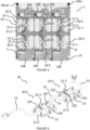
- FIG. 3 illustrates an example of system 1 according to the invention.
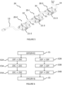
- the system 1 allows the liquid cooling of an electronic card 5 (visible partly in transparency) and comprises for this purpose a cold plate 10 and sets 20 of heat sinks 20-E, 20-S, one of which is shown in isolation (and partially) on the figure 4 .
- the electronic card 5 comprises in this example six processors mounted on a support (not visible) of the electronic card 5.
- the electronic card 5 comprises a plurality of electronic components fixed on the support, broken down for example into low and medium electronic components and into high electronic components comprising the processors.
- low and medium electronic components we mean, within the meaning of the present invention, any component of the electronic card 5 having a height lower than a threshold height, below which it can be cooled by the cooling circuit of the cold plate 10.
- these are generally power supplies or voltage regulators.
- any component of the electronic card 5 which is not cooled by the cooling circuit of the cold plate 10 because they must remain accessible without dismantling the cold plate 10.
- These are electronic components requiring rapid maintenance such as processors or memory strips.
- the system 1 comprises, in addition to the cold plate 10, three sets 20 of heat sinks 20-E, 20-S arranged parallel to each other and each comprising an input heat sink 20-E and an output heat sink 20-S.
- the cold plate 10 is sized to cover the processor support.
- the cold plate 10 has exterior dimensions substantially equal to those of said support of the electronic card 5 so that it covers the entire support and the low and medium electronic components.
- the cold plate 10 comprises a cooling circuit 10R and an evacuation circuit 10E.
- the cooling circuit 10R comprises channels, preferably rigid, inside which circulates a so-called “cold” heat transfer fluid for supplying the inlet heat sinks.
- the evacuation circuit 10E comprises channels inside which circulates a so-called “hot” heat transfer fluid having heated up through the heat sinks 20-E, 20-S.
- the supply of cold heat transfer fluid to the cold plate 10 is carried out via an inlet connector 10in and the outlet of the heated heat transfer fluid from the cold plate 10 is via an outlet connector 10out.
- 20-E, 20-S heat sinks can be single-phase type.
- Each heat sink 20-E, 20-S comprises a main heat exchange zone capable of coming to bear against a high electronic component, in particular one of the processors, or a low electronic component, in particular the voltage regulators and/or the memory strips.
- each heat sink 20-E, 20-S comprises a cooling block 21, at least one input connector 22C, 22F and at least one output connector 23C, 23F (depending on the type of heat sink 20-E, 20-S).
- the cooling block 21 is made of a heat-conducting material such as, for example, aluminum or aluminum alloy.
- the cooling block 21 comprises a lower part 21-1 constituting the main heat exchange zone, an intermediate part 21-2 called “distribution” (optional) and an upper part 21-3 connected to the cold plate 10.
- the cooling block 21 comprises a through slot located in the intermediate portion to homogeneously distribute the flow of the heat transfer fluid from the upper portion in the form of a centered jet toward a support plate located in the main heat exchange zone and comprising a hollow central portion with a zone provided with fins or spikes to generate turbulence in the flow regime of said heat transfer fluid and a zone peripheral to said zone provided with fins or spikes to collect the heat transfer fluid and direct it toward said outlet connector.
- the slot is thin.
- the heat transfer fluid when it arrives in the cooling block 21, passes through the fine slot, which allows its equitable distribution in the exchange surface through the fins.
- the shape of this distributor and its distance from the fins are studied so as to obtain the largest possible Reynolds number in the available space.
- each 20-E input heat sink includes a so-called “cold” input connector 22F, a so-called “hot” output connector 23C and a so-called “cold” output connector 23F.
- the cold inlet connector 22F is fluidically connected to the upper part of the cooling block 21 and receives an inlet tube 13, preferably flexible, connected to the cooling circuit 10R to supply the cooling block 21 with the heat transfer fluid coming from the cold plate 10.
- the upper portion of the cooling block 21 is configured to divide the flow of heat transfer fluid entering through the cold inlet connector 22F into a first flow and a second flow. Preferably, this division is achieved by implementing a Tickelman loop, known per se, at the cooling block 21.
- the first flow is directed towards the lower part of the cooling block 21 so as to collect the heat generated by the electronic card 5 by being routed to the hot output connector 23C.
- the second stream is directed directly to the 23F cold output connector.
- Each 20-S output heat sink includes a 22C "hot” input connector, a 22F “cold” input connector, and a 23C "hot” output connector.
- the hot inlet connector 22C is fluidically connected to the upper part of the cooling block 21 and receives a first connecting tube 31, preferably flexible, of a flow of heat transfer fluid heated by the inlet heat sink 20-E, connected to the hot outlet connector 23C of the inlet heat sink 20-E.
- the cold inlet connector 22F is fluidically connected to the upper part of the cooling block 21 and receives a second connecting tube 32, preferably flexible, connected to the cold outlet connector of the inlet heat sink 20-E, so that that the cooling block 21 is supplied with the heat transfer fluid coming from the cold plate 10 through the inlet heat sink 20-E, in particular from the cold outlet connector 23F of the inlet heat sink 20-E.
- the upper part of the cooling block 21 is configured to, on the one hand, route the flow of heat transfer fluid entering through the cold inlet connector 22F to the lower part of the cooling block 21 so as to collect the heat generated by the electronic card 5 by being routed to the hot outlet connector 23C, and on the other hand, route the flow of heated heat transfer fluid received on the hot inlet connector 22C directly to the hot outlet connector 23C.
- this fusion is carried out by implementing a Tickelman loop, known per se, at the cooling block 21.
- the hot output connector 23C of the output heat sink 20-S is connected to the cold plate exhaust circuit by an output tube 14.
- each heat sink assembly further includes an interposed heat sink 20-I, fluidly connected on the one hand to the hot output connector 23C and the cold output connector 23F of the input heat sink 20-E and on the other hand to the hot input connector 22C and the cold input connector 22F of the output heat sink 20-S.
- This configuration allows cooling a 3 x 3 (i.e. 9) (or more) processor array simultaneously.
- the intercalated heat sink 20-I comprises a so-called "cold” inlet connector 22F intended to be fluidically connected to the cold outlet connector 23F of the inlet heat sink 20-E and fluidly connected to the upper part 21-3 of said cooling block 21 so that said cooling block 21 is supplied with the cold heat transfer fluid.
- the intercalated heat sink 20-I comprises a so-called "hot” inlet connector 22C intended to be fluidically connected to the hot outlet connector 23C of the inlet heat sink 20-E and fluidly connected to the upper part 21-3 of said cooling block 21.
- the intercalated heat sink 20-I comprises a so-called "hot” outlet connector 23C intended to be fluidically connected to the hot inlet connector 22C of the outlet heat sink 20-S.
- the intercalated heat sink 20-I comprises a so-called "cold" outlet connector 23F intended to be fluidically connected to the cold inlet connector 22F of the outlet heat sink 20-S.
- the upper portion 21-3 of the cooling block 21 is configured to divide the flow of heat transfer fluid entering through the cold inlet connector 22F into a first flow, which is oriented towards the lower part 21-1 of the cooling block 21 so as to collect the heat generated by the electronic card 5 by being routed to the hot output connector 23C, and a second flow, oriented directly towards the cold output connector 23F, and route the flow of heated heat transfer fluid received on the hot input connector 22C directly to the hot output connector 23C.
- system 1 could include more or less than three sets of heat sinks and each set of heat sinks could include, in addition to an input heat sink 20-E and an output heat sink 20-S, one or more interposed heat sinks 20-I, connected in series.
- the heat transfer fluid circulating in the cold plate cooling circuit, before entering the inlet heat sinks, is said to be “cold”.
- the heat transfer fluid circulating in the cold plate discharge circuit after passing through the heat sink assemblies is said to be "hot”.
- a step E1 the cold heat transfer fluid is conveyed by the cooling circuit to the cold inlet connector 22F of each inlet heat sink 20-E in order to supply it.
- Each inlet heat sink 20-E divides the flow of cold heat transfer fluid entering through the cold inlet connector 22F into a first flow and a second flow, substantially equal in flow rate, said flow rate being of the order of half the flow rate of the incoming flow.
- the first flow is directed from the cold inlet connector 22F to the lower part 21-3 of the cooling block 21 in a step E2A so as to collect the heat generated by the electronic card 5 and then to be routed to the hot outlet connector 23C.
- the second flow is directed in a step E2B directly towards the cold output connector 23F without passing through the lower part 21-3 of the cooling block 21 and therefore without undergoing heating by the electronic card 5.
- a step E3A the first heated flow is routed from the hot output connector 23C of the input heat sink 20-E to the hot input connector 22C of the output heat sink 20-S via the first connecting tube 31.
- a step E3B the second flow, composed of cold heat transfer fluid, is routed to the inlet of the cold inlet connector 22F of the outlet heat sink 20-S.
- a step E4A the heated heat transfer fluid flow is transferred directly from the hot inlet connector 22C of the outlet heat sink 20-S to the hot outlet connector 23C of the outlet heat sink 20-S.
- a step E4B the second flow is routed to the lower part 21-3 of the cooling block 21 of the output heat sink 20-S so as to collect the heat generated by the electronic card 5, then to the hot output connector 23C of the output heat sink 20-S where it mixes, in a step E5, with the flow of heated heat transfer fluid provided by the step E4A, so as to return to the initial flow rate of the input flow of the step E1.
- the invention makes it possible to arrange the sets 20 of heat sinks 20-E, 20-S in parallel by reducing the number of inlet tubes 13 and outlet tubes 14 while allowing easy maintenance.
Landscapes
- Engineering & Computer Science (AREA)
- Microelectronics & Electronic Packaging (AREA)
- Physics & Mathematics (AREA)
- Thermal Sciences (AREA)
- General Engineering & Computer Science (AREA)
- Theoretical Computer Science (AREA)
- Human Computer Interaction (AREA)
- General Physics & Mathematics (AREA)
- Computer Hardware Design (AREA)
- Cooling Or The Like Of Electrical Apparatus (AREA)
- Cooling Or The Like Of Semiconductors Or Solid State Devices (AREA)
Claims (10)
- Einlasswärmesenke (20-E) für ein Flüssigkeitskühlungssystem (1) einer Elektronikkarte (5), wobei die Elektronikkarte (5) mindestens eine Elektronikkomponente aufweist, das System (1) umfassend eine Kühlplatte (10), die dazu bestimmt ist, die Wärmesenke (20-E) aufzunehmen, wobei die Kühlplatte (10) zum Bedecken mindestens teilweise der Elektronikkarte (5) bemessen ist, und umfassend einen Kühlkreislauf (10R), der Kanäle aufweist, in denen ein sogenanntes "kühles" Wärmeübertragungsfluid zirkuliert, das dazu bestimmt ist, mindestens die Wärmesenke (20-E) zu versorgen, und einen Ableitungskreislauf (10E), der Kanäle aufweist, in denen sogenanntes "heißes" Wärmeübertragungsfluid zirkuliert, das sich durch die Wärmesenke (20-E) erhitzt hat, die Wärmesenke (20-E) umfassend einen Kühlblock (21), umfassend einen unteren Teil (21-1), der die Hauptwärmeaustauschzone bildet, und einen oberen Teil (21-3), der dazu bestimmt ist, an die Kühlplatte (10) angeschlossen zu werden, wobei die Wärmesenke (20-E) dadurch gekennzeichnet ist, dass sie umfasst:- einen sogenannten "kühlen" Einlassanschluss (22F), der mit dem oberen Teil des Kühlblocks (21) fluidverbunden ist und der dazu bestimmt ist, ein Einlassrohr (13) des Kühlkreislaufs (10R) aufzunehmen, sodass der Kühlblock (21) mit dem Wärmeübertragungsfluid versorgt wird, das von der Kühlplatte (10) kommt,- einen sogenannten "heißen" Auslassanschluss (23C),- einen sogenannten "kühlen" Auslassanschluss (23F),wobei der obere Teil (21-3) des Kühlblocks (21) zum Aufteilen des Wärmeübertragungsfluidstroms, der durch den kühlen Einlassanschluss (22F) eintritt, in einen ersten Strom, der zu dem unteren Teil (21-1) des Kühlblocks (21) gelenkt wird, um die Hitze zu sammeln, die durch die Elektronikkarte (5) erzeugt wird, indem er bis zu dem heißen Auslassanschluss (23C) befördert wird, und einen zweiten Strom, der direkt zu dem kalten Auslassanschluss (23F) gelenkt wird, konfiguriert ist.
- Einlasswärmesenke (20-E) nach Anspruch 1, wobei die Elektronikkomponente ein Prozessor, ein Spannungsregler oder ein Speichermodul ist.
- Einlasswärmesenke (20-E) nach einem der Ansprüche 1 oder 2, wobei der Kühlblock (21) aus einem wärmeleitenden Material hergestellt ist.
- Flüssigkeitskühlungssystem (1) einer Elektronikkarte (5), wobei die Elektronikkarte (5) mindestens eine Elektronikkomponente aufweist, das System (1) umfassend eine Kühlplatte (10) und mindestens einen Satz von Wärmesenken (20-E, 20S), wobei die Kühlplatte (10) zum Aufnehmen des Satzes von Wärmesenken (20-E, 20S) konfiguriert ist, zum Bedecken mindestens teilweise der Elektronikkarte (5) bemessen ist, und umfassend einen Kühlkreislauf (10R), der Kanäle aufweist, in denen ein sogenanntes "kühles" Wärmeübertragungsfluid zirkuliert, das dazu bestimmt ist, mindestens eine der Wärmesenken (20-E, 20S) zu versorgen, und einen Ableitungskreislauf (10E), der Kanäle aufweist, in denen ein sogenanntes "heißes" Wärmeübertragungsfluid zirkuliert, das sich durch mindestens eine der Wärmesenken (20-E, 20S) erhitzt hat, jede Wärmesenke (20-E, 20S) umfassend eine Hauptwärmeaustauschzone, die geeignet ist, um an einer der Elektronikkomponenten anzuliegen, jeder Satz von Wärmesenken (20-E, 20S) umfassend eine Einlasswärmesenke (20-E) nach einem der Ansprüche 1 bis 3 und eine Auslasswärmesenke (20S), umfassend einen Kühlblock (21), der einen unteren Teil (21-1), der die Hauptwärmeaustauschzone bildet, und einen oberen Teil (21-3), der dazu bestimmt ist, an die Kühlplatte (10) angeschlossen zu werden, aufweist, die Auslasswärmesenke (20S) umfassend:- einen sogenannten "kühlen" Einlassanschluss (22F), der mit dem oberen Teil (21-3) des Kühlblocks (21) fluidverbunden ist und ein Verbindungsrohr (32) des Kühlkreislaufs (10R) aufnimmt, sodass der Kühlblock (21) mit dem Wärmeübertragungsfluid, das von der Kühlplatte (10) kommt, durch die Einlasswärmesenke (20-E) versorgt wird,- einen sogenannten "heißen" Einlassanschluss (22C), der mit dem oberen Teil (21-3) des Kühlblocks (21) fluidverbunden ist und der dazu bestimmt ist, ein Verbindungsrohr (31) eines erhitzten Wärmeübertragungsfluidstroms aufzunehmen,- einen sogenannten "heißen" Auslassanschluss (23C),wobei der obere Teil (21-3) des Kühlblocks (21) zum einerseits Befördern des Wärmeübertragungsfluidstroms, der durch den kühlen Einlassanschluss (22F) eintritt, zu dem unteren Teil (21-1) des Kühlblocks (21), um die Hitze zu sammeln, die durch die Elektronikkarte (5) erzeugt wird, indem er bis zu dem heißen Auslassanschluss (23C) befördert wird, und andererseits Befördern des erhitzten Wärmeübertragungsfluidstroms, der an dem heißen Einlassanschluss (22C) aufgenommen wird, direkt zu dem heißen Auslassanschluss (23C) konfiguriert ist, wobei der kühle Einlassanschluss (22F) der Einlasswärmesenke (20-E) über ein Einlassrohr (13) mit dem Kühlkreislauf (10R) fluidverbunden ist, wobei der kühle Auslassanschluss (23F) der Einlasswärmesenke (20-E) mit dem kühlen Einlassanschluss (22F) der Auslasswärmesenke (20-S) fluidverbunden ist, wobei der heiße Auslassanschluss (23C) der Einlasswärmesenke (20-E) mit dem heißen Einlassanschluss (22C) der Auslasswärmesenke (20-S) fluidverbunden ist, wobei der heiße Auslassanschluss (23C) der Auslasswärmesenke (20-S) über ein Auslassrohr (14) mit dem Ableitungskreislauf (10E) verbunden ist.
- System (1) nach Anspruch 4, wobei der heiße Auslassanschluss (23C) der Einlasswärmesenke (20-E) mit dem heißen Einlassanschluss (22C) der Auslasswärmesenke (20-S) durch ein erstes flexibles und/oder geradliniges Verbindungsrohr (31) verbunden ist und der kühle Ausgangsanschluss (23F) der Einlasswärmesenke (20-E) mit dem kühlen Einlassanschluss (22F) der Auslasswärmesenke (20-S) über ein zweites flexibles und/oder geradliniges Verbindungsrohr (32) verbunden ist.
- System (1) nach Anspruch 4, wobei der mindestens eine Satz von Wärmesenken (20-E, 20-S) eine Zwischenwärmesenke (20-I) umfasst, umfassend einen Kühlblock (21), der einen unteren Teil (21-1), der die Hauptwärmeaustauschzone bildet, und einen oberen Teil (21-3), der dazu bestimmt ist, an die Kühlplatte (10) angeschlossen zu werden, aufweist, die Zwischenwärmesenke (20-I) umfassend:- einen sogenannten "kühlen" Einlassanschluss (22F), der an den kühlen Ausgangsanschluss (23F) der Einlasswärmesenke (20-E) fluidisch angeschlossen ist und mit dem oberen Teil (21-3) des Kühlblocks (21) fluidverbunden ist, sodass der Kühlblock (21) mit der kühlen Wärmeübertragungsfluid versorgt wird,- einen sogenannten "heißen" Einlassanschluss (22C), der an den heißen Auslassanschluss (23C) der Einlasswärmesenke (20-E) fluidisch angeschlossen ist und mit dem oberen Teil (21-3) des Kühlblocks (21) fluidverbunden ist,- einen sogenannten "heißen" Auslassanschluss (23C), der an den heißen Einlassanschluss (22C) der Auslasswärmesenke (20-S) fluidisch angeschlossen ist,- einen sogenannten "kühlen" Auslassanschluss (23F), der an den kühlen Einlassanschluss (22F) der Auslasswärmesenke (20-S) fluidisch angeschlossen ist, wobei der obere Teil (21-3) des Kühlblocks (21) konfiguriert ist zum:
Aufteilen des Wärmeübertragungsfluidstroms, der durch den kühlen Einlassanschluss (22F) eintritt, in einen ersten Strom, der zu dem unteren Teil (21-1) des Kühlblocks (21) gelenkt wird, um die Hitze zu sammeln, die durch die Elektronikkarte (5) erzeugt wird, indem er bis zu dem heißen Auslassanschluss (23C) befördert wird, und einen zweiten Strom, der direkt zu dem kalten Auslassanschluss (23F) gelenkt wird,- Befördern des erhitzten Wärmeübertragungsfluidstroms, der an dem heißen Einlassanschluss (22C) aufgenommen wird, direkt zu dem heißen Auslassanschluss (23C). - System (1) nach einem der Ansprüche 4 bis 6, umfassend eine Vielzahl von Sätzen von Wärmesenken (20-E, 20-I, 20-S), die parallel zueinander angeordnet sind.
- System (1) nach einem der Ansprüche 4 bis 7, wobei das Einlassrohr (13) jeder Einlasswärmesenke (20-E) flexibel ist.
- System (1) nach einem der Ansprüche 4 bis 7, wobei das Auslassrohr (14) jeder Auslasswärmesenke (20-S) flexibel ist.
- Verfahren zum Trennen eines sogenannten "kühlen" Wärmeübertragungsfluidstroms in einer Einlasswärmesenke (20-E) nach einem der Ansprüche 1 bis 3 für ein Flüssigkeitskühlungssystem (1) einer Elektronikkarte (5), wobei die Elektronikkarte (5) mindestens eine Elektronikkomponente aufweist, das System (1) umfassend eine Kühlplatte (10), die dazu bestimmt ist, die Einlasswärmesenke (20-E)aufzunehmen, wobei die Kühlplatte (10) zum Bedecken mindestens eines Teils der Elektronikkarte (5) bemessen ist, und umfassend einen Kühlkreislauf (10R), der Kanäle aufweist, in denen ein sogenanntes "kühles" Wärmeübertragungsfluid zirkuliert, das dazu bestimmt ist, mindestens die Wärmesenke (20-E) zu versorgen, und einen Ableitungskreislauf (10E), der Kanäle aufweist, in denen ein sogenanntes "heißes" Wärmeübertragungsfluid zirkuliert, das sich durch die Wärmesenke (20-E) erhitzt hat, das Verfahren umfassend die Schritte des Versorgens des kühlen Einlassanschlusses (22F) mit dem Wärmeübertragungsfluid, das von der Kühlplatte (10) kommt, und des Aufteilens des Wärmeübertragungsfluidstroms der durch den kühlen Einlassanschluss (22F) eintritt, in einem ersten Strom, der zu dem unteren Teil (21-1) des Kühlblocks (21) gelenkt wird, um die Hitze zu sammeln, die durch die Elektronikkarte (5) erzeugt wird, indem er bis zu dem heißen Auslassanschluss (23C) befördert wird, und einen zweiten Strom, der direkt zu dem kühlen Auslassanschluss (23F) gelenkt wird.
Priority Applications (2)
| Application Number | Priority Date | Filing Date | Title |
|---|---|---|---|
| EP22306291.0A EP4333575B1 (de) | 2022-08-31 | 2022-08-31 | Eingangskühlkörper für ein kühlsystem einer elektronischen superrechnerkarte |
| US18/364,870 US12414224B2 (en) | 2022-08-31 | 2023-08-03 | Inlet heat sink for a cooling system of a supercomputer electronic board |
Applications Claiming Priority (1)
| Application Number | Priority Date | Filing Date | Title |
|---|---|---|---|
| EP22306291.0A EP4333575B1 (de) | 2022-08-31 | 2022-08-31 | Eingangskühlkörper für ein kühlsystem einer elektronischen superrechnerkarte |
Publications (2)
| Publication Number | Publication Date |
|---|---|
| EP4333575A1 EP4333575A1 (de) | 2024-03-06 |
| EP4333575B1 true EP4333575B1 (de) | 2025-02-26 |
Family
ID=84358561
Family Applications (1)
| Application Number | Title | Priority Date | Filing Date |
|---|---|---|---|
| EP22306291.0A Active EP4333575B1 (de) | 2022-08-31 | 2022-08-31 | Eingangskühlkörper für ein kühlsystem einer elektronischen superrechnerkarte |
Country Status (2)
| Country | Link |
|---|---|
| US (1) | US12414224B2 (de) |
| EP (1) | EP4333575B1 (de) |
Families Citing this family (1)
| Publication number | Priority date | Publication date | Assignee | Title |
|---|---|---|---|---|
| WO2025245629A1 (en) * | 2024-05-28 | 2025-12-04 | Upstream Data Inc. | Portable blockchain mining systems with sound attenuation, and methods of use |
Family Cites Families (14)
| Publication number | Priority date | Publication date | Assignee | Title |
|---|---|---|---|---|
| US20050128705A1 (en) * | 2003-12-16 | 2005-06-16 | International Business Machines Corporation | Composite cold plate assembly |
| FR3002411B1 (fr) | 2013-02-20 | 2015-03-06 | Bull Sas | Dissipateur thermique pour processeur |
| FR3002410B1 (fr) * | 2013-02-20 | 2016-06-03 | Bull Sas | Carte electronique pourvue d'un systeme de refroidissement liquide |
| US9852963B2 (en) * | 2014-10-27 | 2017-12-26 | Ebullient, Inc. | Microprocessor assembly adapted for fluid cooling |
| US10739084B2 (en) * | 2015-01-28 | 2020-08-11 | Cooler Master Co., Ltd. | Liquid cooling heat sink structure and cooling circulation system thereof |
| US10481652B2 (en) * | 2017-12-01 | 2019-11-19 | Uatc, Llc | Modular vehicle computing system cooling systems |
| FR3075560B1 (fr) * | 2017-12-15 | 2020-10-16 | Bull Sas | Systeme de refroidissement liquide pour carte electronique constituee d'une plaque froide et de dissipateurs thermiques relies en liaisons souples avec ladite plaque froide |
| TWI671500B (zh) * | 2018-06-13 | 2019-09-11 | 訊凱國際股份有限公司 | 液冷裝置 |
| US11350544B2 (en) * | 2020-03-24 | 2022-05-31 | International Business Machines Corporation | Flexible cold plate with parallel fluid flow paths |
| CN112015250B (zh) * | 2020-08-19 | 2024-05-03 | 成都珑微系统科技有限公司 | 一种服务器整体并流冷板液冷系统 |
| US11452237B2 (en) * | 2020-10-16 | 2022-09-20 | Hewlett Packard Enterprise Development Lp | Liquid cooling interconnect module of a computing system |
| US20240314980A1 (en) * | 2021-03-08 | 2024-09-19 | Tesla, Inc. | Cold plate with integrated sliding pedestal and processing system including the same |
| US11700709B2 (en) * | 2021-07-23 | 2023-07-11 | Baidu Usa Llc | Redundant module and systems for high density servers |
| WO2024042182A1 (en) * | 2022-08-24 | 2024-02-29 | Asetek Danmark A/S | Cold plate assembly for liquid cooling of electronic devices |
-
2022
- 2022-08-31 EP EP22306291.0A patent/EP4333575B1/de active Active
-
2023
- 2023-08-03 US US18/364,870 patent/US12414224B2/en active Active
Also Published As
| Publication number | Publication date |
|---|---|
| US20240074029A1 (en) | 2024-02-29 |
| US12414224B2 (en) | 2025-09-09 |
| EP4333575A1 (de) | 2024-03-06 |
Similar Documents
| Publication | Publication Date | Title |
|---|---|---|
| EP3500079B1 (de) | Flüssigkeitskühlungssystem für eine elektronikplatte enthaltend eine kaltplatte und kühlkörper, die mit dieser über flexible verbindungen verbunden sind | |
| EP2770810B1 (de) | Elektronische Karte, die mit einem Flüssigkeitskühlsystem versehen ist | |
| EP3368959B1 (de) | Rechnersystem mit gekühlter elektrischer stromversorgungseinheit | |
| EP2421350B1 (de) | Elektrogerät zur Fluidabkühlung, Ausbuchtung im Luftfahrzeug zur Aufnahme eines solchen Geräts und mit solchen Ausbuchtungen ausgestattetes Luftfahrzeug | |
| CN216052888U (zh) | 扩充卡组件及水冷散热装置 | |
| EP4333575B1 (de) | Eingangskühlkörper für ein kühlsystem einer elektronischen superrechnerkarte | |
| EP4333577B1 (de) | Zwischenkühlkörper für ein kühlsystem einer elektronischen superrechnerkarte | |
| EP2773172B1 (de) | Mehrzahl von Kühlungsvorrichtungen und hydraulischer Verteiler | |
| US20130322012A1 (en) | Scalable Brain Boards For Data Networking, Processing And Storage | |
| TW202429030A (zh) | 包括冷管之液冷組件與電子裝置 | |
| FR3068449A1 (fr) | Systeme de refroidissement d'un ou plusieurs serveurs informatiques par caloducs et de production de chaleur a partir de celle recuperee du (des) serveur(s) | |
| FR2934906A1 (fr) | Calculateur embarque equipe d'un dispositif de refroidissement aeraulique autonome | |
| EP4333576B1 (de) | Ausgangskühlkörper für ein kühlsystem einer elektronischen superrechnerkarte | |
| CN112437583A (zh) | 用于对搁架进行自主冷却的冷却装置 | |
| FR3068448B1 (fr) | Systeme de refroidissement d'un ou plusieurs serveurs informatiques par plaques froides et de production de chaleur a partir de celle recuperee du (des) serveur(s) | |
| EP4345575B1 (de) | Verfahren zur herstellung eines kühlkörpers | |
| EP2498309B1 (de) | Modul und thermoelektrische Vorrichtung, insbesondere zur Stromerzeugung in einem Kraftfahrzeug | |
| CN116234265A (zh) | 冷板结构及散热装置 | |
| US20210247822A1 (en) | Hybrid heat sink for electronics cooling | |
| FR3146727A1 (fr) | Échangeur thermique pour un système de refroidissement de composants électroniques | |
| EP4345578A1 (de) | Zusammengesetzte kühlplatte für berechnungsklinge | |
| WO2026021948A1 (fr) | Dispositif de refroidissement | |
| WO2025223835A1 (fr) | Dispositif de régulation thermique, et système comprenant un dispositif de régulation thermique | |
| WO2025185843A1 (fr) | Échangeur de chaleur équipé d'un boitier d'interface à ailettes de guidage | |
| WO2024188936A1 (fr) | Echangeur thermique pour un système de refroidissement de composants électroniques |
Legal Events
| Date | Code | Title | Description |
|---|---|---|---|
| PUAI | Public reference made under article 153(3) epc to a published international application that has entered the european phase |
Free format text: ORIGINAL CODE: 0009012 |
|
| STAA | Information on the status of an ep patent application or granted ep patent |
Free format text: STATUS: THE APPLICATION HAS BEEN PUBLISHED |
|
| AK | Designated contracting states |
Kind code of ref document: A1 Designated state(s): AL AT BE BG CH CY CZ DE DK EE ES FI FR GB GR HR HU IE IS IT LI LT LU LV MC MK MT NL NO PL PT RO RS SE SI SK SM TR |
|
| STAA | Information on the status of an ep patent application or granted ep patent |
Free format text: STATUS: REQUEST FOR EXAMINATION WAS MADE |
|
| 17P | Request for examination filed |
Effective date: 20240318 |
|
| RBV | Designated contracting states (corrected) |
Designated state(s): AL AT BE BG CH CY CZ DE DK EE ES FI FR GB GR HR HU IE IS IT LI LT LU LV MC MK MT NL NO PL PT RO RS SE SI SK SM TR |
|
| RAP1 | Party data changed (applicant data changed or rights of an application transferred) |
Owner name: COMMISSARIAT A L'ENERGIE ATOMIQUE ET AUX ENERGIES ALTERNATIVES Owner name: BULL SAS |
|
| REG | Reference to a national code |
Ref country code: DE Ipc: G06F0001200000 Ref country code: DE Ref legal event code: R079 Ref document number: 602022011083 Country of ref document: DE Free format text: PREVIOUS MAIN CLASS: H05K0007200000 Ipc: G06F0001200000 |
|
| GRAP | Despatch of communication of intention to grant a patent |
Free format text: ORIGINAL CODE: EPIDOSNIGR1 |
|
| STAA | Information on the status of an ep patent application or granted ep patent |
Free format text: STATUS: GRANT OF PATENT IS INTENDED |
|
| RIC1 | Information provided on ipc code assigned before grant |
Ipc: H05K 7/20 20060101ALI20240910BHEP Ipc: G06F 1/20 20060101AFI20240910BHEP |
|
| INTG | Intention to grant announced |
Effective date: 20240923 |
|
| RAP3 | Party data changed (applicant data changed or rights of an application transferred) |
Owner name: COMMISSARIAT A L'ENERGIE ATOMIQUE ET AUX ENERGIESALTERNATIVES Owner name: BULL SAS |
|
| GRAS | Grant fee paid |
Free format text: ORIGINAL CODE: EPIDOSNIGR3 |
|
| GRAA | (expected) grant |
Free format text: ORIGINAL CODE: 0009210 |
|
| STAA | Information on the status of an ep patent application or granted ep patent |
Free format text: STATUS: THE PATENT HAS BEEN GRANTED |
|
| AK | Designated contracting states |
Kind code of ref document: B1 Designated state(s): AL AT BE BG CH CY CZ DE DK EE ES FI FR GB GR HR HU IE IS IT LI LT LU LV MC MK MT NL NO PL PT RO RS SE SI SK SM TR |
|
| REG | Reference to a national code |
Ref country code: GB Ref legal event code: FG4D Free format text: NOT ENGLISH |
|
| REG | Reference to a national code |
Ref country code: CH Ref legal event code: EP |
|
| REG | Reference to a national code |
Ref country code: DE Ref legal event code: R096 Ref document number: 602022011083 Country of ref document: DE |
|
| REG | Reference to a national code |
Ref country code: IE Ref legal event code: FG4D Free format text: LANGUAGE OF EP DOCUMENT: FRENCH |
|
| P01 | Opt-out of the competence of the unified patent court (upc) registered |
Free format text: CASE NUMBER: APP_22888/2025 Effective date: 20250514 |
|
| REG | Reference to a national code |
Ref country code: NL Ref legal event code: MP Effective date: 20250226 |
|
| PG25 | Lapsed in a contracting state [announced via postgrant information from national office to epo] |
Ref country code: RS Free format text: LAPSE BECAUSE OF FAILURE TO SUBMIT A TRANSLATION OF THE DESCRIPTION OR TO PAY THE FEE WITHIN THE PRESCRIBED TIME-LIMIT Effective date: 20250526 |
|
| PG25 | Lapsed in a contracting state [announced via postgrant information from national office to epo] |
Ref country code: FI Free format text: LAPSE BECAUSE OF FAILURE TO SUBMIT A TRANSLATION OF THE DESCRIPTION OR TO PAY THE FEE WITHIN THE PRESCRIBED TIME-LIMIT Effective date: 20250226 |
|
| PG25 | Lapsed in a contracting state [announced via postgrant information from national office to epo] |
Ref country code: PL Free format text: LAPSE BECAUSE OF FAILURE TO SUBMIT A TRANSLATION OF THE DESCRIPTION OR TO PAY THE FEE WITHIN THE PRESCRIBED TIME-LIMIT Effective date: 20250226 |
|
| PG25 | Lapsed in a contracting state [announced via postgrant information from national office to epo] |
Ref country code: ES Free format text: LAPSE BECAUSE OF FAILURE TO SUBMIT A TRANSLATION OF THE DESCRIPTION OR TO PAY THE FEE WITHIN THE PRESCRIBED TIME-LIMIT Effective date: 20250226 |
|
| REG | Reference to a national code |
Ref country code: LT Ref legal event code: MG9D |
|
| PG25 | Lapsed in a contracting state [announced via postgrant information from national office to epo] |
Ref country code: NO Free format text: LAPSE BECAUSE OF FAILURE TO SUBMIT A TRANSLATION OF THE DESCRIPTION OR TO PAY THE FEE WITHIN THE PRESCRIBED TIME-LIMIT Effective date: 20250526 Ref country code: IS Free format text: LAPSE BECAUSE OF FAILURE TO SUBMIT A TRANSLATION OF THE DESCRIPTION OR TO PAY THE FEE WITHIN THE PRESCRIBED TIME-LIMIT Effective date: 20250626 |
|
| PG25 | Lapsed in a contracting state [announced via postgrant information from national office to epo] |
Ref country code: NL Free format text: LAPSE BECAUSE OF FAILURE TO SUBMIT A TRANSLATION OF THE DESCRIPTION OR TO PAY THE FEE WITHIN THE PRESCRIBED TIME-LIMIT Effective date: 20250226 |
|
| PG25 | Lapsed in a contracting state [announced via postgrant information from national office to epo] |
Ref country code: HR Free format text: LAPSE BECAUSE OF FAILURE TO SUBMIT A TRANSLATION OF THE DESCRIPTION OR TO PAY THE FEE WITHIN THE PRESCRIBED TIME-LIMIT Effective date: 20250226 |
|
| PG25 | Lapsed in a contracting state [announced via postgrant information from national office to epo] |
Ref country code: PT Free format text: LAPSE BECAUSE OF FAILURE TO SUBMIT A TRANSLATION OF THE DESCRIPTION OR TO PAY THE FEE WITHIN THE PRESCRIBED TIME-LIMIT Effective date: 20250626 Ref country code: LV Free format text: LAPSE BECAUSE OF FAILURE TO SUBMIT A TRANSLATION OF THE DESCRIPTION OR TO PAY THE FEE WITHIN THE PRESCRIBED TIME-LIMIT Effective date: 20250226 |
|
| PG25 | Lapsed in a contracting state [announced via postgrant information from national office to epo] |
Ref country code: BG Free format text: LAPSE BECAUSE OF FAILURE TO SUBMIT A TRANSLATION OF THE DESCRIPTION OR TO PAY THE FEE WITHIN THE PRESCRIBED TIME-LIMIT Effective date: 20250226 Ref country code: GR Free format text: LAPSE BECAUSE OF FAILURE TO SUBMIT A TRANSLATION OF THE DESCRIPTION OR TO PAY THE FEE WITHIN THE PRESCRIBED TIME-LIMIT Effective date: 20250527 |
|
| REG | Reference to a national code |
Ref country code: AT Ref legal event code: MK05 Ref document number: 1771260 Country of ref document: AT Kind code of ref document: T Effective date: 20250226 |
|
| PG25 | Lapsed in a contracting state [announced via postgrant information from national office to epo] |
Ref country code: SE Free format text: LAPSE BECAUSE OF FAILURE TO SUBMIT A TRANSLATION OF THE DESCRIPTION OR TO PAY THE FEE WITHIN THE PRESCRIBED TIME-LIMIT Effective date: 20250226 |
|
| PG25 | Lapsed in a contracting state [announced via postgrant information from national office to epo] |
Ref country code: SM Free format text: LAPSE BECAUSE OF FAILURE TO SUBMIT A TRANSLATION OF THE DESCRIPTION OR TO PAY THE FEE WITHIN THE PRESCRIBED TIME-LIMIT Effective date: 20250226 |
|
| PG25 | Lapsed in a contracting state [announced via postgrant information from national office to epo] |
Ref country code: DK Free format text: LAPSE BECAUSE OF FAILURE TO SUBMIT A TRANSLATION OF THE DESCRIPTION OR TO PAY THE FEE WITHIN THE PRESCRIBED TIME-LIMIT Effective date: 20250226 |
|
| PGFP | Annual fee paid to national office [announced via postgrant information from national office to epo] |
Ref country code: DE Payment date: 20250819 Year of fee payment: 4 |
|
| PG25 | Lapsed in a contracting state [announced via postgrant information from national office to epo] |
Ref country code: IT Free format text: LAPSE BECAUSE OF FAILURE TO SUBMIT A TRANSLATION OF THE DESCRIPTION OR TO PAY THE FEE WITHIN THE PRESCRIBED TIME-LIMIT Effective date: 20250226 |
|
| PG25 | Lapsed in a contracting state [announced via postgrant information from national office to epo] |
Ref country code: AT Free format text: LAPSE BECAUSE OF FAILURE TO SUBMIT A TRANSLATION OF THE DESCRIPTION OR TO PAY THE FEE WITHIN THE PRESCRIBED TIME-LIMIT Effective date: 20250226 |
|
| PGFP | Annual fee paid to national office [announced via postgrant information from national office to epo] |
Ref country code: FR Payment date: 20250821 Year of fee payment: 4 |
|
| PG25 | Lapsed in a contracting state [announced via postgrant information from national office to epo] |
Ref country code: EE Free format text: LAPSE BECAUSE OF FAILURE TO SUBMIT A TRANSLATION OF THE DESCRIPTION OR TO PAY THE FEE WITHIN THE PRESCRIBED TIME-LIMIT Effective date: 20250226 Ref country code: CZ Free format text: LAPSE BECAUSE OF FAILURE TO SUBMIT A TRANSLATION OF THE DESCRIPTION OR TO PAY THE FEE WITHIN THE PRESCRIBED TIME-LIMIT Effective date: 20250226 |
|
| PG25 | Lapsed in a contracting state [announced via postgrant information from national office to epo] |
Ref country code: RO Free format text: LAPSE BECAUSE OF FAILURE TO SUBMIT A TRANSLATION OF THE DESCRIPTION OR TO PAY THE FEE WITHIN THE PRESCRIBED TIME-LIMIT Effective date: 20250226 |
|
| PG25 | Lapsed in a contracting state [announced via postgrant information from national office to epo] |
Ref country code: SK Free format text: LAPSE BECAUSE OF FAILURE TO SUBMIT A TRANSLATION OF THE DESCRIPTION OR TO PAY THE FEE WITHIN THE PRESCRIBED TIME-LIMIT Effective date: 20250226 |
|
| REG | Reference to a national code |
Ref country code: DE Ref legal event code: R097 Ref document number: 602022011083 Country of ref document: DE |
|
| PLBE | No opposition filed within time limit |
Free format text: ORIGINAL CODE: 0009261 |
|
| STAA | Information on the status of an ep patent application or granted ep patent |
Free format text: STATUS: NO OPPOSITION FILED WITHIN TIME LIMIT |
|
| REG | Reference to a national code |
Ref country code: CH Ref legal event code: L10 Free format text: ST27 STATUS EVENT CODE: U-0-0-L10-L00 (AS PROVIDED BY THE NATIONAL OFFICE) Effective date: 20260107 |
|
| 26N | No opposition filed |
Effective date: 20251127 |
|
| REG | Reference to a national code |
Ref country code: CH Ref legal event code: H13 Free format text: ST27 STATUS EVENT CODE: U-0-0-H10-H13 (AS PROVIDED BY THE NATIONAL OFFICE) Effective date: 20260324 |
|
| PG25 | Lapsed in a contracting state [announced via postgrant information from national office to epo] |
Ref country code: MC Free format text: LAPSE BECAUSE OF FAILURE TO SUBMIT A TRANSLATION OF THE DESCRIPTION OR TO PAY THE FEE WITHIN THE PRESCRIBED TIME-LIMIT Effective date: 20250226 |
|
| PG25 | Lapsed in a contracting state [announced via postgrant information from national office to epo] |
Ref country code: LU Free format text: LAPSE BECAUSE OF NON-PAYMENT OF DUE FEES Effective date: 20250831 |
|
| PG25 | Lapsed in a contracting state [announced via postgrant information from national office to epo] |
Ref country code: CH Free format text: LAPSE BECAUSE OF NON-PAYMENT OF DUE FEES Effective date: 20250831 |