EP4345578A1 - Zusammengesetzte kühlplatte für berechnungsklinge - Google Patents
Zusammengesetzte kühlplatte für berechnungsklinge Download PDFInfo
- Publication number
- EP4345578A1 EP4345578A1 EP22306440.3A EP22306440A EP4345578A1 EP 4345578 A1 EP4345578 A1 EP 4345578A1 EP 22306440 A EP22306440 A EP 22306440A EP 4345578 A1 EP4345578 A1 EP 4345578A1
- Authority
- EP
- European Patent Office
- Prior art keywords
- cold plate
- elements
- cold
- circuit
- cooling circuit
- Prior art date
- Legal status (The legal status is an assumption and is not a legal conclusion. Google has not performed a legal analysis and makes no representation as to the accuracy of the status listed.)
- Pending
Links
Images



Classifications
-
- H—ELECTRICITY
- H05—ELECTRIC TECHNIQUES NOT OTHERWISE PROVIDED FOR
- H05K—PRINTED CIRCUITS; CASINGS OR CONSTRUCTIONAL DETAILS OF ELECTRIC APPARATUS; MANUFACTURE OF ASSEMBLAGES OF ELECTRICAL COMPONENTS
- H05K7/00—Constructional details common to different types of electric apparatus
- H05K7/20—Modifications to facilitate cooling, ventilating, or heating
- H05K7/20218—Modifications to facilitate cooling, ventilating, or heating using a liquid coolant without phase change in electronic enclosures
- H05K7/20254—Cold plates transferring heat from heat source to coolant
-
- H—ELECTRICITY
- H05—ELECTRIC TECHNIQUES NOT OTHERWISE PROVIDED FOR
- H05K—PRINTED CIRCUITS; CASINGS OR CONSTRUCTIONAL DETAILS OF ELECTRIC APPARATUS; MANUFACTURE OF ASSEMBLAGES OF ELECTRICAL COMPONENTS
- H05K7/00—Constructional details common to different types of electric apparatus
- H05K7/20—Modifications to facilitate cooling, ventilating, or heating
- H05K7/20536—Modifications to facilitate cooling, ventilating, or heating for racks or cabinets of standardised dimensions, e.g. electronic racks for aircraft or telecommunication equipment
- H05K7/20627—Liquid coolant without phase change
- H05K7/20636—Liquid coolant without phase change within sub-racks for removing heat from electronic boards
-
- H—ELECTRICITY
- H05—ELECTRIC TECHNIQUES NOT OTHERWISE PROVIDED FOR
- H05K—PRINTED CIRCUITS; CASINGS OR CONSTRUCTIONAL DETAILS OF ELECTRIC APPARATUS; MANUFACTURE OF ASSEMBLAGES OF ELECTRICAL COMPONENTS
- H05K7/00—Constructional details common to different types of electric apparatus
- H05K7/20—Modifications to facilitate cooling, ventilating, or heating
- H05K7/20709—Modifications to facilitate cooling, ventilating, or heating for server racks or cabinets; for data centers, e.g. 19-inch computer racks
- H05K7/20763—Liquid cooling without phase change
- H05K7/20772—Liquid cooling without phase change within server blades for removing heat from heat source
-
- G—PHYSICS
- G06—COMPUTING OR CALCULATING; COUNTING
- G06F—ELECTRIC DIGITAL DATA PROCESSING
- G06F1/00—Details not covered by groups G06F3/00 - G06F13/00 and G06F21/00
- G06F1/16—Constructional details or arrangements
- G06F1/20—Cooling means
Definitions
- the present invention relates to the field of supercomputers and more particularly concerns a cold plate for a calculation blade of a supercomputer.
- An HPC (High Performance Computing) computer or supercomputer, comprises a plurality of calculation blades in the form of modules inserted in a bay.
- Each compute blade includes a motherboard having a plurality of processors each configured to process data.
- the motherboard is mounted under a so-called “cold” plate through which heat sinks are mounted to cool the processors.
- the cold plate comprises a cooling circuit, making it possible to convey a heat transfer fluid to the inlet of the heat sinks, and an evacuation circuit, making it possible to convey the heated heat transfer fluid leaving the heat sinks outside the plate cold in an external fluid cooling unit, for example of the water-water heat exchanger type, with the aim of transferring the heat, for example to a domestic water network.
- the main aluminum cold plate solution is currently not very widespread and there are few systems that capture all of the calories dissipated in the calculation blade in the hydraulic network.
- Another type of solution uses independent heat sinks and is therefore not affected by the problem presented here.
- Monobloc cold plates are used in the automobile or aeronautics industry with large aluminum exchangers, often brazed and heavily tooled.
- the first cold plates produced by the Applicant were made in one single piece.
- the dimensions being relatively small, the manufacturability constraint due to the dimensions had little impact and reliability in terms of sealing was favored with a single aluminum block in which the water path passed.
- the design is unique by definition and therefore must be entirely modified in the event of a problem and is very difficult to re-use as soon as the geometry of the object to be cooled changes.
- the invention firstly relates to a cold plate for a supercomputer calculation blade, said cold plate delimiting at least one opening configured to receive at least one heat sink intended to cool at least one electronic component, said cold plate comprising a cooling circuit, comprising channels inside which a so-called “cold” heat transfer fluid is intended to circulate to supply said at least one heat sink, and an evacuation circuit, comprising channels inside which is intended to circulate a so-called “hot” heat transfer fluid after heating through the at least one heat sink, said cold plate being remarkable in that it consists of one (or is made up of one) assembly of several distinct elements in which each pair of adjacent elements fluidly connected at a portion of the cooling circuit or the evacuation circuit comprises a sealing member at the interface of said connection.
- the cold plate according to the invention avoids having to machine material to form the openings in which the heat sinks will be placed, unlike a one-piece plate which must undergo machining to form the openings.
- the material thus saved makes it possible to reduce the cost of the plate.
- using multiple elements allows the cold plate to be adapted to different shapes and types of heat sinks and compute blades.
- small elements are more easily manufactured and cause less deformation of the cold plate.
- certain elements can be reused from one type of cold plate to another or within the same cold plate in order to facilitate the manufacturing of parts and reduce cold plate costs. Similarly, an element can easily be replaced without having to change the entire cold plate.
- the general shape of the cold plate is defined for the exterior according to the interfaces of the computer cabinet and for the interior according to the location of the dissipative elements to be cooled.
- the cutting of the parts is carried out in order to allow the best compromise between the optimization of material lost during manufacturing, the rigidity and the mechanical assembly tolerances of the finished assembly as well as the limitation of the number of hydraulic interfaces with joints.
- the sealing member is of the O-ring type.
- the elements of the cold plate are fixed together in pairs by fixing members, preferably of the fixing screw type.
- At least one pair of elements of the cold plate comprises positioning members.
- each pair of adjacent elements of the cold plate comprises positioning members at their connection.
- the positioning members comprise at least one indexing pin inserting into a complementary shape, for example a cavity, in order to perfectly position the two elements during their assembly, in particular to ensure that the members sealing rings are positioned correctly for perfect sealing of the cold plate.
- the indexing pins and the complementary shapes are provided with tight tolerances, which in particular makes it possible to guarantee good relative positions before tightening the fixing screws.
- the elements are made of metal, preferably aluminum.
- the invention also relates to a method of assembling a cold plate as presented previously, said method comprising a step of positioning the elements together and a step of fixing the elements together so as to form the cooling circuit and the evacuation circuit, the positioning of the elements between them comprising the placement of a sealing member at each fluid connection interface of a portion of the cooling circuit and/or of the evacuation circuit of adjacent elements.
- the elements can be fixed two by two.
- fixing is done by fitting or screwing.
- the positioning of the elements between them comprises the guiding of the elements by positioning members.
- FIG. 1 illustrates an example of elements of a cold plate 1 before assembly.
- the cold plate 1 according to the invention is intended to be mounted in a calculation blade of a supercomputer (not shown).
- a calculation blade comprises electronic components, in particular of the processor type, making it possible to process data electronically.
- Such a cooling unit can be of the water/water plate exchanger type.
- this exchanger circulates, on one side, the so-called “heated/hot” refrigerant fluid, and on the other the customer's water network which recovers the calories from the previous network.
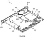
- the cold plate 1 is produced by mechanical assembly of a plurality of elements.
- the cold plate 1 firstly comprises a slender proximal edge 10 which has the function of allowing the entry and exit of the refrigerant fluid from the cold plate 1.
- the proximal edge 10 constitutes the start of the cooling circuit and the end of the evacuation circuit.
- the proximal edge 10 comprises at one of its ends a refrigerant fluid inlet connector 110 and at its other end an outlet connector 120 of refrigerant fluid.
- the inlet connector 110 and the outlet connector 120 are mounted on the proximal edge 10 using screws 100.
- the inlet connector 110 and the outlet connector 120 are each configured to receive a tube, for example flexible, making it possible to connect the cold plate 1 to the refrigerant cooling module, in particular when the cold plate 1 is mounted in the blade Calculation.
- the proximal edge 10 is mounted on a substantially rectangular central part 20 making it possible to convey the fluid to the heat sinks.
- the proximal edge 10 and the central piece 20 are assembled using screws 100.
- the cold plate 1 then comprises a distal edge 30 connected to the central part 20 by a first connecting member 40 and by a second connecting member 50.
- the distal edge 30 includes part of the evacuation circuit.
- the central piece 20, the distal edge 30, the first connecting member 40 and the second connecting member 50 delimit a first opening O1 intended to receive a heat sink (not shown for the sake of clarity) which is configured to connect on the one hand to the cooling circuit at the central part 20 to receive the cold refrigerant fluid and on the other hand to the evacuation circuit of the distal edge 30 to evacuate the heated refrigerant fluid towards the outlet connector 120.
- a heat sink not shown for the sake of clarity
- the cold plate 1 In order to convey the heated refrigerating fluid from the distal edge 30 to the proximal edge 10, the cold plate 1 comprises a fluid junction member 60 mounted between the proximal edge 10 and the distal edge 30.
- the fluid junction member 60 fluid junction 60 is part of the evacuation circuit and makes it possible to convey the heated refrigerant fluid from the distal edge 30 to the proximal edge 10 which then leads it to the outlet connector 120.
- the proximal edge 10, the central piece 20, the distal edge 30, the first connecting member 40 and the junction member 60 delimit a second opening O2 intended to receive two pairs of heat sinks (not shown for the sake of clarity) which are each configured to connect on the one hand to the cooling circuit at the level of the central part 20 to receive the cold refrigerant fluid and on the other hand to the evacuation circuit of the distal edge 30 and to the junction member 60 to evacuate the heated refrigerant fluid towards the outlet connector 120.
- two pairs of heat sinks (not shown for the sake of clarity) which are each configured to connect on the one hand to the cooling circuit at the level of the central part 20 to receive the cold refrigerant fluid and on the other hand to the evacuation circuit of the distal edge 30 and to the junction member 60 to evacuate the heated refrigerant fluid towards the outlet connector 120.
- sealing members are used at the level of the fluid connections between the different elements.
- the sealing members are in the form of O-rings 200 placed at the interface of each fluid connection between two elements.
- O-rings 200 placed at the level of the fluidic connections between the proximal edge 10 and the central part 20 and the O-ring placed between the inlet connector 110 and the proximal edge 10 have been shown for the sake of clarity but it goes without saying so that all of the fluid connections between the elements of the cold plate 1 are provided with such O-rings 200 to ensure the sealing of the refrigerant circulation circuit in said cold plate 1.
- the O-ring 200 is placed in a groove formed, in this non-limiting example, in the central part 20 so as to be in compression controlled around the fluid connection between the proximal edge 10 and the central part 20.
- the flow F of refrigerant fluid can travel from the proximal edge 10 to the central part 20 without loss.
- sealing members in particular of the O-ring 200 type, can be used where necessary at the interface of the fluid connections in the refrigerant circulation circuit (cooling circuit and evacuation circuit ).
- positioning members are used in order to facilitate the assembly of the elements and guarantee the correct alignment of the orifices 250 of the evacuation circuit.
- These positioning members include in particular indexing pins 310 adapted to be housed in complementary blocking cavities 320, preferably with tight tolerances (ie less than or of the order of a millimeter).
- the junction member 60 comprises two indexing pins 310, arranged symmetrically on either side of the fluid connection of the evacuation circuit and the proximal edge 10 comprises two blocking cavities 320.
- FIG 4 also illustrates the orifices for receiving the screws 100 both at the proximal edge 10 (orifices 12) and at the junction member (orifices 62).
- O-rings 200 are placed around the fluid junctions of the refrigerant circulation circuit of the cold plate 1 at the interface of the elements of the cold plate 1 concerned by said circulation circuit.
- the elements are assembled two by two by tightening the screws 100 in the corresponding holes 12, 62 in a step E2.
- the O-rings 200 are compressed in controlled compression to the stop of the elements of the cold plate 1 so as to guarantee the tightness of the fluid connections.
- the cold plate 1 according to the invention allows, thanks to an assembly of elements, adaptability to any type and shape of heat sink while saving the volume of material of the openings which was otherwise machined and therefore eliminated.
- the sealing members make it possible to guarantee the tightness of the refrigerant circulation circuit and thus the efficiency of the cold plate 1.
Landscapes
- Engineering & Computer Science (AREA)
- Microelectronics & Electronic Packaging (AREA)
- Physics & Mathematics (AREA)
- Thermal Sciences (AREA)
- General Engineering & Computer Science (AREA)
- Computer Hardware Design (AREA)
- Theoretical Computer Science (AREA)
- Human Computer Interaction (AREA)
- General Physics & Mathematics (AREA)
- Aviation & Aerospace Engineering (AREA)
- Cooling Or The Like Of Electrical Apparatus (AREA)
- Cooling Or The Like Of Semiconductors Or Solid State Devices (AREA)
Priority Applications (2)
| Application Number | Priority Date | Filing Date | Title |
|---|---|---|---|
| EP22306440.3A EP4345578A1 (de) | 2022-09-28 | 2022-09-28 | Zusammengesetzte kühlplatte für berechnungsklinge |
| US18/469,950 US20240107705A1 (en) | 2022-09-28 | 2023-09-19 | Assembled cold plate for compute blade |
Applications Claiming Priority (1)
| Application Number | Priority Date | Filing Date | Title |
|---|---|---|---|
| EP22306440.3A EP4345578A1 (de) | 2022-09-28 | 2022-09-28 | Zusammengesetzte kühlplatte für berechnungsklinge |
Publications (1)
| Publication Number | Publication Date |
|---|---|
| EP4345578A1 true EP4345578A1 (de) | 2024-04-03 |
Family
ID=84604226
Family Applications (1)
| Application Number | Title | Priority Date | Filing Date |
|---|---|---|---|
| EP22306440.3A Pending EP4345578A1 (de) | 2022-09-28 | 2022-09-28 | Zusammengesetzte kühlplatte für berechnungsklinge |
Country Status (2)
| Country | Link |
|---|---|
| US (1) | US20240107705A1 (de) |
| EP (1) | EP4345578A1 (de) |
Citations (2)
| Publication number | Priority date | Publication date | Assignee | Title |
|---|---|---|---|---|
| US20150075755A1 (en) * | 2013-04-15 | 2015-03-19 | International Business Machines Corporation | Fabricating separable and integrated heat sinks facilitating cooling multi-component electronic assembly |
| US20150109729A1 (en) * | 2013-10-21 | 2015-04-23 | International Business Machines Corporation | Field-replaceable bank of immersion-cooled electronic components and separable heat sinks |
Family Cites Families (6)
| Publication number | Priority date | Publication date | Assignee | Title |
|---|---|---|---|---|
| US4498119A (en) * | 1980-11-03 | 1985-02-05 | Lockheed Corporation | Electronic circuit board and method and apparatus for thermal management thereof |
| US7515418B2 (en) * | 2005-09-26 | 2009-04-07 | Curtiss-Wright Controls, Inc. | Adjustable height liquid cooler in liquid flow through plate |
| US9497888B2 (en) * | 2013-02-27 | 2016-11-15 | International Business Machines Corporation | Thermal transfer structure(s) and attachment mechanism(s) facilitating cooling of electronics card(s) |
| US9943016B2 (en) * | 2014-11-04 | 2018-04-10 | Ge Aviation Systems Llc | Cooling structure |
| JP6717080B2 (ja) * | 2016-06-30 | 2020-07-01 | 富士通株式会社 | 情報処理装置、及び冷却ユニット |
| TWI784614B (zh) * | 2021-07-07 | 2022-11-21 | 訊凱國際股份有限公司 | 伺服裝置與承載殼體 |
-
2022
- 2022-09-28 EP EP22306440.3A patent/EP4345578A1/de active Pending
-
2023
- 2023-09-19 US US18/469,950 patent/US20240107705A1/en active Pending
Patent Citations (2)
| Publication number | Priority date | Publication date | Assignee | Title |
|---|---|---|---|---|
| US20150075755A1 (en) * | 2013-04-15 | 2015-03-19 | International Business Machines Corporation | Fabricating separable and integrated heat sinks facilitating cooling multi-component electronic assembly |
| US20150109729A1 (en) * | 2013-10-21 | 2015-04-23 | International Business Machines Corporation | Field-replaceable bank of immersion-cooled electronic components and separable heat sinks |
Also Published As
| Publication number | Publication date |
|---|---|
| US20240107705A1 (en) | 2024-03-28 |
Similar Documents
| Publication | Publication Date | Title |
|---|---|---|
| EP2421350B1 (de) | Elektrogerät zur Fluidabkühlung, Ausbuchtung im Luftfahrzeug zur Aufnahme eines solchen Geräts und mit solchen Ausbuchtungen ausgestattetes Luftfahrzeug | |
| FR2580433A1 (fr) | Connecteur thermique pour carte de circuit imprime revetue de composants electroniques | |
| EP3500079A1 (de) | Flüssiges kühlsystem für elektronische karte, die aus einer kälteplatte und kühlkörpern besteht, die über flexible verbindungen mit dieser kälteplatte verbunden sind | |
| EP2628371A1 (de) | Kühlkörper für ein an eine computerplatine anschliessbares auswechselbares expansionsmodul | |
| FR3002624A1 (fr) | Repartiteur hydraulique | |
| FR2850158A1 (fr) | Systeme modulaire de chauffage ou de refroidissement | |
| WO2009062944A1 (fr) | Dispositif de refroidissement d'un fluide caloporteur | |
| EP4345578A1 (de) | Zusammengesetzte kühlplatte für berechnungsklinge | |
| EP4345575B1 (de) | Verfahren zur herstellung eines kühlkörpers | |
| EP4345577A1 (de) | Kühlkörper für eine berechnungsblatt-array-karte | |
| EP1917441B1 (de) | Pumpengehäuse | |
| EP4332728B1 (de) | Computerblade mit versetzten netzwerkkarten | |
| EP4333577B1 (de) | Zwischenkühlkörper für ein kühlsystem einer elektronischen superrechnerkarte | |
| EP4333575B1 (de) | Eingangskühlkörper für ein kühlsystem einer elektronischen superrechnerkarte | |
| WO2023213609A1 (fr) | Ensemble pour réservoir dessiccateur au sein d'un circuit de gestion thermique | |
| WO2020201011A1 (fr) | Interface et ensemble de raccordement de tubulures de fluide réfrigérant dans un ensemble de refroidissement d'un dispositif de stockage électrique | |
| EP4333576B1 (de) | Ausgangskühlkörper für ein kühlsystem einer elektronischen superrechnerkarte | |
| FR3158309A1 (fr) | Ensemble thermique pour un système de propulsion d’un aéronef | |
| FR2920946A1 (fr) | Dispositif permettant d'evacuer la chaleur produite par des composants fixes sur des cartes enfichables disposees dans un boitier | |
| EP0091335A1 (de) | Thermisches Verbindungssystem | |
| FR3034184A1 (fr) | Boite collectrice pour echangeur thermique a faisceau de tubes | |
| WO2026021948A1 (fr) | Dispositif de refroidissement | |
| EP4345576A1 (de) | Kühlkörper für aktiven verbinder eines berechnungsblatts | |
| WO2025223835A1 (fr) | Dispositif de régulation thermique, et système comprenant un dispositif de régulation thermique | |
| FR3167032A1 (fr) | Boîtier étanche configuré pour recevoir un ou plusieurs composants |
Legal Events
| Date | Code | Title | Description |
|---|---|---|---|
| PUAI | Public reference made under article 153(3) epc to a published international application that has entered the european phase |
Free format text: ORIGINAL CODE: 0009012 |
|
| STAA | Information on the status of an ep patent application or granted ep patent |
Free format text: STATUS: THE APPLICATION HAS BEEN PUBLISHED |
|
| STAA | Information on the status of an ep patent application or granted ep patent |
Free format text: STATUS: REQUEST FOR EXAMINATION WAS MADE |
|
| AK | Designated contracting states |
Kind code of ref document: A1 Designated state(s): AL AT BE BG CH CY CZ DE DK EE ES FI FR GB GR HR HU IE IS IT LI LT LU LV MC MK MT NL NO PL PT RO RS SE SI SK SM TR |
|
| 17P | Request for examination filed |
Effective date: 20240318 |
|
| RBV | Designated contracting states (corrected) |
Designated state(s): AL AT BE BG CH CY CZ DE DK EE ES FI FR GB GR HR HU IE IS IT LI LT LU LV MC MK MT NL NO PL PT RO RS SE SI SK SM TR |
|
| RAP1 | Party data changed (applicant data changed or rights of an application transferred) |
Owner name: LE COMMISSARIAT A L'ENERGIE ATOMIQUE ET AUX ENERGIES ALTERNATIVES Owner name: BULL SAS |
|
| RAP3 | Party data changed (applicant data changed or rights of an application transferred) |
Owner name: COMMISSARIAT A L'ENERGIE ATOMIQUE ET AUX ENERGIESALTERNATIVES Owner name: BULL SAS |
|
| P01 | Opt-out of the competence of the unified patent court (upc) registered |
Free format text: CASE NUMBER: APP_22895/2025 Effective date: 20250514 |
|
| STAA | Information on the status of an ep patent application or granted ep patent |
Free format text: STATUS: EXAMINATION IS IN PROGRESS |
|
| 17Q | First examination report despatched |
Effective date: 20251202 |