EP4334210B1 - Verbessertes getriebe für hybridflugzeuge - Google Patents
Verbessertes getriebe für hybridflugzeuge Download PDFInfo
- Publication number
- EP4334210B1 EP4334210B1 EP22735524.5A EP22735524A EP4334210B1 EP 4334210 B1 EP4334210 B1 EP 4334210B1 EP 22735524 A EP22735524 A EP 22735524A EP 4334210 B1 EP4334210 B1 EP 4334210B1
- Authority
- EP
- European Patent Office
- Prior art keywords
- electric machine
- main rotor
- gas generator
- turbomachine
- free turbine
- Prior art date
- Legal status (The legal status is an assumption and is not a legal conclusion. Google has not performed a legal analysis and makes no representation as to the accuracy of the status listed.)
- Active
Links
Images


Classifications
-
- B—PERFORMING OPERATIONS; TRANSPORTING
- B64—AIRCRAFT; AVIATION; COSMONAUTICS
- B64D—EQUIPMENT FOR FITTING IN OR TO AIRCRAFT; FLIGHT SUITS; PARACHUTES; ARRANGEMENT OR MOUNTING OF POWER PLANTS OR PROPULSION TRANSMISSIONS IN AIRCRAFT
- B64D27/00—Arrangement or mounting of power plants in aircraft; Aircraft characterised by the type or position of power plants
- B64D27/02—Aircraft characterised by the type or position of power plants
- B64D27/10—Aircraft characterised by the type or position of power plants of gas-turbine type
-
- B—PERFORMING OPERATIONS; TRANSPORTING
- B64—AIRCRAFT; AVIATION; COSMONAUTICS
- B64D—EQUIPMENT FOR FITTING IN OR TO AIRCRAFT; FLIGHT SUITS; PARACHUTES; ARRANGEMENT OR MOUNTING OF POWER PLANTS OR PROPULSION TRANSMISSIONS IN AIRCRAFT
- B64D35/00—Transmitting power from power plants to propellers or rotors; Arrangements of transmissions
- B64D35/02—Transmitting power from power plants to propellers or rotors; Arrangements of transmissions specially adapted for specific power plants
- B64D35/021—Transmitting power from power plants to propellers or rotors; Arrangements of transmissions specially adapted for specific power plants for electric power plants
- B64D35/022—Transmitting power from power plants to propellers or rotors; Arrangements of transmissions specially adapted for specific power plants for electric power plants of hybrid-electric type
- B64D35/023—Transmitting power from power plants to propellers or rotors; Arrangements of transmissions specially adapted for specific power plants for electric power plants of hybrid-electric type of series-parallel type
-
- B—PERFORMING OPERATIONS; TRANSPORTING
- B64—AIRCRAFT; AVIATION; COSMONAUTICS
- B64D—EQUIPMENT FOR FITTING IN OR TO AIRCRAFT; FLIGHT SUITS; PARACHUTES; ARRANGEMENT OR MOUNTING OF POWER PLANTS OR PROPULSION TRANSMISSIONS IN AIRCRAFT
- B64D35/00—Transmitting power from power plants to propellers or rotors; Arrangements of transmissions
- B64D35/02—Transmitting power from power plants to propellers or rotors; Arrangements of transmissions specially adapted for specific power plants
- B64D35/021—Transmitting power from power plants to propellers or rotors; Arrangements of transmissions specially adapted for specific power plants for electric power plants
- B64D35/022—Transmitting power from power plants to propellers or rotors; Arrangements of transmissions specially adapted for specific power plants for electric power plants of hybrid-electric type
- B64D35/024—Transmitting power from power plants to propellers or rotors; Arrangements of transmissions specially adapted for specific power plants for electric power plants of hybrid-electric type of series type
-
- F—MECHANICAL ENGINEERING; LIGHTING; HEATING; WEAPONS; BLASTING
- F01—MACHINES OR ENGINES IN GENERAL; ENGINE PLANTS IN GENERAL; STEAM ENGINES
- F01D—NON-POSITIVE DISPLACEMENT MACHINES OR ENGINES, e.g. STEAM TURBINES
- F01D15/00—Adaptations of machines or engines for special use; Combinations of engines with devices driven thereby
- F01D15/10—Adaptations for driving, or combinations with, electric generators
-
- F—MECHANICAL ENGINEERING; LIGHTING; HEATING; WEAPONS; BLASTING
- F02—COMBUSTION ENGINES; HOT-GAS OR COMBUSTION-PRODUCT ENGINE PLANTS
- F02C—GAS-TURBINE PLANTS; AIR INTAKES FOR JET-PROPULSION PLANTS; CONTROLLING FUEL SUPPLY IN AIR-BREATHING JET-PROPULSION PLANTS
- F02C3/00—Gas-turbine plants characterised by the use of combustion products as the working fluid
- F02C3/04—Gas-turbine plants characterised by the use of combustion products as the working fluid having a turbine driving a compressor
- F02C3/10—Gas-turbine plants characterised by the use of combustion products as the working fluid having a turbine driving a compressor with another turbine driving an output shaft but not driving the compressor
-
- F—MECHANICAL ENGINEERING; LIGHTING; HEATING; WEAPONS; BLASTING
- F02—COMBUSTION ENGINES; HOT-GAS OR COMBUSTION-PRODUCT ENGINE PLANTS
- F02C—GAS-TURBINE PLANTS; AIR INTAKES FOR JET-PROPULSION PLANTS; CONTROLLING FUEL SUPPLY IN AIR-BREATHING JET-PROPULSION PLANTS
- F02C7/00—Features, components parts, details or accessories, not provided for in, or of interest apart form groups F02C1/00 - F02C6/00; Air intakes for jet-propulsion plants
- F02C7/32—Arrangement, mounting, or driving, of auxiliaries
-
- B—PERFORMING OPERATIONS; TRANSPORTING
- B64—AIRCRAFT; AVIATION; COSMONAUTICS
- B64C—AEROPLANES; HELICOPTERS
- B64C27/00—Rotorcraft; Rotors peculiar thereto
- B64C27/04—Helicopters
- B64C27/12—Rotor drives
-
- F—MECHANICAL ENGINEERING; LIGHTING; HEATING; WEAPONS; BLASTING
- F05—INDEXING SCHEMES RELATING TO ENGINES OR PUMPS IN VARIOUS SUBCLASSES OF CLASSES F01-F04
- F05B—INDEXING SCHEME RELATING TO WIND, SPRING, WEIGHT, INERTIA OR LIKE MOTORS, TO MACHINES OR ENGINES FOR LIQUIDS COVERED BY SUBCLASSES F03B, F03D AND F03G
- F05B2220/00—Application
- F05B2220/50—Application for auxiliary power units (APU's)
-
- F—MECHANICAL ENGINEERING; LIGHTING; HEATING; WEAPONS; BLASTING
- F05—INDEXING SCHEMES RELATING TO ENGINES OR PUMPS IN VARIOUS SUBCLASSES OF CLASSES F01-F04
- F05D—INDEXING SCHEME FOR ASPECTS RELATING TO NON-POSITIVE-DISPLACEMENT MACHINES OR ENGINES, GAS-TURBINES OR JET-PROPULSION PLANTS
- F05D2220/00—Application
- F05D2220/50—Application for auxiliary power units (APU's)
-
- F—MECHANICAL ENGINEERING; LIGHTING; HEATING; WEAPONS; BLASTING
- F05—INDEXING SCHEMES RELATING TO ENGINES OR PUMPS IN VARIOUS SUBCLASSES OF CLASSES F01-F04
- F05D—INDEXING SCHEME FOR ASPECTS RELATING TO NON-POSITIVE-DISPLACEMENT MACHINES OR ENGINES, GAS-TURBINES OR JET-PROPULSION PLANTS
- F05D2220/00—Application
- F05D2220/70—Application in combination with
- F05D2220/76—Application in combination with an electrical generator
Definitions
- the present invention relates to the field of hybrid aircraft, comprising at least one turbomachine such as a turboshaft or a turboprop, for flying machines such as helicopters or airplanes.
- the invention relates to a transmission device for a hybrid aircraft, and a hybrid aircraft comprising such a transmission device.
- a turbomachine for example a turboshaft engine, in particular for a helicopter, comprises a gas turbine having a gas generator and a free turbine driven in rotation by the gas flow generated by the gas generator.
- a hybrid aircraft generally comprises, in addition to this turbomachine, a reversible electrical machine coupled to the gas generator, so as to rotate the gas generator during a start-up phase of the turbomachine, or in flight so as to provide the non-propulsion electrical needs of the aircraft.
- the gas generator comprises at least one compressor and one turbine coupled in rotation.
- the operating principle is as follows: the fresh air entering the gas turbine is compressed due to the rotation of the compressor before being sent to a combustion chamber where it is mixed with a fuel. The burnt gases due to the combustion are then evacuated at high speed. An initial expansion then occurs in the gas generator turbine, during which the latter extracts the energy necessary to drive the compressor.
- the gas generator turbine does not absorb all the kinetic energy of the burnt gases and the excess kinetic energy corresponds to the gas flow generated by the gas generator. The latter therefore provides kinetic energy to the free turbine so that a second expansion occurs in the free turbine which transforms this kinetic energy into mechanical energy in order to drive a receiving organ, such as the rotor of the helicopter.
- Improving the power density and reliability of the electrical chain equipment now makes it possible to consider hybridizing the main rotor, i.e. having at least one electrical machine connected to the main rotor and capable of providing it with power.
- This power complementary to the power of the turbine, allows in particular a power supply for transient phases (resources, take-off, etc.), a power supply to relieve the gas turbine and optimize its service life, and also 100% electric operation in the event of loss of the gas turbine, for a limited period.
- this electrical machine it is possible to use this electrical machine to generate electricity (for current consumption and/or to recharge batteries).
- the electrical machine(s) must be sized to a power much higher than that of the generators/starters usually used, typically one or several hundred kilowatts, instead of around ten kilowatts. It is therefore desirable to pool the two types of electrical machines (the turbine generator/starter and the electrical machine connected to the rotor).
- the proposed architectures do not allow certain functions to be performed by the electric machines.
- these architectures only allow the electric machine to supply power to the gas generator during start-up. It is also not possible to continuously draw power from the helicopter rotor with an electric machine and continuously reinject this power into the gas generator with another electric machine. More specifically, assistance to the gas generator in flight is only possible by activating at least one lockable freewheel or clutch each time it is used.
- a lockable freewheel or clutch system is likely to be used frequently, and is associated with high criticality. In other words, given the frequent use of the functions with which these engageable elements are associated, the risks of malfunction are significant, limiting the reliability of the device.
- such architectures do not ensure an optimal level of redundancy, and also involve a high number of components and connections.
- the architectures proposed in this document do not allow addressing certain functionalities specific to helicopter applications in which the main rotor and the free turbine may be desynchronized.
- assistance with autorotation by electric machines by injecting power into the transmission, or electrical generation to power the on-board systems, downstream of the engine freewheel is not permitted, in particular following a failure of the turbomachine.
- the present disclosure relates to a turbomachine for a hybrid aircraft, in particular a helicopter, the turbomachine comprising at least one gas generator, a free turbine driven in rotation by a gas flow generated by the gas generator, a main rotor, and a transmission device comprising a first reversible electric machine capable of being coupled to a shaft of the free turbine via a first deactivatable coupling means, and to the main rotor, and a second reversible electric machine capable of being coupled to a shaft of the gas generator via a second deactivatable coupling means, and of being coupled to the main rotor via a third deactivatable coupling means, the second deactivatable coupling means being configured to be activated when the second electric machine rotates in a first direction of rotation, and the third deactivatable coupling means being configured to be activated when the second electric machine rotates in a second direction of rotation opposite to the first direction of rotation.
- deactivatable coupling means that the coupling means can be in an activated position in which the members connected to said coupling means are coupled, or in a deactivated position in which said members are decoupled, it being understood that by “member” is meant the electrical machines, the main rotor, the gas generator and the free turbine.
- the drive device is particularly advantageous in that the two electrical machines are specialized in order to provide complementary functions, while together ensuring the level of redundancy necessary on the critical functions to increase the safety of the flight.
- the first electric machine can provide the tapping on the free turbine or the main rotor, so as not to affect the performance of the gas generator, or the injection of power on the main rotor so as to assist the latter in certain operating phases.
- the second electric machine can be used in one direction of rotation to be mechanically coupled to the gas generator, and in the other direction of rotation to be mechanically coupled to the main rotor.
- the second electric machine rotating in the first direction of rotation allows the coupling with the gas generator in order to start the latter on the ground, but also the coupling with the gas generator in order to supplement the thermodynamic power in certain flight phases, for assistance with transient phases or modification of the engine operating point for example.
- the second electrical machine rotating in the first direction of rotation makes it possible to restart the gas generator in flight, for example following a failure thereof, without requiring the activation of another mechanical member such as a clutch. Furthermore, even when the second electrical machine is used in the first direction of rotation to restart the electrical generator in flight, the first electrical machine can be used in parallel to drive the main rotor.
- the second electric machine rotating in the second direction of rotation makes it possible to drive the main rotor as a replacement for the first electric machine in the event of a failure of the latter, or as a supplement to the latter in certain flight phases requiring an additional supply of power.
- the architecture according to the present disclosure has the advantage of being simple by limiting the number of components and connections, while ensuring a good level of redundancy and making it possible to perform a high number of functions, and thus to improve the reliability of the device.
- the second reversible electrical machine makes it possible to both start or assist the gas generator or the main rotor.
- a single active system also makes it possible to supply electricity by drawing from the gas generator for the recharging the batteries on the ground, or in the event of failure of the first electric machine for example.
- the first, second, and third deactivatable coupling means comprise a freewheel.
- the freewheel does not need to be controlled electronically or mechanically by an external operator.
- the freewheel also has significant reliability.
- Such a freewheel is generally made up of a hub and a peripheral crown rotatably mounted on the hub.
- the hub can generally drive the peripheral crown in rotation but not vice versa.
- the freewheel is arranged such that the peripheral crown can drive the hub in rotation, but not vice versa, without compromising the principle of the present invention.
- the hub can only drive the crown when the hub rotates in a predetermined direction relative to the crown, which will be called the "direction of engagement". Otherwise, the hub and the peripheral crown rotate freely relative to each other.
- the deactivatable coupling means are activated when the hub of the freewheel rotates the peripheral ring gear, and, conversely, the deactivatable coupling means are deactivated when the hub of the freewheel does not rotate the peripheral ring gear.
- the first electrical machine is configured to operate in generator mode, in which it is rotated by transmission members and the main rotor, which can themselves be driven by the free turbine via the first coupling means, so as to generate electrical energy, or in motor mode in which it supplies power to the main rotor.
- the first electric machine can thus generate electrical energy without drawing power from the gas generator, which improves the specific consumption of the gas turbine.
- the device transmission of the present disclosure allows a simultaneous supply of electrical power to the main rotor by the first electric machine, and to the gas generator by the second electric machine.
- the device comprises a rotor brake capable of being arranged between the free turbine and the main rotor while being movable between a braking position preventing the main rotor from being driven by the free turbine, and a free position allowing the main rotor to be driven by the free turbine.
- the first electrical machine and the free turbine are coupled to the main rotor, while a mobile rotor brake arranged on the kinematic chain allows it to be blocked.
- the hot gases drive the free turbine.
- the latter connected to the main rotor via the first coupling means, can be either free when the rotor brake is in the free position, or blocked by the rotor brake when the latter is in the braking position. This braking position therefore allows the free turbine, and therefore the main rotor, to be blocked, in particular in the event of start-up in strong winds.
- the first electric machine is configured to rotate in a direction opposite to the direction of rotation of the main rotor, so as to brake the drive of the main rotor by the free turbine.
- the first electric machine is configured to generate a resistive torque, making it possible to counteract the torque of the free turbine driving the main rotor.
- the first electric machine can thus fulfill the functions of the rotor brake described in the preceding paragraph, without requiring the use of the latter.
- This alternative is advantageous insofar as a rotor brake, which is an expensive element, must be regularly checked and changed. It also presents a risk of unwanted activation in flight. This alternative therefore makes it possible to limit costs and improve the reliability of the device.
- the device comprises a dog clutch, or a clutch disposed between the rotor brake and the free turbine, the dog clutch being movable between a coupling position in which the shaft of the free turbine is coupled with the main rotor, and a decoupling position in which the shaft of the free turbine and the main rotor are decoupled, the first machine electric being coupled to the free turbine upstream of the dog clutch, so that the free turbine can supply electrical power to the first electric machine even when the dog clutch is in the decoupled position.
- upstream refers to the direction of flow of mechanical energy towards the main rotor, in other words, the "free turbine - main rotor” direction.
- it is necessary to be able to generate electrical power while keeping the rotor locked. Switching the dog clutch to the decoupling position thus allows the use of the rotor brake, while keeping the free turbine on to generate electrical power on the first electrical machine, without damaging the free turbine.
- the first electrical machine is electrically connected to the second electrical machine, such that the device is capable of transferring electrical power from the main rotor to the gas generator via the first electrical machine and the second electrical machine rotating in the first direction of rotation.
- the first electrical machine connected to the main rotor and the free turbine draws power, transmitted in the form of electric current to the second electrical machine which restores it to the gas generator via the second coupling means, rotating in the first direction of rotation.
- Exchanging electrical power between the gas generator and the main rotor makes it possible to modify the operating point of the turbine to increase the net power seen by the main rotor at iso service life of the gas turbine or to increase the service life of the gas turbine at iso net power seen by the main rotor of the helicopter.
- the second coupling means comprises a locking means movable between a free position in which the gas generator cannot rotate the second electrical machine, and a locked position in which the gas generator is able to rotate the second electrical machine, so that the second electric machine draws electrical power from the gas generator.
- the device is configured such that electrical power drawn from the gas generator by the second electrical machine is transferred to the first electrical machine.
- the locking means is a means for forcing the coupling between the second electrical machine and the gas generator.
- the coupling means comprises a freewheel and a locking means
- the freewheel is called a "lockable freewheel", such that in the locked position, the hub of the freewheel can rotate the peripheral ring of the lockable freewheel.
- the gas generator is capable of rotating the second electrical machine.
- the second electrical machine can be used to draw power from the GG and thus provide electrical power to the onboard network in APU (Auxilary Power Unit) mode on the ground for recharging the batteries for example, or in flight in addition to or as a replacement for the first electrical machine in the event of its failure for example.
- APU Advanced Power Unit
- the electrical power thus generated on the second electrical machine can be used by the first electrical machine, via an electrical connection between the first electrical machine and the second electrical machine.
- the device includes a control unit configured to control the first electric machine, the second electric machine, the locking means, the rotor brake, and the dog clutch.
- hybrid aircraft in particular a helicopter, comprising a turbomachine having at least one gas generator, a free turbine driven in rotation by a gas flow generated by the gas generator, a main rotor, and comprising a transmission device according to any one of the preceding embodiments.
- hybrid aircraft means an aircraft comprising a heat engine allowing to drive a main rotor in rotation, and at least one electric machine to provide power to the heat engine.
- the hybrid aircraft is a helicopter.
- a first embodiment of the invention corresponding to a first architecture of the transmission device 1, will be described in the remainder of the description, with reference to: Figures 1 to 9 .
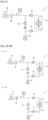
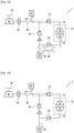
- FIG 1 schematically represents a turbomachine 100 in accordance with the present disclosure, intended in particular to drive in rotation transmission members 50 of a helicopter carrying a propeller or a main rotor 52.
- the turbomachine 100 comprises a gas turbine 10 having a gas generator 12 and a free turbine 14 capable of being driven in rotation by a gas flow generated by the gas generator 12.
- the free turbine 14 is mounted on a shaft 16 which transmits the rotational movement to a receiving member such as a main rotor 52 of the helicopter via the transmission members 50.
- the gas turbine 10 shown in the figure 1 is of the front power take-off type with coaxial shaft return.
- a free turbine gas turbine of the front power take-off type with coaxial shaft return internal or external shaft, or a free turbine turbomachine of the rear power take-off type.
- the gas generator 12 comprises a rotating shaft 18 on which are mounted a compressor 20 and a turbine 22, as well as a combustion chamber 24 arranged axially between the compressor 20 and the turbine when the gas generator 12 is considered in the axial direction of the rotating shaft 18.
- the gas turbine 10 has a casing 26 provided with an air inlet 28 through which the fresh air enters the gas generator 12. After its admission into the enclosure of the gas generator 12, the fresh air is compressed by the compressor 20 which delivers it towards the inlet of the combustion chamber 24 in which it is mixed with fuel.
- the combustion taking place in the combustion chamber 24 causes the burnt gases to be evacuated at high speed towards the turbine 22, which has the effect of driving the shaft 18 of the gas generator 12 and, consequently, the compressor 20 into rotation.
- the speed of rotation of the shaft 18 of the gas generator 12 is determined by the flow rate of fuel entering the combustion chamber 24.
- the gas flow exiting the gas generator has significant kinetic energy.
- the gas flow F is directed towards the free turbine 14 which has the effect of causing an expansion in the free turbine 14 leading to the rotation of the turbine wheel and the shaft 16.
- a transmission device 1 comprises a first reversible electric machine 30 consisting in this case of an electric motor capable of operating reversibly as an electric generator. It will be noted that although the first reversible electric machine 30 can be arranged in the turbomachine perimeter, this arrangement is not limiting. The reversible electric machine 30 can in fact be arranged in perimeters of the helicopter distinct from the turbomachine 100, without departing from the scope of the invention. This remark applies generally to the entire transmission device also comprising the second electric machine and the various coupling means described in the remainder of the description.
- the first reversible electric machine 30 is mechanically coupled to the shaft 16 of the free turbine 14 via a first deactivatable coupling means 32.
- the first deactivatable coupling means 32 comprises a freewheel mounted such that rotation of the shaft 16 can rotate the main rotor 52 and a shaft 38 of the first electrical machine 30 when the latter is operating in generator mode in order to provide electricity, but that, on the contrary, rotation of the shaft 38 of the first electrical machine 30 cannot rotate the shaft 16 of the free turbine 14.
- the freewheel of the first coupling means 32 can only transfer a rotational torque in the direction of the free turbine 14 to the main rotor 52 and the first electrical machine 30, but not vice versa. On a helicopter, this freewheel is commonly called a "motor freewheel". It will be noted that the use of a freewheel for the deactivatable coupling means is not limiting, the freewheel being able to be replaced by any dog or clutch system.
- the first electric machine 30 is also capable of being coupled to the main rotor 52 in such a way that the first electric machine 30, operating in electric motor mode, is capable of rotating the main rotor 52. As indicated above, the first electric machine 30 in electric motor mode can rotate the main rotor 52, but not the free turbine 14, given the presence of the freewheel of the first coupling means 32.
- the device preferably comprises a rotor brake 60 arranged between the first electric machine 30 and the main rotor 52.
- the rotor brake 60 is movable between a braking position (represented by a cross on the Figure 3B for example), preventing rotation of the main rotor 52 and the free turbine 14, and a free position allowing rotation of the main rotor 52 and the free turbine 14.
- a braking position represented by a cross on the Figure 3B for example
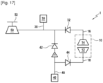
- the rotor brake function can also be fulfilled by the first electric machine 30 which, by being controlled in such a way as to create a torque opposing the rotation of the main rotor 52, makes it possible to brake, or even block this latter.
- the first electric machine 30 which, by being controlled in such a way as to create a torque opposing the rotation of the main rotor 52, makes it possible to brake, or even block this latter.
- Such an alternative embodiment is shown in the figure 17 , and is applicable to all embodiments described in the remainder of the disclosure.
- the transmission device further comprises a second reversible electric machine 40, similar to the first reversible electric machine 30.
- the second reversible electric machine 40 is mechanically coupled to the shaft 18 of the gas generator 12 by means of a second deactivatable coupling means 44.
- the second deactivatable coupling means 44 comprises a freewheel mounted such that rotation of a shaft 48 of the second reversible electric machine 40 can rotate the shaft 18 of the gas generator 12 when the second electric machine is operating in electric motor mode (second coupling means 44 activated), but that, on the contrary, rotation of the shaft 18 of the gas generator 12 cannot rotate the shaft 48 of the second reversible electric machine 40.
- the freewheel of the second coupling means 44 can only transfer a rotational torque in the direction of the second electric machine 40 to the gas generator 12, but not vice versa.
- the second electric machine 40 is also capable of being coupled to the main rotor 52, by means of a third reversible coupling means 42 similar to the first and second coupling means and preferably comprising a freewheel, such that the second electric machine 40, operating in electric motor mode (third coupling means 42 activated), is capable of driving the main rotor 52 in rotation.
- the second electrical machine 40 is capable of rotating in a first direction of rotation in which it is mechanically coupled to the shaft 18 of the gas generator 12, and in a second direction of rotation, opposite the first direction of rotation, in which it is mechanically coupled to the main rotor 52.
- a positive direction will be understood in the remainder of the description, as a direction of rotation of the second electrical machine 40 in which the second coupling means 44 is activated, and a negative direction, as a direction of rotation of the second electrical machine 40 in which the third means coupling 42 is activated.
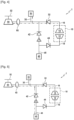
- the element represented by "-1" on the figure 2 and the following figures show gears, for example pinions, allowing the reversal of the direction of rotation.
- the transmission device different functions can be carried out by the transmission device. These different functions are described below with reference to the Figures 3A to 9 .
- the dashed arrows represent a direction of transmission of mechanical or electrical power between two elements.
- mechanical power is transmitted from the second electrical machine 40 to the gas generator 12, and from the free turbine 14 to the main rotor 52.
- the Figures 3A to 16 represent schematically and in a functional and simplified manner the different operating modes of the device, without representing all the details of the elements constituting the turbomachine and the different power transmission organs. In particular, the pinions and possible speed ratios are not represented.
- FIGS. 3A and 3B represent an operating mode allowing the gas turbine 10 to be started.
- the second electrical machine 40 is controlled, for example by a control unit (not shown), so as to rotate in the positive direction.
- a control unit not shown
- the gas generator 12 drives the gas generator 12 via the freewheel of the second coupling means 44, allowing the gas generator 12 to be started.
- the hot gases drive the free turbine 14.
- the latter connected to the main rotor 52 via the freewheel of the first coupling means 32, can be either free, when the rotor brake 60 is in the free position ( Figure 3A ), or blocked by the rotor brake when it is in the braking position ( Figure 3B ).
- This last configuration, illustrated on the Figure 3B can be useful in case of starting in strong wind.
- the power of the second electric machine 40 being of the order of a or several hundred kilowatts, it is possible to start the turbine much more quickly than with a starter with a power of around 10kW, which is usually used. This provides an operational advantage in particular in the case of medical rescue type missions, or during attempts at rapid restart in flight.
- FIG. 4 represents nominal operation, i.e. in flight and in the absence of a breakdown, allowing the first electric machine 30 to operate in electric generator mode.
- the gas generator 12 operates autonomously and is no longer driven by the second electric machine 40.
- the free turbine 14 drives the main rotor 52 and the first electric machine 30 via the freewheel of the first coupling means 32.
- the electrical power generated by the first electric machine 30 can be used to power the on-board electrical accessories or charge the battery.
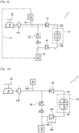
- FIG. 5 represents a nominal operation allowing a power supply to the main rotor 52 by the first electric machine 30 and the second electric machine 40, each operating in electric motor mode.
- the second electric machine 40 then rotates in the negative direction.
- This configuration can be useful in certain phases of flight requiring an additional power supply, for example during takeoff.
- the first electric machine 30 and the second electric machine 40 thus make it possible to supplement the power supplied to the main rotor 52 by the free turbine 14.
- FIG 6 represents a nominal operation allowing the first electric machine 30 to operate in electric generator mode as in the configuration illustrated in the figure 4 , and at the same time enabling a power supply to the gas generator 12 by the second electric machine 40.
- the second electric machine 40 then rotates in the positive direction.
- This configuration may be useful in certain phases of flight, for example for assisting the gas generator during rapid accelerations, or for modifying the engine operating point in “high altitude - hot weather” flight operating conditions.
- FIG 7 represents a nominal operation allowing a power supply to both the main rotor 52 by the first electric machine 30, and to the gas generator 12 by the second electric machine 40, each operating in electric motor mode.
- the second electric machine 40 then rotates in the positive direction. This allows in particular a different strategy from the figure 6 for assistance with rapid transients, in which the electric machine 30 assists the rotor 52 to limit the drop in revolution, while the electric machine 40 assists the gas generator 12 to improve the availability time of the power on the free turbine 14.
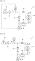
- THE Figures 8A to 8C have an operating mode allowing a restart of the gas turbine 10 in flight, in the event of its stopping.
- the stopping of the gas turbine 10 causes a desynchronization of the free turbine 14 of the main rotor 52 via the freewheel of the first coupling means 32.
- the first electric machine 30 operates in electric motor mode to provide emergency power to the main rotor 52 ( Figure 8A ).
- the speed of the gas generator 12 then decreases to an ignition window, allowing the turbomachine to restart.
- the second electric machine 40 can advantageously be rotated in the positive direction at a speed slightly lower than the re-ignition speed. This saves time and facilitates the resynchronization of the freewheel of the second coupling means 44.
- the electrical machine 40 can contribute to the rapid ramp-up of the gas turbine to reduce the engine power availability time.
- the second electrical machine 40 can otherwise be used to drive the main rotor 52, by rotating in the negative direction, via the third coupling means 42, and thus complete the power supply of the first electric machine 30 ( Figure 8C ) to limit the loss of speed of the rotor 52.
- the free turbine 14 accelerates and thus resynchronizes with the main rotor 52, allowing a return to the nominal situation. Once the nominal situation has been returned, the first and second electrical machines 30, 40 can stop the supply of power to the main rotor 52.
- This architecture is particularly advantageous in that it allows, with only two electric machines, to provide power to the main rotor 52, by the first electric machine 30 and the second electric machine 40, while allowing the restart of the gas turbine 10 by the second electric machine 40 in certain operating phases. It will also be noted that the different steps described above can be carried out by the control unit (not shown), making it possible to detect the stopping of the engine, the rotation speed of the shafts of the gas generator and the free turbine, and to control the electric machines.
- the two electrical machines 30 and 40 (rotating in the negative direction) can provide a power input to the main rotor 52 to assist the autorotation thereof, or even allow a level departure flight before landing.
- This flight phase is functionally equivalent to the configuration illustrated in FIG. Figure 8C .
- the main rotor 52 benefits from all of the available electrical power, provided by the first and second electrical machines 30, 40.
- the remaining electrical machine is capable of providing half of the installed electrical power.
- FIG 9 represents a nominal operation allowing the first electric machine 30 to operate in electric generator mode and allowing at the same time a supply of power to the gas generator 12 by the second electric machine 40, as in the configuration illustrated in the figure 6 .
- the electrical connection 70 may comprise electrical shaping devices (rectification, inverters, voltage conversion). This connection allows the first electric machine 30, connected to the main rotor 52 and to the free turbine 14, to draw electrical power, and to transmit it in the form of electric current via the electrical connection 70 to the second electric machine 40, which then restores it to the gas generator 12, via the second coupling means 44 rotating in the positive direction. It is thus possible to transfer electrical power from the main rotor 52 to the gas generator 12, in certain flight phases requiring such a transfer.
- the second deactivatable coupling means 44 also comprises a blocking means 46.
- the blocking means 46 is movable between a free position in which the gas generator 12 cannot rotate the second electric machine 40, and a blocked position making it possible to block the freewheel of the second deactivatable coupling means 44 and thus to force the coupling between the gas generator 12 and the second electric machine 40.
- the second coupling means 44 acts as a shaft such that the gas generator 12 is able to rotate the second electric machine 40, despite the presence of the freewheel of the second deactivatable coupling means 44.
- the change of position of the blocking means 46 can be carried out by an electrical, pneumatic or hydraulic component and controlled by a user or a control unit.
- the transmission device according to the second embodiment is identical to the transmission device according to the first embodiment described above. Consequently, when the blocking means 46 is in the free position shown schematically in the figure 10 , the functions performed by this second architecture are the same as the functions described above, with reference to the first architecture.
- the Figures 11 to 14 have functions achievable by this second architecture, when the blocking means 46 is in the blocking position.
- FIG 11 has an operation enabling the restarting of the gas turbine 10 to be accelerated in flight, in the event of the latter being stopped.
- the operation of the device in this case, is identical to that described above with reference to the Figures 8A to 8C .
- the blocking means 46 allowing the freewheel of the second coupling means 44 to be blocked, the second electric machine 40 can be used to draw power from the gas generator 12, and thus slow down the rotation speed of the gas generator 12 more quickly, to consequently reach the ignition window more quickly.
- the electrical power thus generated on the second electrical machine 40 can be advantageously used by the first electrical machine 30, via the electrical connection 70 between the first electrical machine 30 and the second electrical machine 40.
- figure 12 has an operation allowing redundant electrical generation on both the first electrical machine 30 and the second electrical machine 40. Indeed, it is sometimes desirable for the helicopter to have two redundant electrical power sources. This is possible by using the second electrical machine 40 as an auxiliary generation source, via the lockable freewheel, more precisely the locking means 46 in the locking position. The use of this function may for example be limited to the case of a failure of the electrical machine 30.
- figure 13 has an operation allowing a transfer of electrical power from the gas generator 12 to the main rotor 52. In this case, the second electrical machine 40 is connected to the gas generator 12 via the freewheel of the second coupling means 44, the freewheel being blocked by the blocking means 46.
- the second electrical machine 40 thus draws power, transmitted in the form of electric current via the electrical connection 70 to the first electric machine 30 which returns it to the main rotor 52. It will be noted that before blocking the freewheel of the second coupling means 44, it is preferable to synchronize the speeds on either side of said freewheel, by controlling the speed of the second electric machine 40 via the control unit for example, by also knowing the speed of the gas generator 12 via the engine regulation system.
- this operating mode called “APU” mode or function (for "Auxiliary Power Unit” in English) is an operating mode where the gas turbine drives an electric generator without driving the main rotor of the helicopter, to provide power to electrical devices on the ground, such as batteries, flight equipment, heating or air conditioning.
- this mode allows the batteries to be recharged which can be used in flight to power the electrical machines to provide electrical assistance to the main rotor 52 from the take-off phase for example.
- the blocking means 46 is in the blocking position so that the gas generator 12 can drive the second electric machine 40.
- the second electric machine 40 thus draws power to restore it to the electrical equipment, while the free turbine 14 is blocked by the rotor brake 60, then in the braking position.
- a third embodiment of the invention corresponding to a third architecture of the transmission device, will be described in the remainder of the description, with reference to the figure 15 .
- the third architecture differs from the second architecture in that the transmission device further comprises a coupling system 80, for example a dog clutch or a clutch.
- the coupling system 80 is movable between a coupling position in which the shaft 16 of the free turbine 14 is coupled with the main rotor 52, and a decoupling position in which the shaft 16 of the free turbine 14 and the main rotor are decoupled.
- upstream and downstream refer to the direction of flow of energy from the free turbine 14 to the main rotor 52, in other words, to the "free turbine - main rotor” direction.
- FIG 15 illustrates a first example of the third architecture, having an operation allowing electricity to be generated on the ground (“APU” mode).
- the blocking means 46 is in the blocking position, and the dog clutch 80 in the decoupling position.
- the gas generator 12 thus drives the second electric machine 40 via the blocked freewheel of the second coupling means 44.
- the second electric machine 40 consequently draws power to restore it to the electrical equipment, while the free turbine 14 can drive the first electric machine 30.
- the dog clutch 80 is arranged downstream of the coupling between the first electric machine 30 and the free turbine 14.
- the presence of the dog clutch 80 at this position allows the use of the rotor brake 60, while allowing the first electric machine 30 to be driven by the free turbine 14 to generate electrical power. Indeed, in certain operational phases on the ground, it is necessary to be able to generate electrical power while keeping the main rotor 52 blocked. However, on certain gas turbines, operation with the free turbine 14 blocked can damage the latter. Decoupling the free turbine 14 from the main rotor 52 by the dog clutch 80 makes it possible to limit this drawback.
- a fourth embodiment of the invention corresponding to a fourth architecture of the transmission device, will be described in the remainder of the description, with reference to the figure 16 .
- the fourth architecture is similar to the first architecture, but differs therefrom in that the transmission device further comprises a dog clutch 80, arranged downstream of the coupling between the first electric machine 30 and the free turbine 14.
- the dog clutch 80 of the fourth architecture may also be identical to the dog clutch 80 of the third architecture.
- the functions performed by the device according to the fourth architecture are identical to those performed by the device according to the first architecture. Furthermore, according to this fourth architecture, when the dog clutch 80 is in the decoupling position, in “APU” mode, electrical generation is only possible by the first electrical machine 30.
Landscapes
- Engineering & Computer Science (AREA)
- Mechanical Engineering (AREA)
- Aviation & Aerospace Engineering (AREA)
- Chemical & Material Sciences (AREA)
- Combustion & Propulsion (AREA)
- General Engineering & Computer Science (AREA)
- Connection Of Motors, Electrical Generators, Mechanical Devices, And The Like (AREA)
- Control Of Eletrric Generators (AREA)
- Arrangement Of Transmissions (AREA)
Claims (10)
- Turbomaschine für ein hybrides Fluggerät, insbesondere einen Hubschrauber, wobei die Turbomaschine mindestens einen Gasgenerator (12), eine freie Turbine (14), die von einem durch den Gasgenerator erzeugten Gasstrom in Drehung versetzt wird, einen Hauptrotor (52) und eine Übertragungsvorrichtung (1) aufweist, die eine erste reversible elektrische Maschine (30) umfasst, die mit einer Welle (16) der freien Turbine (14) über ein erstes deaktivierbares Kopplungsmittel (32) und mit dem Hauptrotor (52) gekoppelt ist, und eine zweite reversible elektrische Maschine (40), die mit einer Welle (18) des Gasgenerators (12) über ein zweites deaktivierbares Kopplungsmittel (44) gekoppelt ist und mit dem Hauptrotor (52) über ein drittes deaktivierbares Kopplungsmittel (42) gekoppelt ist, wobei die Turbomaschine dadurch gekennzeichnet ist, dass das zweite deaktivierbare Kopplungsmittel (44) so ausgelegt ist, dass es aktiviert wird, wenn sich die zweite elektrische Maschine (40) in einer ersten Drehrichtung dreht, und das dritte deaktivierbare Kopplungsmittel (42) so ausgelegt ist, dass es aktiviert wird, wenn sich die zweite elektrische Maschine (40) in einer zweiten Drehrichtung dreht, die der ersten Drehrichtung entgegengesetzt ist.
- Turbomaschine nach Anspruch 1, wobei das erste, zweite und dritte deaktivierbare Kopplungsmittel (32, 44, 42) einen Freilauf umfassen.
- Turbomaschine nach Anspruch 1 oder 2, wobei die erste elektrische Maschine (30) so ausgelegt ist, dass sie im Generatormodus arbeitet, in dem sie durch Übertragungsorgane (50) und den Hauptrotor (52) in Drehung versetzt wird, die ihrerseits von der freien Turbine (14) über das erste Kopplungsmittel (32) angetrieben werden, so dass elektrische Energie erzeugt wird, oder im Motormodus, in dem sie dem Hauptrotor (52) Leistung zuführt.
- Turbomaschine nach einem der Ansprüche 1 bis 3, die eine Rotorbremse (60) umfasst, die zwischen der freien Turbine (14) und dem Hauptrotor (52) angeordnet ist, indem sie zwischen einer Bremsposition, die den Antrieb des Hauptrotors (52) durch die freie Turbine (14) verhindert, und einer freien Position, die den Antrieb des Hauptrotors (52) durch die freie Turbine (14) gestattet, beweglich ist.
- Turbomaschine nach Anspruch 4, die eine Klaue (80) umfasst, die zwischen der Rotorbremse (60) und der freien Turbine (14) angeordnet ist, wobei die Klaue (80) zwischen einer Kopplungsposition, in der die Welle (16) der freien Turbine mit dem Hauptrotor (52) gekoppelt ist, und einer Entkopplungsposition, in der die Welle (16) der freien Turbine und der Hauptrotor (52) entkoppelt sind, beweglich ist, wobei die erste elektrische Maschine (30) vor der Klaue (80) mit der freien Turbine (14) gekoppelt ist, so dass die freie Turbine (14) der ersten elektrischen Maschine (30) auch dann elektrische Leistung zuführen kann, wenn die Klaue (80) in der Entkopplungsposition ist.
- Turbomaschine nach einem der Ansprüche 1 bis 5, wobei die erste elektrische Maschine (30) elektrisch mit der zweiten elektrischen Maschine (40) verbunden ist, so dass die Vorrichtung geeignet ist, elektrische Leistung vom Hauptrotor (52) zum Gasgenerator (12) über die erste elektrische Maschine (30) und die zweite elektrische Maschine (40) in erster Drehrichtung zu übertragen.
- Turbomaschine nach einem der Ansprüche 1 bis 6, wobei das zweite Kopplungsmittel (44) ein Blockiermittel (46) umfasst, das zwischen einer freien Position, in der der Gasgenerator (12) die zweite elektrische Maschine (40) nicht in Drehung versetzen kann, und einer blockierten Position, in der der Gasgenerator (12) die zweite elektrische Maschine (40) in Drehung versetzen kann, beweglich ist, so dass die zweite elektrische Maschine (40) dem Gasgenerator (12) elektrische Leistung entnehmen kann.
- Turbomaschine nach Anspruch 7, die so ausgelegt ist, dass die elektrische Leistung, die dem Gasgenerator (12) durch die zweite elektrische Maschine (40) entnommen wird, an die erste elektrische Maschine (30) übertragen wird.
- Hybrides Luftfahrzeug, das eine Turbomaschine nach einem der vorhergehenden Ansprüche umfasst.
- Hybrides Luftfahrzeug nach Anspruch 9, wobei das hybride Luftfahrzeug ein Hubschrauber ist.
Applications Claiming Priority (2)
| Application Number | Priority Date | Filing Date | Title |
|---|---|---|---|
| FR2104791A FR3122645B1 (fr) | 2021-05-06 | 2021-05-06 | Dispositif de transmission amélioré pour aéronef hybridé |
| PCT/FR2022/050779 WO2022234210A1 (fr) | 2021-05-06 | 2022-04-25 | Dispositif de transmission amélioré pour aéronef hybride |
Publications (2)
| Publication Number | Publication Date |
|---|---|
| EP4334210A1 EP4334210A1 (de) | 2024-03-13 |
| EP4334210B1 true EP4334210B1 (de) | 2025-02-19 |
Family
ID=76159660
Family Applications (1)
| Application Number | Title | Priority Date | Filing Date |
|---|---|---|---|
| EP22735524.5A Active EP4334210B1 (de) | 2021-05-06 | 2022-04-25 | Verbessertes getriebe für hybridflugzeuge |
Country Status (5)
| Country | Link |
|---|---|
| US (1) | US12110128B2 (de) |
| EP (1) | EP4334210B1 (de) |
| CN (1) | CN117751074A (de) |
| FR (1) | FR3122645B1 (de) |
| WO (1) | WO2022234210A1 (de) |
Families Citing this family (6)
| Publication number | Priority date | Publication date | Assignee | Title |
|---|---|---|---|---|
| JP7731126B2 (ja) * | 2021-08-04 | 2025-08-29 | 国立研究開発法人宇宙航空研究開発機構 | 発電システムおよび航空機 |
| FR3148780B1 (fr) * | 2023-05-17 | 2025-04-18 | Safran Helicopter Engines | Ensemble propulsif amélioré pour aéronef hybridé multi moteurs |
| CN116986000A (zh) * | 2023-06-27 | 2023-11-03 | 中国航发湖南动力机械研究所 | 一种电辅助应急的直升机动力系统及传动方法 |
| FR3158273A1 (fr) * | 2024-01-17 | 2025-07-18 | Safran Helicopter Engines | Dispositif de transmission amélioré pour aéronef hybridé et procédé de désengagement utilisant un tel dispositif |
| FR3165820A1 (fr) * | 2024-08-29 | 2026-03-06 | Safran Helicopter Engines | Dispositif d’arrêt amélioré pour aéronef hybridé et procédé d’arrêt utilisant un tel dispositif |
| US12595071B1 (en) | 2024-12-16 | 2026-04-07 | Lockheed Martin Corporation | Parallel hybrid electric vertical takeoff and landing aircraft |
Family Cites Families (8)
| Publication number | Priority date | Publication date | Assignee | Title |
|---|---|---|---|---|
| FR2929324B1 (fr) | 2008-03-25 | 2012-10-12 | Turbomeca | Turbomoteur comportant une machine electrique reversible |
| FR2992630B1 (fr) * | 2012-06-29 | 2015-02-20 | Turbomeca | Procede et configuration d'apport d'energie propulsive et/ou non propulsive dans une architecture d'helicoptere par un moteur auxiliaire de puissance |
| FR2993727B1 (fr) * | 2012-07-19 | 2017-07-21 | Eurocopter France | Machine electrique reversible pour aeronef |
| FR3066444B1 (fr) | 2017-05-19 | 2021-04-16 | Safran | Architecture propulsive hybride d'aeronef comprenant un moteur avec une machine electrique reversible montee sur deux arbres |
| FR3077804B1 (fr) * | 2018-02-09 | 2022-03-18 | Safran | Propulsion hybride pour un aeronef |
| US10968825B2 (en) * | 2018-04-19 | 2021-04-06 | The Boeing Company | Flow multiplier systems for aircraft |
| FR3080835B1 (fr) * | 2018-05-03 | 2021-04-09 | Safran Helicopter Engines | Systeme propulsif pour un helicoptere |
| FR3099319B1 (fr) * | 2019-07-26 | 2021-06-25 | Safran Aircraft Engines | Turbomachine comprenant une machine électrique ayant une fonction de démarreur-générateur et procédé de régulation de la vitesse d’une telle machine électrique |
-
2021
- 2021-05-06 FR FR2104791A patent/FR3122645B1/fr active Active
-
2022
- 2022-04-25 WO PCT/FR2022/050779 patent/WO2022234210A1/fr not_active Ceased
- 2022-04-25 EP EP22735524.5A patent/EP4334210B1/de active Active
- 2022-04-25 CN CN202280037549.0A patent/CN117751074A/zh active Pending
- 2022-04-25 US US18/559,224 patent/US12110128B2/en active Active
Also Published As
| Publication number | Publication date |
|---|---|
| CN117751074A (zh) | 2024-03-22 |
| FR3122645B1 (fr) | 2023-05-12 |
| US12110128B2 (en) | 2024-10-08 |
| US20240239509A1 (en) | 2024-07-18 |
| FR3122645A1 (fr) | 2022-11-11 |
| EP4334210A1 (de) | 2024-03-13 |
| WO2022234210A1 (fr) | 2022-11-10 |
Similar Documents
| Publication | Publication Date | Title |
|---|---|---|
| EP4334210B1 (de) | Verbessertes getriebe für hybridflugzeuge | |
| EP2148066B1 (de) | Hybridmaschinenanlage und Steuerverfahren einer solchen Maschinenanlage | |
| EP4244474B1 (de) | Turbomaschine mit freier turbine mit elektrischen maschinen zur unterstützung eines gasgenerators und einer freien turbine | |
| EP4259521B1 (de) | Hybrides antriebssystem für einen hubschrauber | |
| EP3047117B1 (de) | System und verfahren zum notstarten flugzeugturbomaschinen | |
| EP3436355B1 (de) | Druckluftversorgungseinheit für flugzeuge | |
| EP4562285A1 (de) | Verbesserte antriebsanordnung für ein hybridflugzeug mit mehreren triebwerken | |
| EP4486650B1 (de) | Verbessertes antriebsmontage für mehrmotorige hybridflugzeuge | |
| EP4237671B1 (de) | Freiturbinenturbogenerator mit einer reversiblen elektrischen maschine, die an die freiturbine gekoppelt ist | |
| WO2024236253A1 (fr) | Ensemble propulsif ameliore pour aeronef hybride multi moteurs | |
| WO2024023413A1 (fr) | Ensemble propulsif amélioré pour aéronef hybridé multimoteurs | |
| WO2023175254A1 (fr) | Turbomachine amelioree pour aeronef hybride | |
| FR3158273A1 (fr) | Dispositif de transmission amélioré pour aéronef hybridé et procédé de désengagement utilisant un tel dispositif | |
| EP4237666B1 (de) | Turbomaschine mit freier turbine und mit einer durch die freie turbine angetriebenen vorrichtung | |
| WO2024115842A1 (fr) | Turbopropulseur hybride amélioré pour aéronef | |
| FR3165820A1 (fr) | Dispositif d’arrêt amélioré pour aéronef hybridé et procédé d’arrêt utilisant un tel dispositif | |
| WO2024261430A1 (fr) | Turbomachine à hybridation électrique parallèle | |
| WO2026083010A1 (fr) | Dispositif de secours amélioré pour aéronef hybridé et procédé utilisant un tel dispositif |
Legal Events
| Date | Code | Title | Description |
|---|---|---|---|
| STAA | Information on the status of an ep patent application or granted ep patent |
Free format text: STATUS: UNKNOWN |
|
| STAA | Information on the status of an ep patent application or granted ep patent |
Free format text: STATUS: THE INTERNATIONAL PUBLICATION HAS BEEN MADE |
|
| PUAI | Public reference made under article 153(3) epc to a published international application that has entered the european phase |
Free format text: ORIGINAL CODE: 0009012 |
|
| STAA | Information on the status of an ep patent application or granted ep patent |
Free format text: STATUS: REQUEST FOR EXAMINATION WAS MADE |
|
| 17P | Request for examination filed |
Effective date: 20231030 |
|
| AK | Designated contracting states |
Kind code of ref document: A1 Designated state(s): AL AT BE BG CH CY CZ DE DK EE ES FI FR GB GR HR HU IE IS IT LI LT LU LV MC MK MT NL NO PL PT RO RS SE SI SK SM TR |
|
| DAV | Request for validation of the european patent (deleted) | ||
| DAX | Request for extension of the european patent (deleted) | ||
| GRAP | Despatch of communication of intention to grant a patent |
Free format text: ORIGINAL CODE: EPIDOSNIGR1 |
|
| STAA | Information on the status of an ep patent application or granted ep patent |
Free format text: STATUS: GRANT OF PATENT IS INTENDED |
|
| INTG | Intention to grant announced |
Effective date: 20241111 |
|
| GRAS | Grant fee paid |
Free format text: ORIGINAL CODE: EPIDOSNIGR3 |
|
| GRAA | (expected) grant |
Free format text: ORIGINAL CODE: 0009210 |
|
| STAA | Information on the status of an ep patent application or granted ep patent |
Free format text: STATUS: THE PATENT HAS BEEN GRANTED |
|
| AK | Designated contracting states |
Kind code of ref document: B1 Designated state(s): AL AT BE BG CH CY CZ DE DK EE ES FI FR GB GR HR HU IE IS IT LI LT LU LV MC MK MT NL NO PL PT RO RS SE SI SK SM TR |
|
| REG | Reference to a national code |
Ref country code: GB Ref legal event code: FG4D Free format text: NOT ENGLISH |
|
| REG | Reference to a national code |
Ref country code: CH Ref legal event code: EP |
|
| REG | Reference to a national code |
Ref country code: DE Ref legal event code: R096 Ref document number: 602022010897 Country of ref document: DE |
|
| REG | Reference to a national code |
Ref country code: IE Ref legal event code: FG4D Free format text: LANGUAGE OF EP DOCUMENT: FRENCH |
|
| REG | Reference to a national code |
Ref country code: NL Ref legal event code: MP Effective date: 20250219 |
|
| PG25 | Lapsed in a contracting state [announced via postgrant information from national office to epo] |
Ref country code: RS Free format text: LAPSE BECAUSE OF FAILURE TO SUBMIT A TRANSLATION OF THE DESCRIPTION OR TO PAY THE FEE WITHIN THE PRESCRIBED TIME-LIMIT Effective date: 20250519 |
|
| PG25 | Lapsed in a contracting state [announced via postgrant information from national office to epo] |
Ref country code: FI Free format text: LAPSE BECAUSE OF FAILURE TO SUBMIT A TRANSLATION OF THE DESCRIPTION OR TO PAY THE FEE WITHIN THE PRESCRIBED TIME-LIMIT Effective date: 20250219 |
|
| PG25 | Lapsed in a contracting state [announced via postgrant information from national office to epo] |
Ref country code: PL Free format text: LAPSE BECAUSE OF FAILURE TO SUBMIT A TRANSLATION OF THE DESCRIPTION OR TO PAY THE FEE WITHIN THE PRESCRIBED TIME-LIMIT Effective date: 20250219 |
|
| PGFP | Annual fee paid to national office [announced via postgrant information from national office to epo] |
Ref country code: DE Payment date: 20250417 Year of fee payment: 4 |
|
| PG25 | Lapsed in a contracting state [announced via postgrant information from national office to epo] |
Ref country code: ES Free format text: LAPSE BECAUSE OF FAILURE TO SUBMIT A TRANSLATION OF THE DESCRIPTION OR TO PAY THE FEE WITHIN THE PRESCRIBED TIME-LIMIT Effective date: 20250219 |
|
| REG | Reference to a national code |
Ref country code: LT Ref legal event code: MG9D |
|
| PG25 | Lapsed in a contracting state [announced via postgrant information from national office to epo] |
Ref country code: IS Free format text: LAPSE BECAUSE OF FAILURE TO SUBMIT A TRANSLATION OF THE DESCRIPTION OR TO PAY THE FEE WITHIN THE PRESCRIBED TIME-LIMIT Effective date: 20250619 Ref country code: NO Free format text: LAPSE BECAUSE OF FAILURE TO SUBMIT A TRANSLATION OF THE DESCRIPTION OR TO PAY THE FEE WITHIN THE PRESCRIBED TIME-LIMIT Effective date: 20250519 |
|
| PG25 | Lapsed in a contracting state [announced via postgrant information from national office to epo] |
Ref country code: NL Free format text: LAPSE BECAUSE OF FAILURE TO SUBMIT A TRANSLATION OF THE DESCRIPTION OR TO PAY THE FEE WITHIN THE PRESCRIBED TIME-LIMIT Effective date: 20250219 |
|
| PGFP | Annual fee paid to national office [announced via postgrant information from national office to epo] |
Ref country code: IT Payment date: 20250430 Year of fee payment: 4 |
|
| PG25 | Lapsed in a contracting state [announced via postgrant information from national office to epo] |
Ref country code: HR Free format text: LAPSE BECAUSE OF FAILURE TO SUBMIT A TRANSLATION OF THE DESCRIPTION OR TO PAY THE FEE WITHIN THE PRESCRIBED TIME-LIMIT Effective date: 20250219 |
|
| PG25 | Lapsed in a contracting state [announced via postgrant information from national office to epo] |
Ref country code: PT Free format text: LAPSE BECAUSE OF FAILURE TO SUBMIT A TRANSLATION OF THE DESCRIPTION OR TO PAY THE FEE WITHIN THE PRESCRIBED TIME-LIMIT Effective date: 20250620 Ref country code: LV Free format text: LAPSE BECAUSE OF FAILURE TO SUBMIT A TRANSLATION OF THE DESCRIPTION OR TO PAY THE FEE WITHIN THE PRESCRIBED TIME-LIMIT Effective date: 20250219 |
|
| PGFP | Annual fee paid to national office [announced via postgrant information from national office to epo] |
Ref country code: FR Payment date: 20250422 Year of fee payment: 4 |
|
| PG25 | Lapsed in a contracting state [announced via postgrant information from national office to epo] |
Ref country code: BG Free format text: LAPSE BECAUSE OF FAILURE TO SUBMIT A TRANSLATION OF THE DESCRIPTION OR TO PAY THE FEE WITHIN THE PRESCRIBED TIME-LIMIT Effective date: 20250219 Ref country code: GR Free format text: LAPSE BECAUSE OF FAILURE TO SUBMIT A TRANSLATION OF THE DESCRIPTION OR TO PAY THE FEE WITHIN THE PRESCRIBED TIME-LIMIT Effective date: 20250520 |
|
| REG | Reference to a national code |
Ref country code: AT Ref legal event code: MK05 Ref document number: 1768089 Country of ref document: AT Kind code of ref document: T Effective date: 20250219 |
|
| PG25 | Lapsed in a contracting state [announced via postgrant information from national office to epo] |
Ref country code: SE Free format text: LAPSE BECAUSE OF FAILURE TO SUBMIT A TRANSLATION OF THE DESCRIPTION OR TO PAY THE FEE WITHIN THE PRESCRIBED TIME-LIMIT Effective date: 20250219 |
|
| PG25 | Lapsed in a contracting state [announced via postgrant information from national office to epo] |
Ref country code: SM Free format text: LAPSE BECAUSE OF FAILURE TO SUBMIT A TRANSLATION OF THE DESCRIPTION OR TO PAY THE FEE WITHIN THE PRESCRIBED TIME-LIMIT Effective date: 20250219 |
|
| PG25 | Lapsed in a contracting state [announced via postgrant information from national office to epo] |
Ref country code: DK Free format text: LAPSE BECAUSE OF FAILURE TO SUBMIT A TRANSLATION OF THE DESCRIPTION OR TO PAY THE FEE WITHIN THE PRESCRIBED TIME-LIMIT Effective date: 20250219 |
|
| PG25 | Lapsed in a contracting state [announced via postgrant information from national office to epo] |
Ref country code: AT Free format text: LAPSE BECAUSE OF FAILURE TO SUBMIT A TRANSLATION OF THE DESCRIPTION OR TO PAY THE FEE WITHIN THE PRESCRIBED TIME-LIMIT Effective date: 20250219 |
|
| PG25 | Lapsed in a contracting state [announced via postgrant information from national office to epo] |
Ref country code: EE Free format text: LAPSE BECAUSE OF FAILURE TO SUBMIT A TRANSLATION OF THE DESCRIPTION OR TO PAY THE FEE WITHIN THE PRESCRIBED TIME-LIMIT Effective date: 20250219 Ref country code: CZ Free format text: LAPSE BECAUSE OF FAILURE TO SUBMIT A TRANSLATION OF THE DESCRIPTION OR TO PAY THE FEE WITHIN THE PRESCRIBED TIME-LIMIT Effective date: 20250219 |
|
| PG25 | Lapsed in a contracting state [announced via postgrant information from national office to epo] |
Ref country code: RO Free format text: LAPSE BECAUSE OF FAILURE TO SUBMIT A TRANSLATION OF THE DESCRIPTION OR TO PAY THE FEE WITHIN THE PRESCRIBED TIME-LIMIT Effective date: 20250219 |
|
| PG25 | Lapsed in a contracting state [announced via postgrant information from national office to epo] |
Ref country code: SK Free format text: LAPSE BECAUSE OF FAILURE TO SUBMIT A TRANSLATION OF THE DESCRIPTION OR TO PAY THE FEE WITHIN THE PRESCRIBED TIME-LIMIT Effective date: 20250219 |
|
| REG | Reference to a national code |
Ref country code: DE Ref legal event code: R097 Ref document number: 602022010897 Country of ref document: DE |
|
| REG | Reference to a national code |
Ref country code: CH Ref legal event code: H13 Free format text: ST27 STATUS EVENT CODE: U-0-0-H10-H13 (AS PROVIDED BY THE NATIONAL OFFICE) Effective date: 20251125 |
|
| PG25 | Lapsed in a contracting state [announced via postgrant information from national office to epo] |
Ref country code: LU Free format text: LAPSE BECAUSE OF NON-PAYMENT OF DUE FEES Effective date: 20250425 |
|
| PG25 | Lapsed in a contracting state [announced via postgrant information from national office to epo] |
Ref country code: MC Free format text: LAPSE BECAUSE OF FAILURE TO SUBMIT A TRANSLATION OF THE DESCRIPTION OR TO PAY THE FEE WITHIN THE PRESCRIBED TIME-LIMIT Effective date: 20250219 |
|
| PLBE | No opposition filed within time limit |
Free format text: ORIGINAL CODE: 0009261 |
|
| STAA | Information on the status of an ep patent application or granted ep patent |
Free format text: STATUS: NO OPPOSITION FILED WITHIN TIME LIMIT |
|
| REG | Reference to a national code |
Ref country code: BE Ref legal event code: MM Effective date: 20250430 |
|
| PG25 | Lapsed in a contracting state [announced via postgrant information from national office to epo] |
Ref country code: BE Free format text: LAPSE BECAUSE OF NON-PAYMENT OF DUE FEES Effective date: 20250430 |
|
| PG25 | Lapsed in a contracting state [announced via postgrant information from national office to epo] |
Ref country code: CH Free format text: LAPSE BECAUSE OF NON-PAYMENT OF DUE FEES Effective date: 20250430 |
|
| 26N | No opposition filed |
Effective date: 20251120 |
|
| PGFP | Annual fee paid to national office [announced via postgrant information from national office to epo] |
Ref country code: GB Payment date: 20260327 Year of fee payment: 5 |
|
| PG25 | Lapsed in a contracting state [announced via postgrant information from national office to epo] |
Ref country code: IE Free format text: LAPSE BECAUSE OF NON-PAYMENT OF DUE FEES Effective date: 20250425 |